
Over the Air Testing with a Calibrated Noise

Over the Air Testing with a Calibrated Noise Source Best Isolation November 7 th Webinar Better Results The information in the document is confidential and proprietary to DVTEST Inc. It may be used only as authorized by DVTEST and shall not be reproduced by any means or disclosed in whole of in part without the prior written consent of DVTEST.
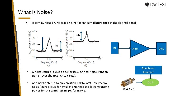
What is Noise? • In communication, noise is an error or random disturbance of the desired signal. 30 d. B 40 d. B 20 d. B • A noise source is used to generate electrical noise (random signals over the frequency range). • As a parameter in communication link budget, low receive noise figure allows for smaller antennas and lower transmit power for the same system performance. IN Out Amp Spectrum Analyzer DUT Noise Source
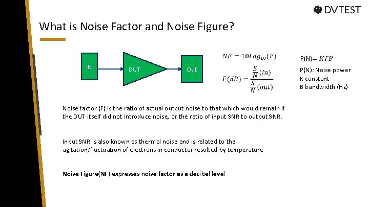
What is Noise Factor and Noise Figure? IN DUT Out Noise factor (F) is the ratio of actual output noise to that which would remain if the DUT itself did not introduce noise, or the ratio of input SNR to output SNR. Input SNR is also known as thermal noise and is related to the agitation/fluctuation of electrons in conductor resulted by temperature Noise Figure(NF) expresses noise factor as a decibel level P(N): Noise power K constant B bandwidth (Hz)
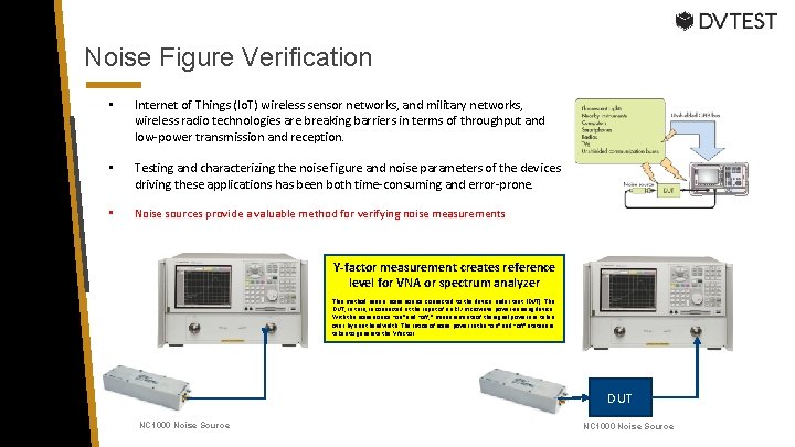
Noise Figure Verification • Internet of Things (Io. T) wireless sensor networks, and military networks, wireless radio technologies are breaking barriers in terms of throughput and low-power transmission and reception. • Testing and characterizing the noise figure and noise parameters of the devices driving these applications has been both time-consuming and error-prone. • Noise sources provide a valuable method for verifying noise measurements Y-factor measurement creates reference level for VNA or spectrum analyzer This method uses a noise source connected to the device under test (DUT). The DUT, in turn, is connected at the input of an RF/microwave power-sensing device. With the noise source “on” and “off, ” measurements of the signal power are taken over by a set bandwidth. The ratios of noise power in the “on” and “off” states are taken to generate the Y-factor. DUT NC 1000 Noise Source
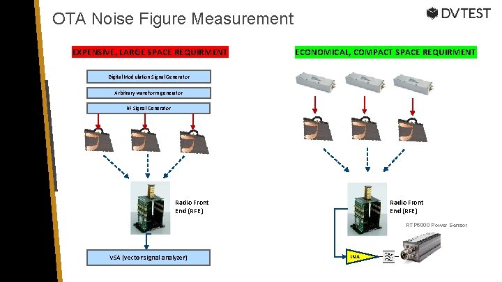
OTA Noise Figure Measurement EXPENSIVE, LARGE SPACE REQUIRMENT ECONOMICAL, COMPACT SPACE REQUIRMENT Digital Modulation Signal Generator Arbitrary waveform generator RF Signal Generator Radio Front End (RFE) RTP 5000 Power Sensor VSA (vector signal analyzer) LNA
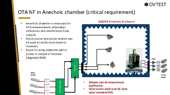
OTA NF in Anechoic chamber (critical requirement) • • db. SAFE Anechoic Enclosure Anechoic chamber is necessary for OTA measurement, eliminates reflections and interference from outside Noise source and power meters can be used to verify noise levels in receivers Noise for array elements add in power in output of receiver (degrades SNR) LNA p 1 p 2 PA box Rotation Power meter p 3 Noise source RF conditioning • • • Reduces cost of measurement significantly Noise source used to verify input noise instead of VSG

Over the Air (OTA) Path Loss using Noise • • • Over the air (OTA) is required by CTIA for testing of wireless devices. OTA measures parameters of signal over the air without physical connections to the device. Device manufacturers test Total Radiated Power (TRP) and Total isotropic sensitivity (TIS). Known gain antenna Calibrated noise sources can be used to create signals to verify path loss for RF enclosures in OTA testing Path Loss Verification for RF Chambers
Matthew B. Diessner Regional Sales Director Wireless Telecom Group

DVTEST and Wireless Telecom Group Power Meters and Noise Sources as Enclosure Accessories
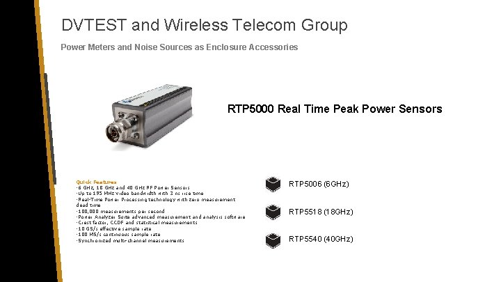
DVTEST and Wireless Telecom Group Power Meters and Noise Sources as Enclosure Accessories RTP 5000 Real Time Peak Power Sensors Quick Features • 6 GHz, 18 GHz and 40 GHz RF Power Sensors • Up to 195 MHz video bandwidth with 3 ns rise time • Real-Time Power Processing technology with zero measurement dead time • 100, 000 measurements per second • Power Analyzer Suite advanced measurement and analysis software • Crest factor, CCDF and statistical measurements • 10 GS/s effective sample rate • 100 MS/s continuous sample rate • Synchronized multi-channel measurements RTP 5006 (6 GHz) RTP 5518 (18 GHz) RTP 5540 (40 GHz)
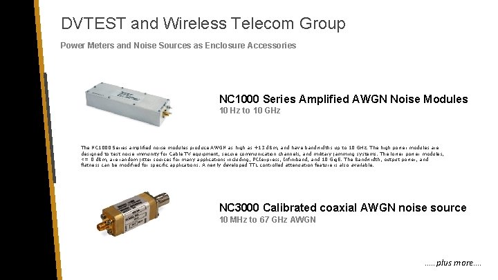
DVTEST and Wireless Telecom Group Power Meters and Noise Sources as Enclosure Accessories NC 1000 Series Amplified AWGN Noise Modules 10 Hz to 10 GHz The NC 1000 Series amplified noise modules produce AWGN as high as +13 d. Bm, and have bandwidths up to 10 GHz. The high power modules are designed to test noise immunity for Cable TV equipment, secure communication channels, and military jamming systems. The lower power modules, <= 0 d. Bm, are random jitter sources for many applications including, PCIexpress, Infiniband, and 10 Gig. E. The Bandwidth, output power, and flatness can be modified for specific applications. A newly developed TTL controlled attenuation feature is also available. NC 3000 Calibrated coaxial AWGN noise source 10 MHz to 67 GHz AWGN …. . plus more….

DVTEST and Wireless Telecom Group Potential Customers DEVICE MANUFACTURERS MIMO ARRAY CHIP PHASED ARRAY ANTENNA SERVICE PROVIDERS
DVTEST and Wireless Telecom Group Power Meters and Noise Sources as Enclosure Accessories • DVTEST offers the most comprehensive product line of RF enclosures on the market. • All customers performing an OTA measurement will require RF enclosures. • OTA “setups” require pathloss verification and characterization. • Noise sources and Power meters perform these verifications at a fraction of the cost of high frequency instruments. • Noise sources can also be used to calibrate noise ratio in spectrum analyzers, VNAs.
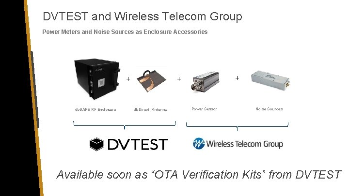
DVTEST and Wireless Telecom Group Power Meters and Noise Sources as Enclosure Accessories + db. SAFE RF Enclosure + + db. Direct Antenna Power Sensor Noise Sources Available soon as “OTA Verification Kits” from DVTEST
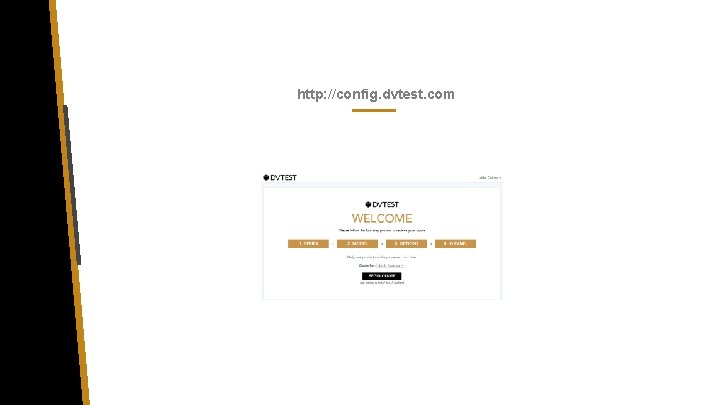
http: //config. dvtest. com

QUESTIONS AND ANSWERS

THANK YOU CONTACT US: sales@dvtest. com www. dvtest. com 2 -1795 Ironstone Manor, Pickering ON, Canada L 1 W 3 W 9

ADDITIONAL SLIDES
MIMO Arrays (LNA/PA Noise Level Verification)
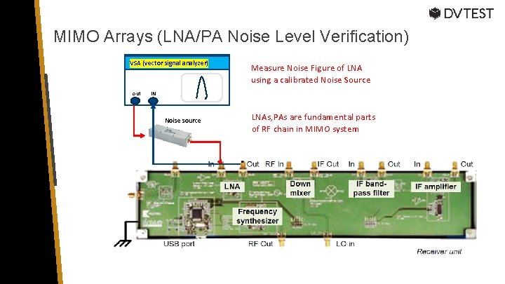
MIMO Arrays (LNA/PA Noise Level Verification) VSA (vector signal analyzer) out Measure Noise Figure of LNA using a calibrated Noise Source IN Noise source LNAs, PAs are fundamental parts of RF chain in MIMO system
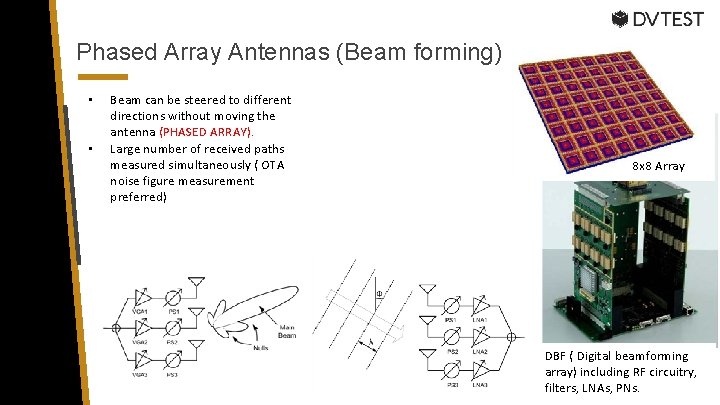
Phased Array Antennas (Beam forming) • • Beam can be steered to different directions without moving the antenna (PHASED ARRAY). Large number of received paths measured simultaneously ( OTA noise figure measurement preferred) 8 x 8 Array DBF ( Digital beamforming array) including RF circuitry, filters, LNAs, PNs.
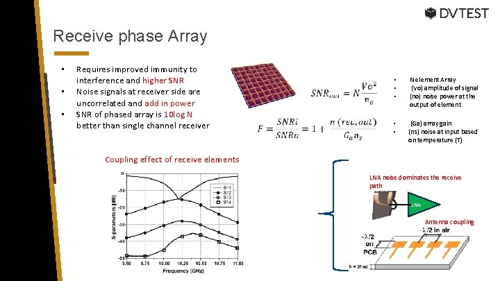
Receive phase Array • • • Requires improved immunity to interference and higher SNR Noise signals at receiver side are uncorrelated and add in power SNR of phased array is 10 log N better than single channel receiver • • • N element Array (Vo) amplitude of signal (no) noise power at the output of element • • (Ga) array gain (ns) noise at input based on temperature (T) Coupling effect of receive elements LNA noise dominates the receive path LNA Antenna coupling
- Slides: 22