Outstanding Nobel Prizes Laureates Hbomb Sakharov 1953 1975
 Lasers (Basov and Prokhorov, 1964) Superconductivity")
Outstanding Nobel Prizes Laureates H-bomb (Sakharov, 1953, 1975) Lasers (Basov and Prokhorov, 1964) Superconductivity (Ginzburg, 2003)

Vavilov Luminescence Department 1904 -1990 1891 -1951 1937 Cherenkov-Vavilov Effect 1958 Nobel price (with Tamm & Frank)

Evolution of Display Technologies OLEDs

Electronic display world market by technology

real OLED action

C. W. Tang Steven Van Slyke Organic Electroluminescent Diodes C. W. Tang, S. A. Van Slyke Appl. Phys. Lett. 51, 913 (1987)
 Aluminium tris(quinolin-8 -olate)")
Alq 3 (C 27 H 18 Al. N 3 O 3) Aluminium tris(quinolin-8 -olate)

Example of flexible OLED

Transparent OLED for notebook

Transparent cell phone

Transparent OLED for Lighting

Advantages: • • Robust Design - OLED’s are tough enough to use in portable devices such as cellular phones, digital video cameras, DVD players, car audio equipment and PDA’s. Viewing Angles – Can be viewed up to 160 degrees, OLED screens provide a clear and distinct image, even in bright light. High Resolution – High information applications including videos and graphics, active-matrix OLED provides the solution. Each pixel can be turned on or off independently to create multiple colors in a fluid and smooth edged display. “Electronic Paper” – OLED’s are paper-thin. Due to the exclusion of certain hardware goods that normal LCD’s require, OLED’s are as thin as a dime. Production Advantages – Up to 20% to 50% cheaper than LCD processes. Plastics will make the OLED tougher and more rugged. The future quite possibly could consist of these OLED’s being produced like newspapers, rather than computer “chips”. Video Capabilities – They hold the ability to handle streamlined video, which could revolutionize the PDA and cellular phone market. Hardware Content – Lighter and faster than LCD’s. Can be produced out of plastic and is bendable. Also, OLED’s do not need lamps, polarizers, or diffusers. Power Usage – Takes less power to run (2 to 10 volts).

Disadvantages: • Sunlight Readability – OLED’s emit light. Bright sunlight interferes and washes out the image. • MTBF vs. Color – The reliability of OLEDs have been dramatically improved. But the colors still degrade at a different rate. MTBF = 150, 000 hours for red, 80, 000 hours for green & blue. • Overcoming LCD’s – LCD’s have predominately been the preferred form of display for the last few decades. LCD manufacturers will continue to improve their products and search for ways to reduce production costs.

Which way? QD-OLED Light Emitting Organic Transistor Roll-to-Roll

Flexible OLED

Roll-to-Roll technology

2 May 2010 EQE = 5%
.")
The first idea of QD-OLED Coe et al. , Nature 420, 800 (2002).
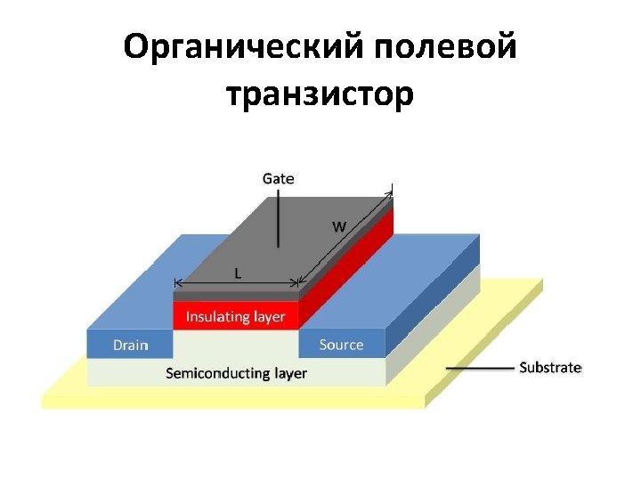

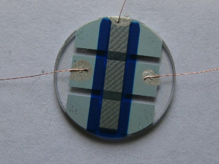
FIAN OFET
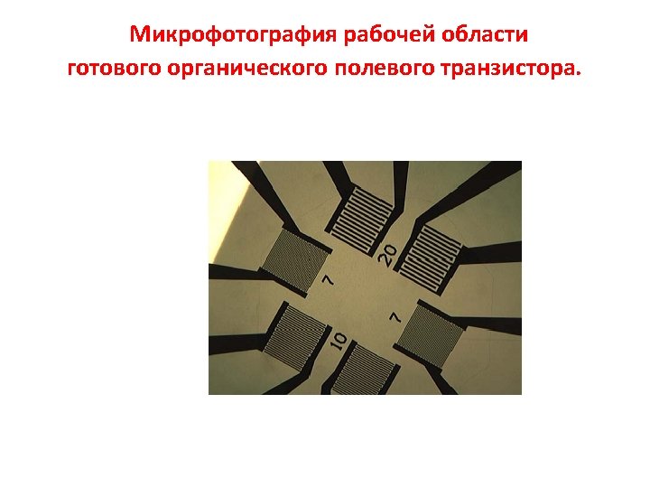

3 Ion/Ioff ~ 10

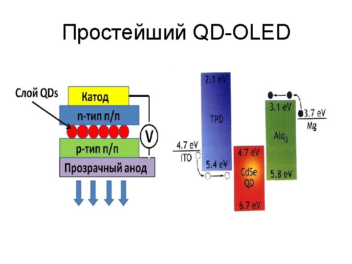
Hybrid OLED Cathode Anode

Energy level structure

QDs

Synthesis of Colloidal Quantum Dots

Synthesis of Colloidal Quantum Dots

QDs Layer Formation TPD/QD solution in chloroform

QDs Layer Formation TPD/QDs in solution chloroform
, 2005")
QD - OLED FIAN suggestion for ITRI (Taiwan), 2005

FIAN vacuum deposition set-up OLED-FIAN-1

FIAN spin-coating set-up OLED-FIAN -2
")
Working OLED sample (June, 2010)
")
Working OLED sample (June, 2010)

Semiconductor QDs Size change

Cd. Se example

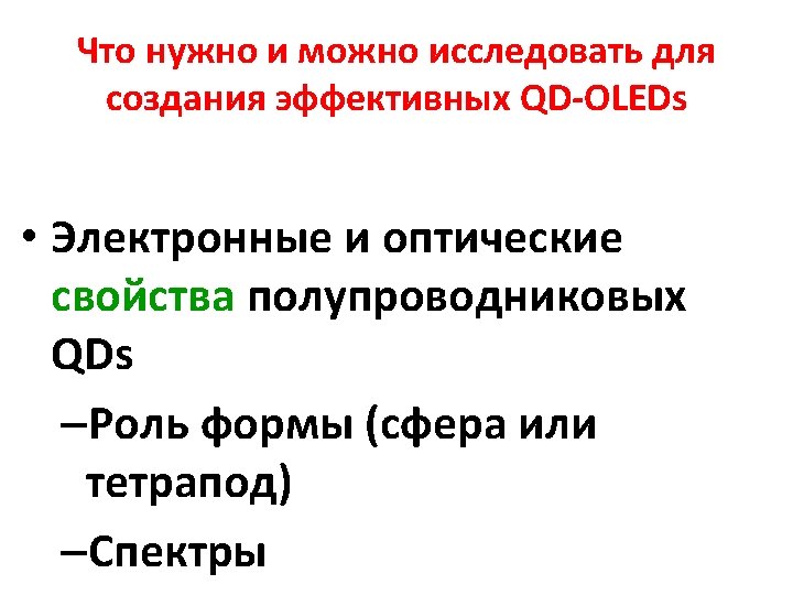
Quantum Dots Shape • Spherical form • Tetrapoid form

Anisotropic QDs
")
Quantum Dots from Dr. R. Vasiliev Group (MSU)

Nanotetrapod Model Cd. Te/Cd. Se nanotetrapod ТЕМ image Nanoterapod construction
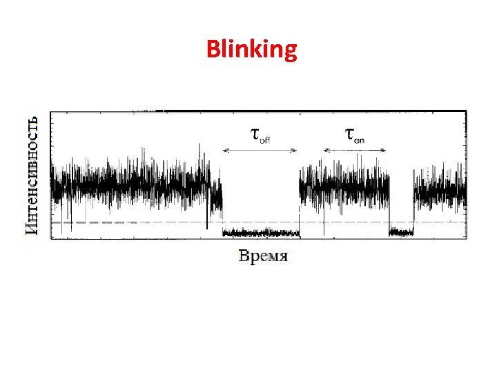

Blinking role

e hv emission “On” state QD trap

“Off” state e hv No emission QD trap
")
Time-of-Flight Set-up (excitation 266 нм)

COMMON CONCLUSION • Towards to QD-OLEDs • QDs processes are shorter than 1 ms. We need a new method for blinking study (role shell thickness). • No exponential kinetics of Cd. Te/Cd. Se QDs related with space charge separation • Hole mobility is independent from QDs concentration in QDs doped organic matrix. The energetic disorder σ is increased for concentrations of QDs (92 10 мe. V up 127 5 мe. V). • Additional studies of QDs doped organic matrix are needed.
- Slides: 64