
Output Concepts Start with some basics display devices
Output Concepts
Start with some basics: display devices Just how do we get images onto a screen? n Most prevalent device: CRT n – Cathode Ray Tube – AKA TV tube 2
Cathode Ray Tubes n Cutting edge 1930’s technology – (basic device actually 100 yrs old) – Vacuum tube (big, power hog, …) – Refined some, but no fundamental changes n But still dominant – Because TVs are consumer item – LCD’s just starting to challenge 3
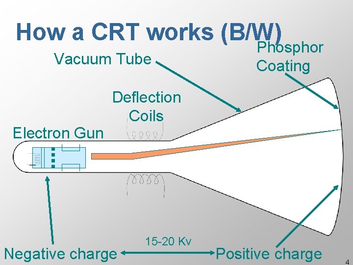
How a CRT works (B/W) Vacuum Tube Electron Gun Phosphor Coating Deflection Coils Negative charge 15 -20 Kv Positive charge 4
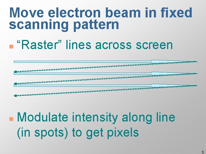
Move electron beam in fixed scanning pattern n n “Raster” lines across screen Modulate intensity along line (in spots) to get pixels 5
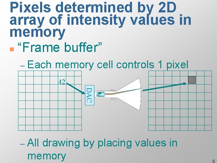
Pixels determined by 2 D array of intensity values in memory n “Frame buffer” – Each memory cell controls 1 pixel 42 DAC – All drawing by placing values in memory 6
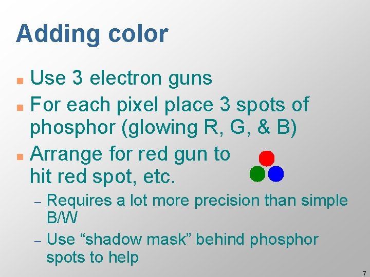
Adding color Use 3 electron guns n For each pixel place 3 spots of phosphor (glowing R, G, & B) n Arrange for red gun to hit red spot, etc. n Requires a lot more precision than simple B/W – Use “shadow mask” behind phosphor spots to help – 7
Color frame buffer n Frame buffer now has 3 values for each pixel – each value drives one electron gun – can only see ~ 2^8 gradations of intensity for each of R, G, &B – 1 byte ea => 24 bits/pixel => full color 8
Other display technologies: LCD Liquid Crystal Display n Uses material with unusual physical properties: liquid crystal n – rest state: rotates polarized light 90° – voltage applied: passes as is 9
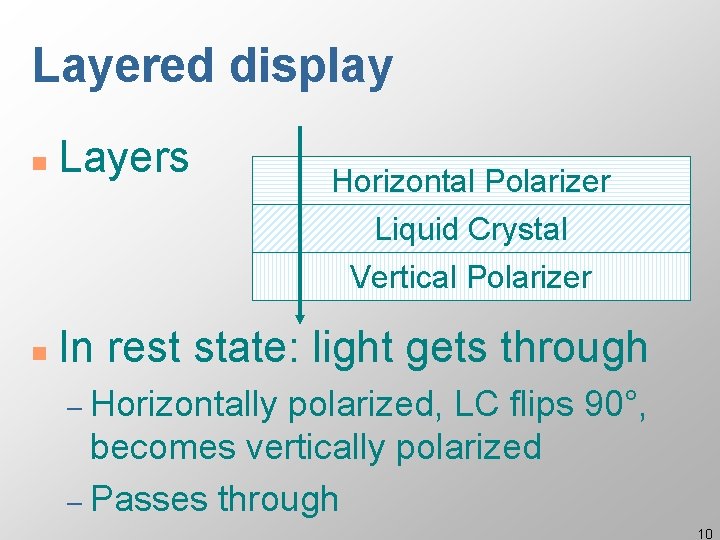
Layered display n Layers n In rest state: light gets through Horizontal Polarizer Liquid Crystal Vertical Polarizer – Horizontally polarized, LC flips 90°, becomes vertically polarized – Passes through 10
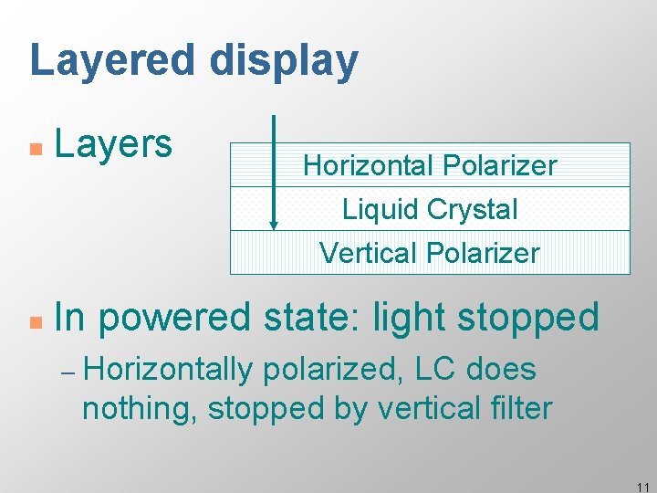
Layered display n Layers n In powered state: light stopped Horizontal Polarizer Liquid Crystal Vertical Polarizer – Horizontally polarized, LC does nothing, stopped by vertical filter 11
Lots of other interesting/cool technologies n Direct retinal displays – University n of Washington HIT lab Set of 3 color lasers scan image directly onto retinal surface – Scary but it works – Very high contrast, all in focus – Potential for very high resolution – Has to be head mounted 12
All these systems use a frame buffer n Again, each pixel has 3 values – Red, n Green Blue Why R, G, B? – R, G, and B are particular freq of light – Actual light is a mix of lots of frequencies – Why is just these 3 enough? 13
Why R, G, & B are enough n Eye has receptors (cones) that are sensitive to (one of) these – Eye naturally quantizes/samples frequency distribution n 8 -bit of each does a pretty good job, but… some complications 14
Complications – Eye’s perception is not linear (logarithmic) – CRT’s (etc. ) do not respond linearly – Different displays have different responses Fdifferent dynamic ranges Fdifferent color between devices! – Need to compensate for all of this 15
Gamma correction Response of all parts understood (or just measured) n Correct: uniform perceived color n – Normally table driven F 0… 255 in (linear intensity scale) F 0…N out to drive guns • N=1024 or 2048 typical 16
Unfortunately, gamma correction not always done n E. g. , TV is not gamma corrected èKnowing RGB values does not tell you what color you will get! n For systems you control: do gamma correction 17
24 bits/pixel => full color, but what if we have less? n 16 bits/pixel – 5 each in RGB with 1 left over – decent range (32 gradations each) n Unfortunately often only get 8 – 3 bits for GB, 2 for R – not enough – Use a “trick” instead 18
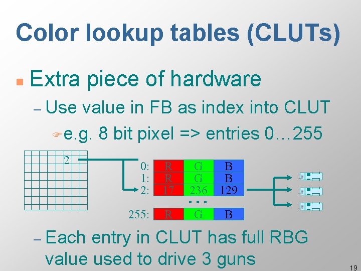
Color lookup tables (CLUTs) n Extra piece of hardware – Use value in FB as index into CLUT Fe. g. 8 bit pixel => entries 0… 255 2 0: 1: 2: R R 17 255: R G G 236 B B 129 G B . . . – Each entry in CLUT has full RBG value used to drive 3 guns 19
Palettes n 8 bits / pixel with CLUT – Gives “palette” of 256 different colors – Chosen from 16 M – Can do a lot better than uniform by picking a good palette for the image to be displayed (nice algorithms for doing this) 20
Software models of output (Imaging models) Start out by abstracting the HW n Earliest imaging models abstracted early hardware: vector refresh n – stroke or vector (line only) models 21
Vector models n Advantages – can freely apply mathematical xforms FScale rotate, translate FOnly have to manipulate endpoints n Disadvantages – limited / low fidelity images Fwireframe, no solids, no shading 22
Current dominant: Raster models n Most systems provide model pretty close to raster display HW – integer coordinate system – 0, 0 typically at top-left with Y down – all drawing primitives done by filling in pixel color values (values in FB) 23
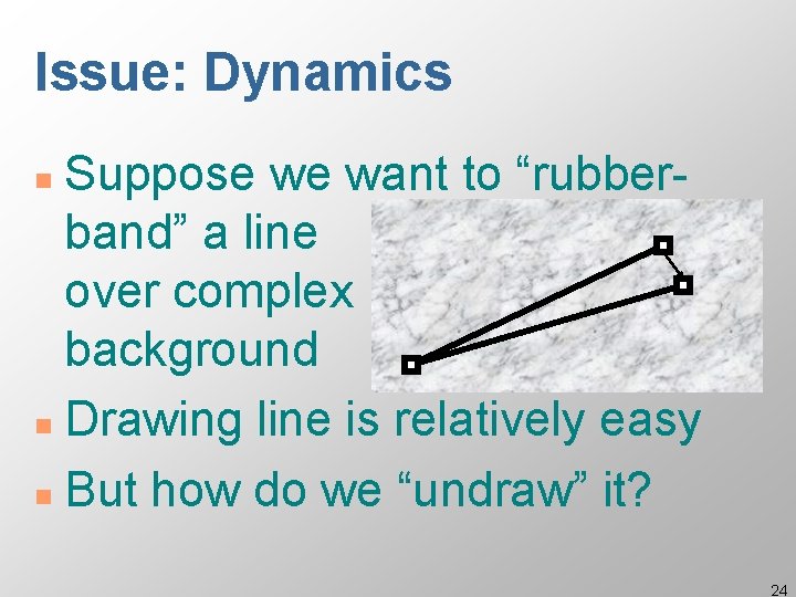
Issue: Dynamics Suppose we want to “rubberband” a line over complex background n Drawing line is relatively easy n But how do we “undraw” it? n 24
Undrawing things in raster model n Ideas? (red, su, xo, pal, fwd) 25
Undrawing things in raster models Four solutions: n 1) Redraw method n FRedraw all the stuff under FThen redraw the line Relatively expensive (but HW is fast) FNote: don’t have to redraw all, just “damaged” area – Simplest and most robust (back) – 26
How to undraw n 2) “Save-unders” – When you draw the line, remember what pixel values were “under” it – To undraw, put back old values – Issue: (what is it? ) 27
How to undraw n 2) “Save-unders” – When you draw the line, remember what pixel values were “under” it – To undraw, put back old values – Issue: what if “background” changes n Tends to either be complex or not robust (back) – Typically used only in special cases 28
How to undraw n 3) Use bit manipulation of colors – Colors stored as bits – Instead of replacing bits XOR with what is already there FA ^ B == ? 29
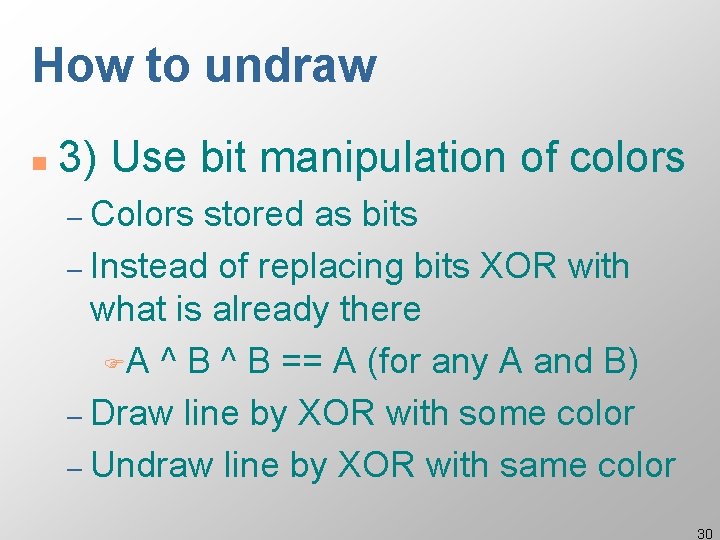
How to undraw n 3) Use bit manipulation of colors – Colors stored as bits – Instead of replacing bits XOR with what is already there FA ^ B == A (for any A and B) – Draw line by XOR with some color – Undraw line by XOR with same color 30
Issue with XOR? n What is it? 31
Issue with XOR n Colors unpredictable – Some. Color ^ Blue == ? ? FDon’t know what color you will get FNot assured of good contrast • Ways to pick 2 nd color to maximize contrast, but still get “wild” colors 32
Undraw with XOR n Advantage of XOR undraw – Fast – Don’t have to worry about what is “under” the drawing, just draw n In the past used a lot where dynamics needed – May not be justified on current HW (back) 33
How to undraw n 4) Simulate independent bitplanes using CLUT “tricks” – Won’t consider details, but can use tricks with CLUT to simulate set of transparent layers – Probably don’t want to use this solution, but sometimes used for special cases like cursors (back) 34
Higher level imaging models n Simple pixel/raster model is somewhat impoverished – Integer coordinate system – No rotation (or good scaling) – Not very device independent 35
Higher level imaging models n Would like: – Real valued coordinate system Foriented as Descarte intended? – Support for full transformations Freal scale and rotate – Richer primitives Fcurves 36
Stencil and paint model n All drawing modeled as placing paint on a surface through a “stencil” – Stencil modeled as closed curves (e. g. , splines) n Issue: how do we draw lines? 37
Stencil and paint model n All drawing modeled as placing paint on a surface through a “stencil” – Modeled n as closed curves (splines) Issue: how do we draw lines? – (Conceptually) very thin stencil along direction of line – Actually special case & use line alg. 38
Stencil and paint model n Original model used only opaque paint – Modeled hardcopy devices this was developed for (at Xerox PARC) n Current systems now support “paint” that combines with “paint” already under it – e. g. , translucent paint (“alpha” values) 39
Stencil and paint model(s) n Postscript model is based on this approach – Dominant model for hardcopy, but not screen n New Java drawing model (Java 2 D) also takes this approach 40
Stencil and paint model(s) n Advantages – Resolution & device independent Fdoes best job possible on avail HW FDon’t need to know size of pixels – Can support full transformations Frotate & scale 41
Stencil and paint model(s) n Disadvantages – Slower FLess and less of an issue FBut interactive response tends to be dominated by redraw time – Much harder to implement 42
Stencil and paint model(s) n Stencil and paint type models generally the way to go – But have been slow to catch on FMarket forces tend to keep us with old models FMuch harder to implement – But starting to see these models for screen based stuff (esp. w/ Java 2 D) 43
Object-oriented abstractions for drawing n Most modern systems provide uniform access to all graphical output capabilities / devices – Treated as abstract drawing surface F“Canvas” abstraction Fsub. Arctic: drawable FMacintosh: graf. Port FWindows: device context 44
Object-oriented abstractions for drawing n Abstraction provides set of drawing primitives – Might be drawing on… FWindow, direct to screen, inmemory bitmap, printer, … – Key point is that you can write code that doesn’t have to know which one 45
Object-oriented abstractions for drawing n Generally don’t want to depend on details of device but sometimes need some: – How big is it – Is it resizable – Color depth (e. g. , B/W vs. full color) – Pixel resolution (for fine details only) 46
A particular drawing abstraction: sub_arctic. output. drawable n Subclass of java. awt. Graphics – Most of model taken directly from AWT (warts and all) – Only way to draw on the screen in Java (Graphics 2 D came out only recently) FGood that there is an abstraction FCould be a bit better in a few places 47
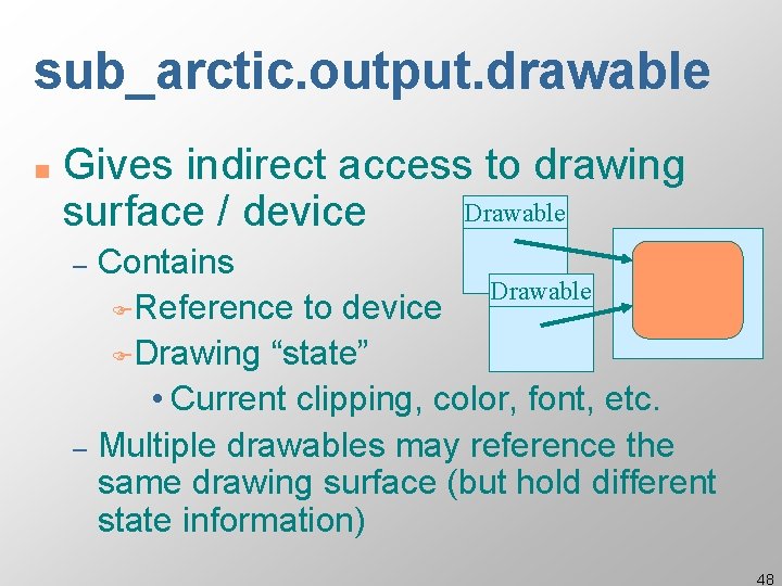
sub_arctic. output. drawable n Gives indirect access to drawing Drawable surface / device Contains Drawable FReference to device FDrawing “state” • Current clipping, color, font, etc. – Multiple drawables may reference the same drawing surface (but hold different state information) – 48
Handout on drawable. . . 49
Fonts and drawing strings n Font provides description of the shape of a collection of chars – Shapes are called glyphs Plus information e. g. about how to advance after drawing a glyph n And aggregate info for the whole collection n 50
Fonts n Typically specified by: A family or typeface Fe. g. , courier, helvetica, times roman – A size (normally in “points”) – A style Fe. g. , plain, italic, bold & italic Fother possibles (from mac): underline, outline, shadow – 51
Points n An odd and archaic unit of measurement – 72. 27 points per inch FOrigin: 72 per French inch (!) – Postscript rounded to 72/inch most have followed – Early Macintosh: point==pixel (1/75 th) 52
Font. Metrics n Objects that allow you to measure characters, strings, and properties of whole fonts 53
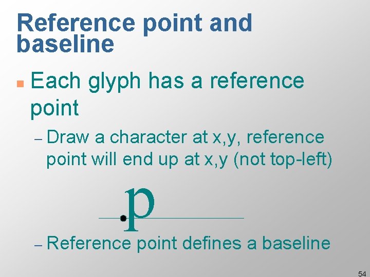
Reference point and baseline n Each glyph has a reference point – Draw a character at x, y, reference point will end up at x, y (not top-left) p – Reference point defines a baseline 54
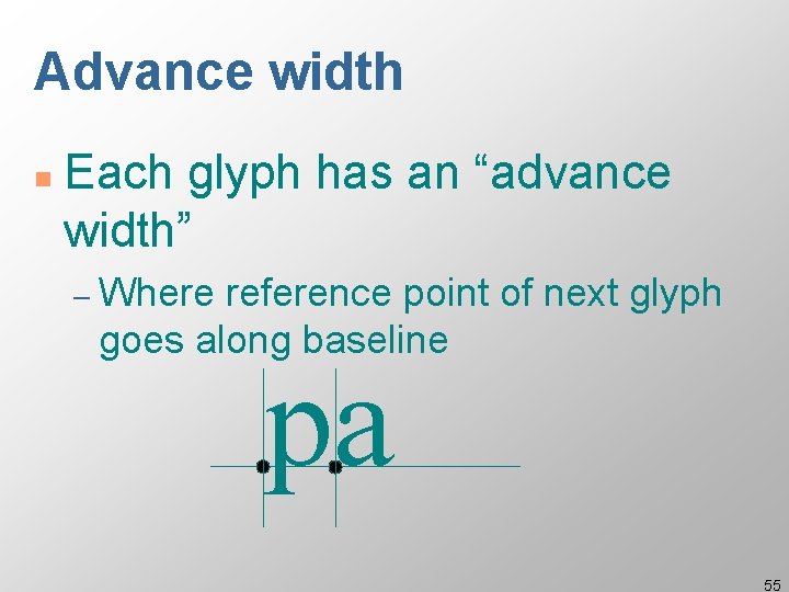
Advance width n Each glyph has an “advance width” – Where reference point of next glyph goes along baseline pa 55
Widths n Each character also has a bounding box width – May be different from advance width in some cases – Don’t get this with AWT Font. Metrics, so there “width” means “advance width” 56

Ascent and decent n Glyphs are drawn both above and below baseline – Distance below: “decent” of glyph – Distance above: “ascent” of glyph Decent p Ascent 57
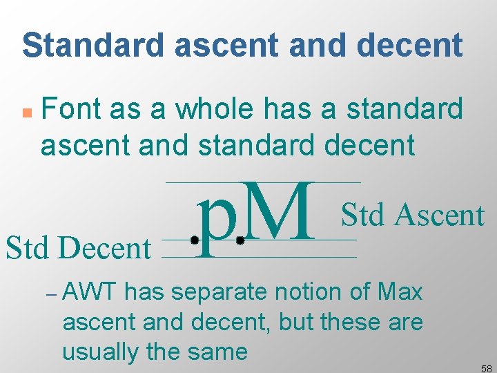
Standard ascent and decent n Font as a whole has a standard ascent and standard decent Std Decent p. M Std Ascent – AWT has separate notion of Max ascent and decent, but these are usually the same 58
Leading n Leading = space between lines of text – Pronounce “led”-ing after the lead strips that used to provide it – space between bottom of standard decent and top of standard ascent Fi. e. interline spacing 59
Height n Height of character or font – ascent + decent + leading – not standard across systems: on some systems doesn’t include leading (but does in AWT) 60
Font. Metrics n Font. Metrics objects give you all of above measurements – for chars & Strings – also char and byte arrays – for whole fonts n Drawable method will get you Font. Metrics for a given font 61

62
- Slides: 62