Outline Motivation LTEA and Carrier Aggregation Component Carriers

 is used in LTE-Advanced in order to increase the")


 is introduced in R 10 –With")

 and Secondary Component Carriers (SCCs) • When carrier aggregation")


 • Serving cells with the")
 • The LTE-Advanced UE can be allocated DL and")


 Max Number of")


: Two Main Alternatives • Either resources are scheduled on the same")


HSDPA is the natural evolution of HSPA by")


- Slides: 42
Outline • Motivation • LTE-A and Carrier Aggregation • Component Carriers: PCC and SCC • Aggregation Alternatives • CA Issues • CA in Actions 2
Motivation • Carrier Aggregation (CA) is used in LTE-Advanced in order to increase the bandwidth, and thereby increase the bitrate –The aggregation is based on R 8/R 9 carriers to keep backward compatibility with R 8 and R 9 Ues –Carrier aggregation can be used for both FDD and TDD 3
Toward Gigabit LTE 4
CA Examples • Carrier aggregation lets mobile operators bond together disparate spectrum bands to add capacity and provide faster data rates in their networks • Examples – Downlink speeds of up to 225 Mbps have been achieved by aggregating 20 MHz and 10 MHz carriers in the 800 MHz and 1800 MHz bands – 300 Mbps has been delivered by combining two 20 MHz carriers in 1800 MHz and 2. 6 GHz bands – One trial has combined one 20 MHz block in the 1800 MHz band with two 20 MHz carriers in the 2. 6 GHz band to demonstrate peak speeds of 450 Mbps 5
The Road to CA • Carrier Aggregation (CA) is introduced in R 10 –With backward compatibility to R 8 –to increase the total bandwidth available to UEs and hence their maximum bitrates • When CA is used –A number of R 8 carriers, referred to as Component Carriers (CC), are aggregated –Any CA-capable UE can be allocated resources on all CCs, • while R 8/R 9 UEs can only be allocated resources on one CC. 6
Component Carrier • Each aggregated carrier is referred to as a component carrier, CC – The component carrier can have a bandwidth of 1. 4, 3, 5, 10, 15 or 20 MHz and – A maximum of five component carriers can be aggregated • hence the maximum aggregated bandwidth is 100 MHz • In FDD the number of aggregated carriers can be different in DL and UL – However, the number of UL component carriers is always equal to or lower than the number of DL component carriers – The individual component carriers can also be of different bandwidths • For TDD the number of CCs as well as the bandwidths of each CC will normally be the same for DL and UL 7
The Primary Component Carrier (PCC) and Secondary Component Carriers (SCCs) • When carrier aggregation is used there a number of serving cells, one for each component carrier – Different component carriers can be planned to provide different coverage, i. e. different cell size • The RRC connection is only handled by one cell, the Primary serving cell, served by the Primary Component Carrier (DL and UL PCC) – It is also on the DL PCC that the UE receives NAS information, such as security parameters. – In idle mode the UE listens to system information on the DL PCC – On the UL PCC PUCCH is sent • The other component carriers are all referred to as Secondary Component Carriers (DL and UL SCC), serving the Secondary serving cells – The SCCs are added and removed as required, while the PCC is only changed at handover • The coverage of the serving cells may differ, for example due to that CCs on different frequency bands will experience different path loss – In the case of inter-band carrier aggregation the component carriers will experience different path loss, which increases with increasing frequency – Note that for UEs using the same set of CCs, can have different PCC 8
Primary and Secondary Serving Cells • Each component carrier corresponds to a serving cell – The different serving cells may have different coverage • Carrier aggregation on three component carriers are used for the black UE – The white UE is not within the coverage area of the red component carrier 9
Radio Interface to Support Carrier Aggregation 10
Support Serving Cells with Different Timing Advance (TA) • Serving cells with the same TA belongs to the same TA Group (TAG) • From R 11 it will be possible to handle CA with CCs requiring different timing advance (TA), for example combining CC from e. NB with CC from RRH – For heterogeneous network planning the use of for example remote radio heads (RRH) is of importance 11
Example of Carrier Aggregation (FDD) • The LTE-Advanced UE can be allocated DL and UL resources on the aggregated resource consisting of two or more Component Carriers (CC) – The R 8/R 9 UEs can be allocated resources on any ONE of the CCs – The CCs can be of different bandwidths 12
Scenario of UE with CA 13
Definition of CA Aggregated Channel Bandwidth Intra-band contiguous Intra-band noncontiguous Inter-band 14
Intra-band Inter-band Aggregation Alternatives • The spacing between the centre frequencies of two contiguous CCs is Nx 300 k. Hz, N=integer • For non-contiguous cases the CCs are separated by one, or more, frequency gap(s) 15
Three Band Allocation for Aggregations • Intra-band contiguous allocation –The easiest way to arrange aggregation would be to use contiguous component carriers within the same operating frequency band (as defined for LTE) –This might not always be possible, due to operator frequency allocation scenarios. • Intra-band non-contiguous allocation –The component carriers belong to the same operating frequency band, but have a gap, or gaps, in between • Inter-band non-contiguous allocation –The component carriers belong to different operating frequency bands 16
Definitions and Notations for CA • CA is initially specified for only a few combinations of E-UTRA operating bands and number of CCs • New definitions to specify different CA combinations – Aggregated Transmission Bandwidth Configuration (ATBC): total number of aggregated physical resource blocks (PRB) – CA Bandwidth Class: indicates a combination of maximum ATBC and maximum number of CCs. In R 10 and R 11 three classes are defined • Class A: ATBC ≤ 100, maximum number of CC = 1 • Class B: ATBC ≤ 100, maximum number of CC = 2 • Class C: 100 < ATBC ≤ 200, maximum number of CC = 2 – CA Configuration: indicates a combination of E-UTRA operating band(s) and CA bandwidth class(es), to exemplify the configuration • CA_1 C indicates intra-band contiguous CA on E-UTRA operating band 1 and CA bandwidth class C • CA_1 A_1 A, indicates intra-band non-contiguous CA on band 1 with a one CC on each side of the intra-band gap • CA_1 A_5 B indicates inter-band CA, on operating band 1 with bandwidth class A and operating band 5 with bandwidth class B 17
3 GPP Releases for CA • The increase in bandwidth in LTE-Advanced is provided through aggregation of R 8/R 9 carriers – Keep backward compatibility with R 8 and R 9 mobiles – Carrier aggregation can be used for both FDD and TDD • In R 10 there are – Two component carriers in the DL and – Only one in the UL (hence no carrier aggregation in the UL) • In R 11 there are – Two component carriers DL and – One or two component carriers in the UL when carrier aggregation is used 18
CA Development of 3 GPP Releases • 3 GPP Beyond Release 10 Release 11 Release 12 DL intra-Band Contiguous • DL inter_Band • Maximum 2 DL Carrier Aggregation • DL intra-Band non Contiguous 3 DL CA 2 UL CA (inter Band & inter Band non contiguous) • FDD+TDD • Dual Connectivity • • LAA (Licensed. Assisted Access) 4 DL CA 19
Changes to R 8/R 9 for Carrier Aggregation • Introduction of carrier aggregation influences mainly MAC and the physical layer protocol, but also some new RRC messages are introduced • In order to keep R 8/R 9 compatibility the protocol changes will be kept to a minimum – Basically each component carrier is treated as an R 8 carrier – Some changes are required, such as • new RRC messages in order to handle SCC • MAC must be able to handle scheduling on a number of CCs – Major changes on the physical layer are for example that –Signaling information about scheduling on CCs must be provided DL as well as HARQ ACK/NACK per CC must be delivered UL and DL 20
Three CA Configurations Defined for R 10 Maximum Aggregated Bandwidth (MHz) Max Number of CC CA_1 C 40 2 CA_40 C 40 2 CA_1 A_5 A 20 1 + 1 Type of CA CA and Configuration Duplex Type Intra-band contiguous FDD Intra-band contiguous TDD Inter-band FDD 21
CA Configurations Defined for R 11 and Beyond • In R 11 a large number of additional CA configurations are defined – The maximum aggregated bandwidth is still 40 MHz and maximum number of CC is 2 – For both R 10 and R 11 any UL CC will have the same bandwidth as the corresponding DL CC – Also for inter-band CA there will only be ONE UL CC, i. e. no UL CA • Check updated table in the “Carrier Aggregation for LTE” document for each release Type of CA and Duplex Type CA Configuration Maximum Aggregated Bandwidth (MHz) Max Number of CC Intra-band contiguous FDD CA_1 C 40 2 CA_7 C 40 2 Intra-band contiguous TDD CA_38 C 40 2 CA_40 C 40 2 CA_41 C 40 2 CA_1 A_5 A 20 1 + 1 CA_11 A_18 A 25 1 + 1 CA_3 A_5 A 30 1 + 1 CA_1 A_18 A 35 1 + 1 CA_3 A_7 A 40 1 + 1 CA_25 A 20 1 + 1 Inter-band FDD Intra-band non-ontiguous FDD 22
Examples of CA Combinations 23
CA with Cross-Carrier Scheduling • Cross-carrier scheduling is an important feature in heterogeneous networks • Map the Physical DL control channels (PDCCH) on different CCs in the large and small cells – The PDCCH, carrying DL Control Information (DCI) with scheduling information, must be received by the UEs at the cell edge – PDCCH may be transmitted with higher power than the traffic channels – Hence, using different carriers for the PDCCH in the large and small cells reduces the risk of PDCCH interference 24
Example of CA with Cross-Carrier Scheduling 25
CA Scheduling (FDD): Two Main Alternatives • Either resources are scheduled on the same carrier as the grant is received, or so called cross-carrier scheduling may be used 26
CA with Joint Traffic Scheduling 27
Combining CCs from e. NBs with CCs from RRHs • From LTE R 11 onwards it is possible to handle CA with CCs requiring different timing advance (TA) 28
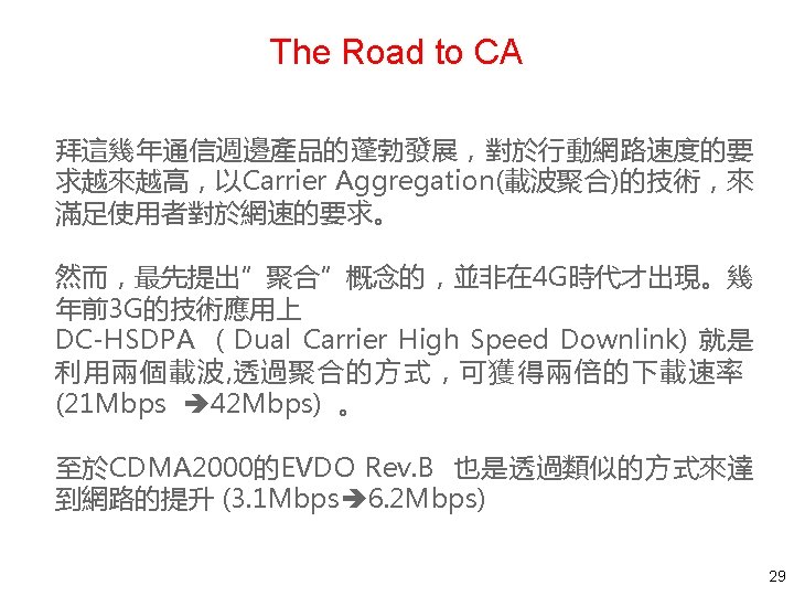
CA and DC-HSDPA • Dual Cell (DC-)HSDPA is the natural evolution of HSPA by means of carrier aggregation in the downlink - UMTS licenses are often issued as 10 or 15 MHz paired spectrum allocations - The basic idea of the multicarrier feature is to achieve better resource utilization and spectrum efficiency by means of joint resource allocation and load balancing across the downlink carriers • An advanced HSPA network can theoretically support up to 28 Mbit/s and 42 Mbit/s with a single 5 MHz carrier for Rel 7 (MIMO with 16 QAM) and Rel 8 (64 -QAM + MIMO), in good channel condition with low correlation between transmit antennas • An alternative method to double the data rates is to double the bandwidth, i. e. 10 MHz by using DC-HSDPA - New HSDPA UE categories 21 -24 have been introduced that support DCHSDPA - DC-HSDPA can support up to 42 Mbit/s and it does not need to rely on MIMO transmission 32
CA Issues – Channel Spacing 33
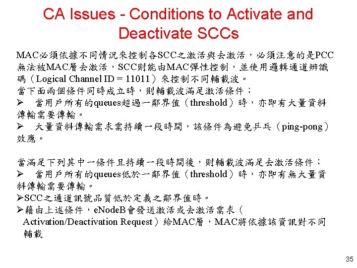
CA Issues – Transmitter Characteristics 34
Steps of Adding a Second Carrier 36
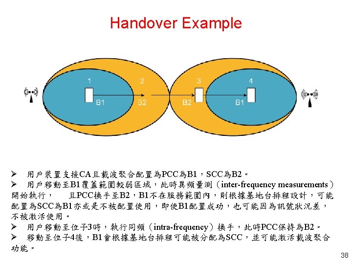
CA Issues - Handover 37
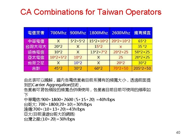
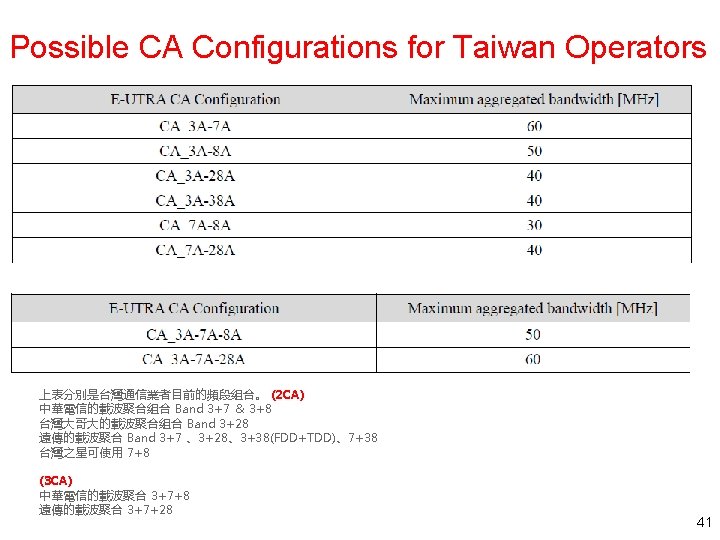
Band Allocations of Taiwan Operators 39
Summary • CA lets mobile operators bond together disparate spectrum bands to add capacity and provide faster data rates in their networks • Technical fundaments – Component Carriers: PCC and SCC – Aggregation combinations • CA Issues for deployments 42