Outline Introduction to LWA LWA Architecture LWAAP E

 (TS 36. 300/22 A) • E UTRAN supports LWA operation whereby")

 The Xw U interface is used to deliver")
 • e. NB WT control plane signaling for")


 on the Xw Interface • • • Interface to physical")


 • Xw SETUP")
 – candidate")


 •")
 –")


 – E-RAB")


")


")


- Slides: 67
Outline • Introduction to LWA • LWA Architecture • LWAAP • E UTRAN and Wireless LAN (WLAN) – Xw in Layer 1 – Signaling Transport – Xw Application Protocol (Xw. AP) – Xw Data Transport – Xw Interface User Plane Protocol
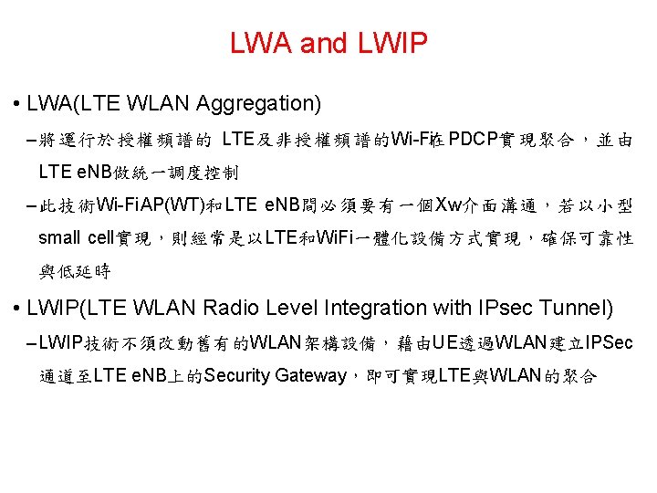
LTE-WLAN Aggregation (LWA) (TS 36. 300/22 A) • E UTRAN supports LWA operation whereby a UE in RRC_CONNECTED is configured by the e. NB to utilize radio resources of LTE and WLAN – WLAN AP/AC only interacts with e. NB; no interaction with the Core Network – LWA is controlled by e. NB, based on UE measurement reporting – When LWA is activated, e. NB configures one or more bearers as LWA bearers • Two scenarios are supported depending on the backhaul connection between LTE and WLAN – Collocated LWA scenario for an ideal/internal backhaul – Non collocated LWA scenario for a non ideal backhaul • WLAN Termination (WT) terminates the Xw interface for WLAN C Plane connectivity of e. NB and WT for LWA U Plane connectivity of e. NB and WT for LWA 3
LWA Radio Protocol Architecture • In LWA, the radio protocol architecture that a particular bearer uses depends on the LWA backhaul scenario and how the bearer is set up • Two bearer types exist for LWA: split LWA bearer and switched LWA bearer LWA Radio Protocol Architecture for the Collocated Scenario • LWA allows a single bearer to be configured to utilize LTE and WLAN simultaneously • Split and switched bearers are supported • R 13 LWA supports aggregation in downlink only, while uplink transmission is always on LTE • Packets (PDCP PDUs) belonging to LWA bearer can be sent by e. NB via LTE or WLAN simultaneously • LWA uses Ether. Type 0 x 9 E 65 allocated by IEEE RAC LWA Radio Protocol Architecture for the Non Collocated Scenario 4
LWA : User Plane (Non collocated) The Xw U interface is used to deliver LWAAP PDUs between e. NB and WT
LWA : Control Plane (Non collocated) • e. NB WT control plane signaling for LWA is performed by means of Xw C interface signaling
LWA : Mobility • A WLAN mobility set is a set of one or more WLAN Access Points (APs) – identified by one or more BSSID/HESSID/SSIDs, • within which WLAN mobility mechanisms apply while the UE is configured with LWA bearer(s) • i. e. , the UE may perform mobility between WLAN APs belonging to the mobility set without informing the e. NB
LWA : Operation • WT Addition • WT Modification • WT Release
Abbreviations & Definitions l. E UTRAN : Evolved Universal Terrestrial Radio Access Network l. O&M : Operations & Maintenance l. Xw : logical interface between e. NB and WT l. WT : WLAN Termination l. IANA : Internet Assigned Numbers Authority l. IETF : Internet Engineering Task Force l. PPP : Point to Point Protocol l. RFC : Request for Comments l. SCTP : Stream Control Transmission Protocol l. Elementary Procedure: a unit of interaction between an e. NB and WT, consists of an initiating message and possibly a response message – Class 1: Elementary Procedures with response (success or failure), – Class 2: Elementary Procedures without response l. E RAB : E UTRAN Radio Access Bearer. An E RAB uniquely identifies the concatenation of an S 1 Bearer and the corresponding Data Radio Bearer. When an E RAB exists, there is a one to one mapping between this E RAB and an EPS bearer of the Non Access Stratum
Definitions and Terms l. LWA bearer : in LTE WLAN Aggregation, a bearer whose radio protocols are located in both the e. NB and the WLAN to use both e. NB and WLAN resources l. WLAN Termination : the logical node that terminates the Xw interface on the WLAN side. l. PDCP : Packet Data Convergence Protocol l. RCLWI : RAN Controlled LTE WLAN Interworking l. EP Elementary Procedure l. IE Information Element l. SN Sequence Number l. TAC Tracking Area Code l. UE User Equipment l. LWA LTE/WLAN Aggregation l. RCL WI : RAN Controlled LTE WLAN Interworking l. Xw UP : Xw User Plane l 3 GPP TR 21. 905: "Vocabulary for 3 GPP Specifications"
Layer 1 (Physical layer) on the Xw Interface • • • Interface to physical medium Frame delineation Line clock extraction capability Transmission quality control The support of any suitable layer 1 technique like point to point or point to multipoint techniques shall not be prevented • Interface to management plane • Performance monitoring functions • Alarm status reporting functions • Synchronization source management • 3 GPP TS 36. 411: “Evolved Universal Terrestrial Radio Access Network (E UTRAN); S 1 layer 1 ”
Xw Signaling Bearer Signaling Transport • Functions • • Provision of reliable transfer of Xw AP message over Xw interface Provision of networking and routeing function Provision of redundancy in the signalling network Support for flow control and congestion control • Protocols • Figure : Xw signalling bearer protocol stack • The Transport Network Layer is based on IP transport, comprising SCTP on top of IP
Protocol Stack • Data link layer : • The support of any suitable Data Link Layer protocol, e. g. PPP, Ethernet • IP layer : • The e. NB shall support Ipv 6 and/or Ipv 4 • The IP layer of Xw only supports point to point transmission for delivering Xw AP message • The e. NB shall support the Diffserv Code Point marking • Transport layer : • There shall be only one SCTP association established between one e. NB and WT pair • The e. NB shall establish the SCTP association • A single pair of stream identifiers shall be reserved for the sole use of Xw. AP elementary procedures that utilize non UE associated signalling • At least one pair of stream identifiers shall be reserved for the sole use of Xw. AP elementary procedures that utilize UE associated signalling • A single UE associated signalling shall use one SCTP stream and the stream should not be changed during the communication of the UE associated signalling • The SCTP congestion control may, using an implementation specific mechanism, initiate higher layer protocols to reduce the signalling traffic at the source and prioritise certain messages
Xw. AP Services • the services offered between an e. NB and WT • The Xw interface Xw. AP(Xw Application Protocol) procedures – UE associated Xw. AP procedures : handle the configuration and modification to support LWA for a specific UE – Non UE associated procedures : support LWA and RCLWI, and are not related to a specific UE • Parallel transactions – Unless explicitly indicated in the procedure specification • at any instance in time one protocol peer –shall have a maximum of one ongoing Xw. AP procedure related to a certain UE
Non collocated LWA Overall Architecture
Services Expected from Signalling Transport • The signalling connection shall provide in sequence delivery of Xw. AP messages • Xw. AP shall be notified if the signalling connection breaks • Xw signalling transport is described in TS 36. 462
Mapping between Xw. AP Functions and Xw. AP EPs Function WLAN Status Reporting Elementary Procedure(s) a) WT Status Reporting Initiation b) WT Status Reporting Setting up the Xw WT Configuration Update LTE WLAN Aggregation Xw Setup WT Configuration Update a) WT Addition Preparation b) WT Association Confirmation c) e. NB Initiated WT Modification d) WT Initiated WT Modification e) e. NB Initiated WT Release f) WT Initiated WT Release Reporting of General Error Situations Resetting the Xw Error Indication Reset
Xw. AP Procedures Class 1 Elementary Procedures Elementary Procedure Initiating Message Xw Setup Xw SETUP REQUEST WT Configuration Update Successful Outcome Unsuccessful Outcome Response message Xw SETUP FAILURE WT CONFIGURATION UPDATE ACKNOWLEDGE WT STATUS REQUEST RESPONSE WT CONFIGURATION UPDATE FAILURE WT Addition Preparation WT ADDITION REQUEST REJECT e. NB Initiated WT Modification WT MODIFICATION REQUEST WT Initiated WT Modification WT MODIFICATION REQUIRED WT Initiated WT Release WT RELEASE REQUIRED RESET REQUEST WT Status Reporting Initiation Reset Xw SETUP RESPONSE WT ADDITION REQUEST ACKNOWLEDGE WT MODIFICATION CONFIRM WT STATUS FAILURE WT MODIFICATION REQUEST REJECT WT MODIFICATION REFUSE WT RELEASE CONFIRM RESET RESPONSE
Xw. AP Procedures Class 2 Elementary Procedures Elementary Procedure Initiating Message WT Status Reporting WT STATUS REPORT Error Indication ERROR INDICATION WT Association Confirmation WT ASSOCIATION CONFIRMATION e. NB Initiated WT Release WT RELEASE REQUEST
Xw Setup • Exchange application level configuration data needed for the e. NB and the WT to interoperate correctly over the Xw interface • Erases any existing application level configuration data in the two nodes – Replaces it by the one received • This procedure also resets the Xw interface • The procedure uses non UE associated signalling
Xw Setup Successful Operation • Xw SETUP REQUEST message(e. NB >WT) • Xw SETUP RESPONSE message(WT >e. NB) – A list of relevant WLAN identifiers
Xw Setup Unsuccessful Operation • Xw SETUP FAILURE message (WT >e. NB) – candidate WT cannot accept the setup – An appropriate cause value
Xw Setup Abnormal Conditions • The first message received for a specific TNL association – Not an Xw SETUP REQUEST, Xw SETUP RESPONSE, or Xw SETUP FAILURE message – Shall be treated as a logical error
WT Configuration Update • Update application level configuration data needed for an e. NB and a WT to interoperate correctly over the Xw interface • The procedure uses non UE associated signalling
WT Configuration Update Successful Operation • WT CONFIGURATION UPDATE message (WT >e. NB) • Include an appropriate set of up to date configuration data – Added, modified and deleted • WLAN identifiers that the WT has just taken into operational use
WT Configuration Update Unsuccessful Operation • CONFIGURATION UPDATE FAILURE message (e. NB >WT) – an appropriate cause value
WT Status Reporting Initiation • This procedure is used by an e. NB – Request the reporting of load measurements to a WT • The procedure uses non UE associated signalling
WT Status Reporting Initiation procedure – Successful Operation • WT STATUS REQUEST message (e. NB >WT) – Registration Request IE • Start –WT initiate the requested measurement –Report Characteristics IE » The type of objects WT shall perform measurements on • Stop –WT shall stop all measurements and terminate the reporting –Ignore Report Characteristics , BSS To Report List, Reporting Periodicity, Partial Success Indicator – Partial Success Indicator IE : WT provide not all of the information • WT STATUS REPORT message(WT >e. NB) – BSS report list • BSS Load IE : first bit • WAN Metrics IE : second bit • Available Channel Utilization IE : third bit • Reporting Periodicity IE : Time interval between two messages • WT STATUS RESPONSE message(WT >e. NB) – Measurement Initiation Result IE : WT initiate the measurement for the admitted measurement objects
WT Status Reporting Initiation Procedure Unsuccessful Operation • WT STATUS FAILURE message – None of the requested measurements can be initiated • Cause IE – Set to an appropriate value for each requested measurement object • Complete Failure Cause Information IE
WT Status Reporting Initiation Procedure – Abnormal Conditions • The e. NB does not receive either WT STATUS RESPONSE message or WT STATUS FAILURE message – The e. NB may reinitiate the WT Status Reporting Initiation procedure towards the WT – New identical WT STATUS REQUEST • Failed – WT STATUS RESPONSE : Measurement Initiation Result ID without admitted measurements • Registration Request IE is set to "start" and the Report Characteristics IE bitmap is set to "0" • Registration Request IE is set to "start" and the Reporting Periodicity IE value is not specified • Registration Request IE set to "start" and the e. NB Measurement ID IE corresponding to an existing on going load measurement reporting • Registration Request IE is set to "stop" and the WT STATUS REQUEST message does not contain WT Measurement ID IE
WT Status Reporting • This procedure is initiated by the WT to report the result of measurements admitted by the WT following a successful WT Status Reporting Initiation procedure • WT STATUS REPORT message (WT >e. NB) • The admitted measurements are the measurements that were successfully initiated during the preceding WT Status Reporting Initiation procedure
Error Indication • The Error Indication procedure is initiated by a node to report detected errors in one incoming message – cannot be reported by an appropriate failure message. • If the error situation arises due to reception of a message which used UE associated signalling – Then the Error Indication procedure uses UE associated signalling • Otherwise the procedure uses non UE associated signalling
Error Indication Procedure, e. NB/WT Originated Successful Operation • ERROR INDICATION message – Cause IE – Criticality Diagonstics IE – e. NB UE Xw. AP ID IE / WT UE Xw. AP ID IE
Reset • Align the resources in the e. NB and in the WT in the event of an abnormal failure • The procedure resets the Xw interface • Not affect the application level configuration data exchanged during – The Xw Setup procedure • The procedure uses non UE associated signalling
Reset, e. NB/WT initiated Successful Operation • RESET message • Receiving node shall – Abort any other ongoing procedures • Except another Reset procedure – Delete all the context information related to the initiating node • Except the application level configuration data exchanged during Xw Setup or WT Configuration Update procedures – Release the corresponding resources • Respond with a RESET RESPONSE message • Abnormal condition – If Reset procedure is ongoing and the receiving node receives the RESET message from the peer entity on the same Xw interface • the receiving node shall respond with the RESET RESPONSE message
WT Addition Preparation • Request the WT to allocate resources for LWA operation for a specific UE • The procedure uses UE associated signalling • Three cases – Successful Operation – Unsuccessful Operation – Abnormal Operation
WT Addition Preparation Successful Operation • WT ADDITION REQUEST message(e. NB >WT) – E-RAB Level Qo. S Parameters IE • Allocation and Retention Priority IE –Allocation of sources – GBR Qo. S Information IE • e. NB may therefore need to monitor the bit rate of offloaded GBR bearers – Serving PLMN IE • The WT may take it into account for the allocation of resources for LWA • Reception of the WT ADDITION REQUEST message, WT shall – Use the information included in the Mobility Set IE • The WLAN Mobility Set configured for LWA – Store the WLAN Security Information IE, if included • Establish the required security relation towards the UE • WT ADDITION REQUEST ACKNOWLEDGE message(WT >e. NB), requested E RAB – E-RABs Admitted To Be Added List IE : successfully established – E-RABs Not Admitted List IE : failed to be established
WT Addition Preparation Unsuccessful Operation • If the WT is not able to accept at least one of the bearers or a failure occurs during the WT Addition Preparation, the WT sends the WT ADDITION REQUEST REJECT message with an appropriate cause value to the e. NB
WT Addition Preparation Abnormal Conditions • If the WT receives a WT ADDITION REQUEST message containing multiple E-RAB ID IEs (in the E-RABs To Be Added List IE) set to the same value – The WT shall consider the establishment of the corresponding E RAB as failed • If the WT receives a WT ADDITION REQUEST message containing an ERAB Level Qo. S Parameters IE which contains a QCI IE indicating a GBR bearer , and which does not contain the GBR Qo. S Information IE – The WT shall consider the establishment of the corresponding E RAB as failed
e. NB Initiated WT Modification • This procedure is used to enable an e. NB to request a WT to modify the UE context at the WT • The procedure uses UE associated signalling
e. NB initiated WT Modification – Successful Operation • WT MODIFICATION REQUEST message(e. NB >WT) – UE Context Information IE: • E RABs to be added within the E-RABs To Be Added Item IE • E RABs to be modified within the E-RABs To Be Modified Item IE • E RABs to be released within the E-RABs To Be Released Item IE • WLAN security information in the WLAN Security Information IE – E-RAB Level Qo. S Parameters IE • Allocation and Retention Priority IE – GBR Qo. S Information IE • e. NB may therefore need to monitor the bit rate of offloaded GBR bearers – Serving PLMN IE • The WT may take it into account for the allocation of resources for LWA – e. NB GTP Tunnel Endpoint IE in the E-RABs To Be Modified Item IE – E-RAB level Qo. S parameter IE – WT GTP Tunnel Endpoint IE – Mobility Set IE • WT MODIFICATION REQUEST ACKNOWLEDGE message (WT >e. NB) – E-RABs Admitted To Be Added List IE – E-RABs Admitted To Be Modified List IE – E-RABs Admitted To Be Released List IE – E-RABs Not Admitted List IE
e. NB initiated WT Modification – Unsuccessful Operation • If the WT does not admit any modification requested by the e. NB, or a failure occurs during the e. NB initiated WT Modification – The WT shall send the WT MODIFICATION REQUEST REJECT message to the e. NB – The message shall contain the Cause IE with an appropriate value
e. NB initiated WT Modification, Abnormal Conditions • If the WT receives a WT MODIFICATION REQUEST message containing multiple E-RAB ID IEs (in the E-RABs To Be Added List IE and/or the E-RABs To Be Modified List IE) set to the same value – The WT shall not admit the action requested for the corresponding E RABs • If the WT receives a WT MODIFICATION REQUEST message containing multiple E-RAB ID IEs (in the E-RAB To Be Released List IE) set to the same value – The WT shall initiate the release of one corresponding E RAB and ignore the duplication of the instances of the selected corresponding E RABs • If the WT receives a WT MODIFICATION REQUEST message containing a ERAB Level Qo. S Parameters IE which contains a QCI IE indicating a GBR bearer (as defined in TS 23. 203 [13]), and which does not contain the GBR Qo. S Information IE – The WT shall not admit the corresponding E RAB • Interaction with the WT initiated WT Modification procedure: • If the e. NB, after having initiated the e. NB initiated WT Modification procedure, receives the WT MODIFICATION REQUIRED message – The e. NB shall refuse the WT initiated WT Modification procedure with an appropriate cause value in the Cause IE
WT Initiated WT Modification • This procedure is used by the WT to modify the UE context in the WT. • In particular, in this Release of the specification, this procedure is used to request to the e. NB the release of LWA bearers, or change their WT GTP Tunnel Endpoints • The procedure uses UE associated signalling
WT initiated WT Modification – Successful Operation • WT MODIFICATION REQUIRED message(WT >e. NB) – E RABs to be released within the E-RABs To Be Released Item IE – E RABs to be modified within the E-RABs To Be Modified Item IE • E-RABs To Be Modified Item IE – WT GTP Tunnel Endpoint IE • The e. NB shall use this information to change the Xw transport bearer associated to the concerned E RAB • MODIFICATION CONFIRM message (e. NB >WT) – E-RABs Confirmed To Be Released List IE • DL Forwarding GTP Tunnel Endpoint IE : data forwarding of downlink packets for that bearer – E-RABs Confirmed To Be Modified List IE
WT initiated WT Modification – Unsuccessful Operation • In case none of the requested modifications can be performed successfully – the e. NB shall respond with the WT MODIFICATION REFUSE message to the WT with an appropriate cause value in the Cause IE
WT initiated WT Modification Abnormal Conditions • If the value received in the E-RAB ID IE of any of the E-RABs To Be Released Item IE or of the E-RABs To Be Modified Item IE is not known at the e. NB – the e. NB shall regard the procedure as failed and – may take appropriate actions like triggering the e. NB initiated WT Release procedure • Interaction with the e. NB initiated WT Modification Preparation procedure: – If the WT, after having initiated the WT initiated WT Modification procedure, receives the WT MODIFICATION REQUEST message , the WT shall • regard the WT initiated WT Modification Procedure as failed • be prepared to receive the WT MODIFICATION REFUSE message from the e. NB • continue with the e. NB initiated WT Modification procedure as specified in e. NB Initiated WT Modification
e. NB Initiated WT Release • The e. NB initiated WT Release procedure is triggered by the e. NB to initiate the release of the resources for a specific UE • The procedure uses UE associated signalling
e. NB initiated WT Release Successful Operation • WT RELEASE REQUEST message (e. NB >WT) – WT receipt : WT shall stop providing user data to the UE – Cause IE : e. NB provide appropriate information – E-RABs To Be Released Item IE • DL Forwarding GTP Tunnel Endpoint IE : the WT may perform data forwarding of downlink packets for that bearer
WT Initiated WT Release • This procedure is triggered by the WT to initiate the release of the resources for a specific UE • The procedure uses UE associated signalling
WT initiated WT Release Successful Operation • WT RELEASE REQUIRED message (WT >e. NB) – e. NB receipt : replies with the WT RELEASE CONFIRM message • WT RELEASE CONFIRM message (e. NB >WT) – E-RABs To Be Released Item IE • DL Forwarding GTP Tunnel Endpoint IE : the WT may perform data forwarding of downlink packets for that bearer – WT receipt : start data forwarding and stop providing user data to the UE
WT Association Confirmation • This procedure is initiated by the WT to give confirmation to the e. NB – a certain UE successfully associated • with the WLAN following a successful WT Addition Preparation procedure • The procedure uses UE associated signalling
WT Association Confirm Procedure – Successful Operation • WT ASSOCIATION CONFIRMATION message (WT >e. NB) • e. NB receipt : – e. NB consider that the UE is associated with the WLAN • that user plane data for that UE may be sent to the WT
Xw Data Transport • Data Link Layer: any data link protocol that fulfils the requirements toward the upper layer may be used • Transport Network Layer for Data Streams over Xw – GTP U : General Packet Radio Service Tunneling Protocol – User Plane( 用於為每個PDP context提供一個或多個隧道,用以傳輸用戶數據) – GTP : 是一組基於IP的通信協議,用於在GSM、UMTS和LTE網絡中承載 GPRS – There is one UL data stream (if flow control is supported) and one DL data stream per E RAB at the Xw interface • DL(e. NB >WT) • UL(WT >e. NB) – Each data stream is carried on a dedicated transport bearer
Xw over UDP/IP • Path protocol • The UDP port number for GTP U shall be as defined in TS 29. 281 • The e. NB and the WT over the Xw interface shall support fragmentation and assembly of GTP packets at the IP layer • There may be one or several IP addresses in both the e. NB and the WT – The packet processing function in the source e. NB shall send downstream packets corresponding toa given E RAB to the target WT IP address (received in Xw. AP) associated to the DL transport bearer of that particular E RAB – The packet processing function in the source WT shall send upstream packets corresponding to a given E RAB to the target e. NB IP address (received in Xw. AP) associated to the UL transport bearer of that particular E RAB • The Transport Layer Address signalled in Xw. AP messages is a bit string of – 32 bits in case of Ipv 4 address according to IETF RFC 791 – 128 bits in case of Ipv 6 address according to IETF RFC 2460
Diffserv Code Point Marking • IP Differentiated Services code point marking shall be supported • The mapping between traffic categories and Diffserv code points – Be configurable by O&M for based on Qo. S Class Identifier (QCI)/ Label Characteristics and others E UTRAN traffic parameters • Traffic categories are implementation specific – May be determined from the application parameters
LTE WLAN Aggregation • For the LWA bearer option – the GTP U protocol over UDP over IP shall be supported as the transport for the downlink user data stream of LWA PDUs and the uplink flow control feedback stream on the Xw interface – The GTP U PDU(Protocol Data Unit) includes a RAN Container with flow control information as specified in TS 36. 465 which is carried in the GTP U extension header – The transport bearer is identified by the GTP U TEID and the IP address of the e. NB and WT respectively • The DL data stream is used for DL user data transmission from the e. NB to the WT • The UL data stream is used for UL flow control feedback transmission from the WT to the e. NB – the packet processing function in the e. NB shall send downstream packets corresponding to a given E RAB to the WT IP address (received in Xw. AP) associated to the DL transport bearer of that particular E RAB. The packet processing function in the WT shall send upstream packets corresponding to a given E RAB to the e. NB IP address (received in Xw. AP) associated to the UL transport bearer of that particular E RAB – in addition, user data forwarding (from WT to e. NB ) may be performed by e. NB providing another GTP U TEID to receive the DL data forwarded by the WT
LWA Radio Protocol Architecture for the Non Collocated Scenario
LWA Radio Protocol Architecture for the Collocated Scenario
Xw User Plane Protocol • Using services of the transport network layer in order to allow flow control of user data packets transferred over the Xw interface • Provision of Xw UP specific sequence number information for user data transferred from the e. NB to the WT for a specific E RAB configured with the LWA bearer option • Information of successful transmission towards or in sequence delivery to the UE of LWAAP PDUs from WT for user data associated with a specific E RAB configured with the LWA bearer option • Information of LWA PDUs that were not transferred towards or not delivered to the UE • Information of the currently desired buffer size at the WT for transmitting to the UE user data associated with a specific E RAB configured with the LWA bearer option • Information of the currently minimum desired buffer size at the WT for transmitting to the UE user data associated with all E RABs configured with the LWA bearer option
Transfer of Downlink User Data • Services Expected from the Xw Transport Network Layer • Provide Xw U specific sequence number information at the transfer of user data carrying a DL LWA PDU from the e. NB to the WT via the Xw U interface
Downlink Data Delivery Status • Provide feedback from the WT to the e. NB to allow the e. NB to control the downlink user data flow via the WT for the respective E RAB
References • LWA – Stage 2 high level description – TS 36. 300, section 22 A. 1 – Stage 3 data plane (PDCP) –TS 36. 323 – Stage 3 data plane (LWAAP) – TS 36. 360 – Stage 3 control plane (RRC) – various sections in TS 36. 331 – Stage 3 control plane network interface (Xw) – TS 36. 463, TS 36. 462, TS 36. 461 – Stage 3 data plane network interface (Xw) – TS 36. 465. TS 36. 464 – Stage 3 security aspects – TS 33. 401, section X (section number to be allocated) • e. LWA – Rel 14 e. LWA Work Item Description (WID) RP 160600 • fe. LWA – Rel 15 Fe. LWA Motivation – RP 162198 67