
Outline 5 GC 5 G Core Networks Overview

- Slides: 68
Outline • 5 GC: 5 G Core Networks – Overview of Core Networks – 5 GC Architectures • NG Interface – General Aspects and Functions – Protocol Stack and Procedures 2
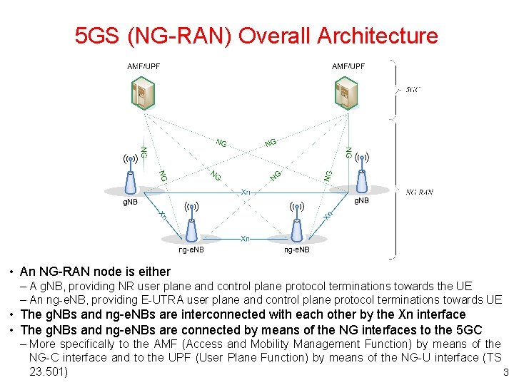
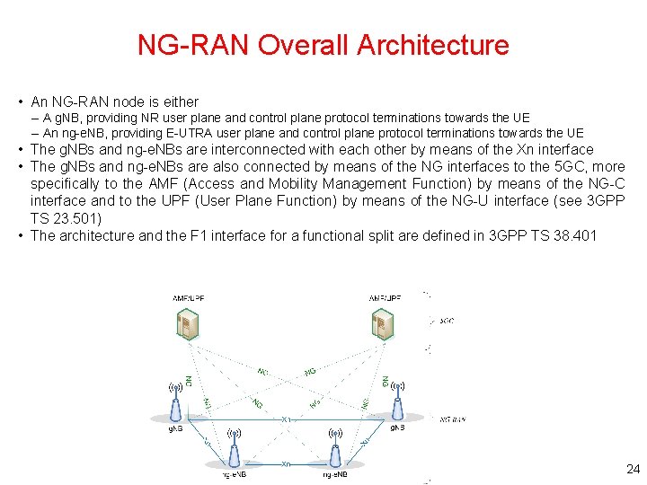
5 GS (NG-RAN) Overall Architecture • An NG-RAN node is either – A g. NB, providing NR user plane and control plane protocol terminations towards the UE – An ng-e. NB, providing E-UTRA user plane and control plane protocol terminations towards UE • The g. NBs and ng-e. NBs are interconnected with each other by the Xn interface • The g. NBs and ng-e. NBs are connected by means of the NG interfaces to the 5 GC – More specifically to the AMF (Access and Mobility Management Function) by means of the NG-C interface and to the UPF (User Plane Function) by means of the NG-U interface (TS 23. 501) 3
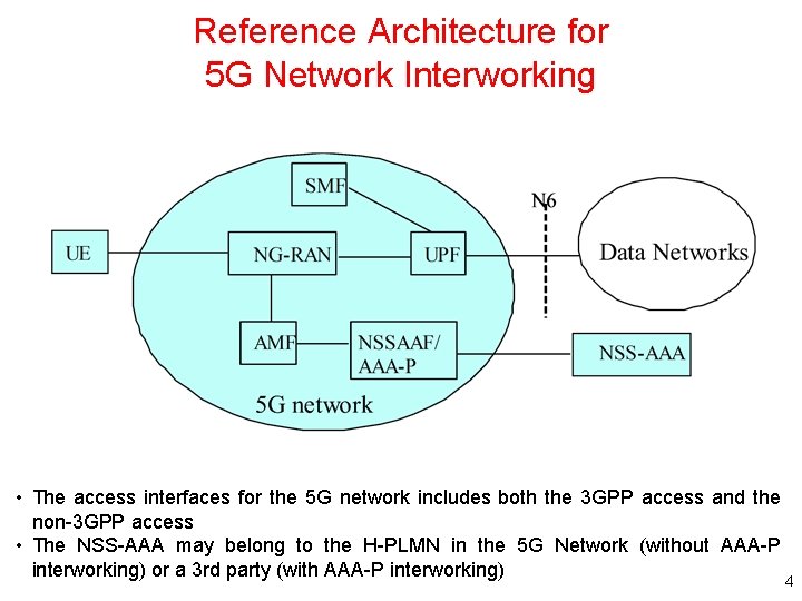
Reference Architecture for 5 G Network Interworking • The access interfaces for the 5 G network includes both the 3 GPP access and the non-3 GPP access • The NSS-AAA may belong to the H-PLMN in the 5 G Network (without AAA-P interworking) or a 3 rd party (with AAA-P interworking) 4
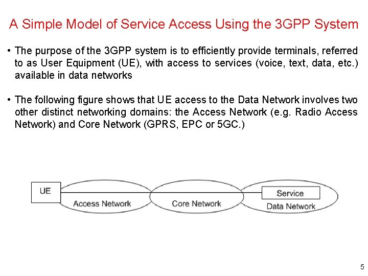
A Simple Model of Service Access Using the 3 GPP System • The purpose of the 3 GPP system is to efficiently provide terminals, referred to as User Equipment (UE), with access to services (voice, text, data, etc. ) available in data networks • The following figure shows that UE access to the Data Network involves two other distinct networking domains: the Access Network (e. g. Radio Access Network) and Core Network (GPRS, EPC or 5 GC. ) 5
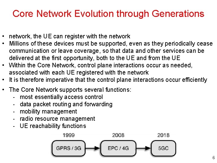
Core Network Evolution through Generations • network, the UE can register with the network • Millions of these devices must be supported, even as they periodically cease communication or leave coverage, so that data and other services can be delivered at the first opportunity, both to the UE and from the UE • Within the Core Network, control plane interactions occur as needed, associated with each UE registered with the network • It is therefore imperative that the control plane interactions occur efficiently • The Core Network supports several functions: - most essentially access control - data packet routing and forwarding - mobility management - radio resource management - UE reachability functions 6
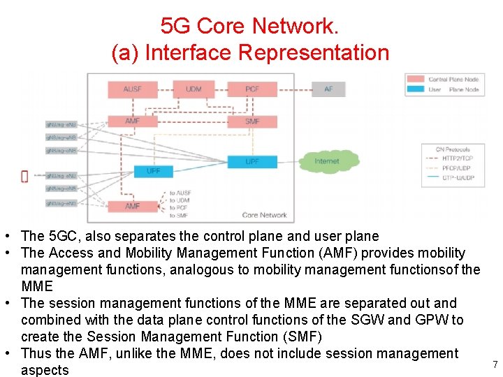
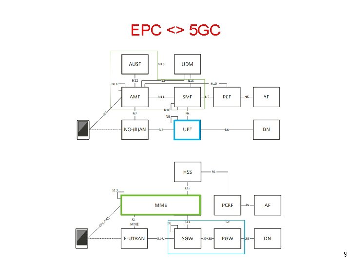
5 G Core Network. (a) Interface Representation • The 5 GC, also separates the control plane and user plane • The Access and Mobility Management Function (AMF) provides mobility management functions, analogous to mobility management functionsof the MME • The session management functions of the MME are separated out and combined with the data plane control functions of the SGW and GPW to create the Session Management Function (SMF) • Thus the AMF, unlike the MME, does not include session management aspects 7
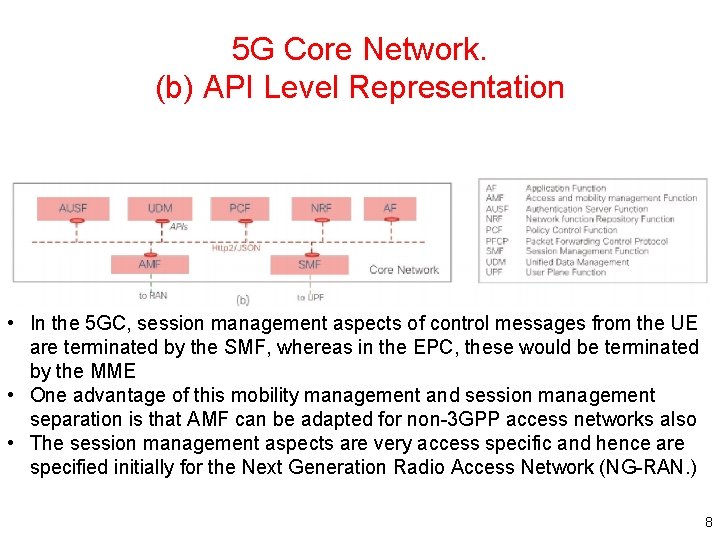
5 G Core Network. (b) API Level Representation • In the 5 GC, session management aspects of control messages from the UE are terminated by the SMF, whereas in the EPC, these would be terminated by the MME • One advantage of this mobility management and session management separation is that AMF can be adapted for non-3 GPP access networks also • The session management aspects are very access specific and hence are specified initially for the Next Generation Radio Access Network (NG-RAN. ) 8
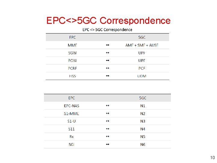
EPC <> 5 GC 9
EPC<>5 GC Correspondence 10
5 G Core Network • Another important development in successive releases is a consolidation of the number of protocols used between functions in the control plane of the system • More importantly, in 5 GC the protocol for interaction between all controlplane entities is HTTP - which is a protocol widely used in the Internet and not telecom-specific like dedicated Diameter applications or GTP-C 11
Service Based Architecture • A key advance in the 5 GC architecture is the introduction of the service based architecture • In GPRS and EPC control plane design - procedures defined all interactions between network functions as a series of message exchanges, carried out by protocol interactions • In the 5 GC - network functions employing the Service Based Architecture offer and consume services of other network functions - Allowing any other network function to consume services offered by a network function enables direct interactions between network functions • In the past, several kinds of interactions piggybacked (or reused) messages exchanged along general purpose paths, since a direct interface does not exist between the consumer and producer network function 12
Service Based Architecture (cont. ) • The Policy Control Function (PCF) - can directly subscribe to location change service offered by the AMF rather than having to have this event proxied via the SMF • In the EPC, - by contrast, analogous information followed a hop by hop path from the MME, to the SGW, to the PGW and finally the Policy and Charging Rules Function (PCRF) • There are other advantages at the protocol level - e. g. uniformity of network protocols leading to simpler implementations, use of modern transport and application protocol frameworks that are more extensible and efficient, etc. 13
State Management is an 5 GC Area • GPRS and EPC control entities defined state associated with a registered UE, called “context. ” This information, both subscription information retrieved from the HSS, and dynamic information corresponding to the registered UE is stored in the SGSN and GGSN in the GPRS architecture and the MME, SGW and PGW in the EPC • As the UE moves, the SGSN (in GPRS) or MME and SGW (in EPC) may be relocated: - new serving nodes may be selected. This procedure requires the ‘context’ to be transferred between the old and new entity, and additional state to be fetched - e. g. the subscription data to the new MME 14
State Management is an 5 GC Area (cont. ) • In the 5 GC, state may be stored centrally • This can ease network function implementations in which state storage per network function and context transfer between network functions are not desirable • In Rel-15, procedures for AMF relocation specify context transfer procedures, as in 3 G and 4 G • In future, use of centralized storage may be defined to eliminate this requirement • Also in Rel-15, the centralized Unified Data Management (UDM) function is employed for some procedures for retrieval of state - for example, in the Registration with AMF-reallocation procedure - In this procedure, per slice subscriber data including access and mobility information is stored by the initial AMF and retrieved by the target AMF 15
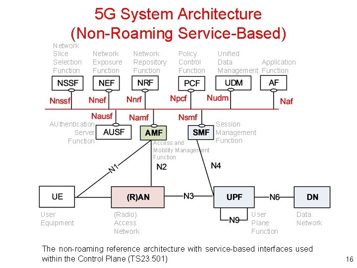
5 G System Architecture (Non-Roaming Service-Based) Network Slice Selection Function Network Exposure Function Network Repository Function AUthentication Server Function User Equipment Policy Control Function Access and Mobility Management Function (Radio) Access Network Unified Data Application Management Function Session Management Function User Plane Function Data Network The non-roaming reference architecture with service-based interfaces used within the Control Plane (TS 23. 501) 16
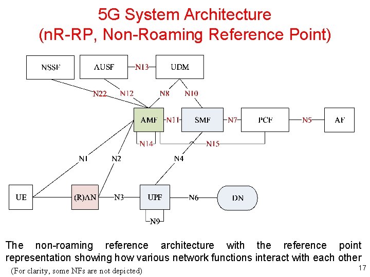
5 G System Architecture (n. R-RP, Non-Roaming Reference Point) The non-roaming reference architecture with the reference point representation showing how various network functions interact with each other (For clarity, some NFs are not depicted) 17
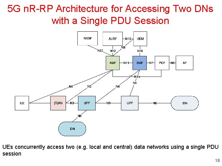
5 G n. R-RP Architecture for Accessing Two DNs with a Single PDU Session UEs concurrently access two (e. g. local and central) data networks using a single PDU session 18
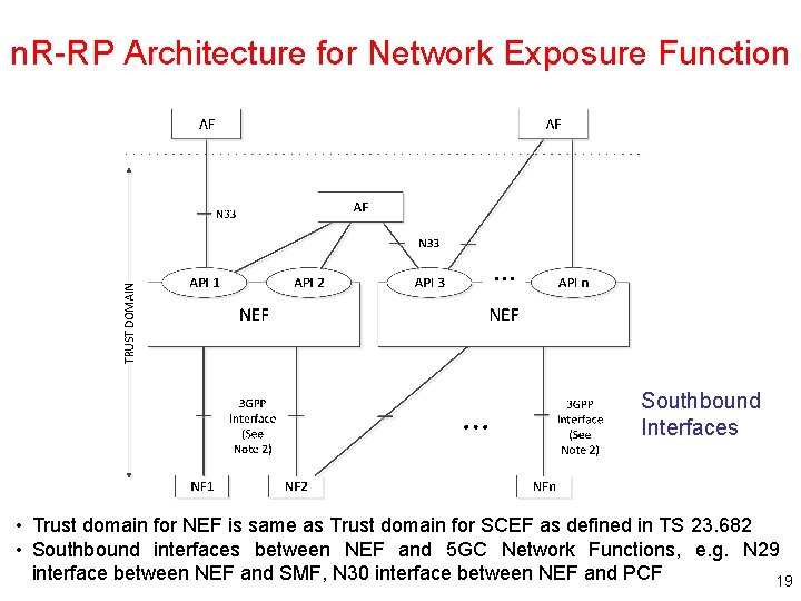
n. R-RP Architecture for Network Exposure Function Southbound Interfaces • Trust domain for NEF is same as Trust domain for SCEF as defined in TS 23. 682 • Southbound interfaces between NEF and 5 GC Network Functions, e. g. N 29 interface between NEF and SMF, N 30 interface between NEF and PCF 19
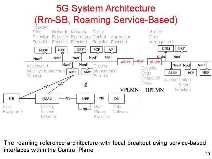
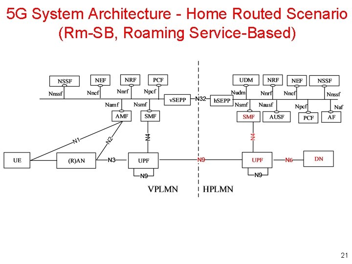
5 G System Architecture (Rm-SB, Roaming Service-Based) Network Slice Network Policy Selection Exposure Repository Control Application Function Function Access and Mobility Management Function User Equipment (Radio) Access Network Session Management Function Unified Data Management Security Edge Protection AUthentication Proxy Server Function User Data Plane Network Function The roaming reference architecture with local breakout using service-based interfaces within the Control Plane 20
5 G System Architecture - Home Routed Scenario (Rm-SB, Roaming Service-Based) 21
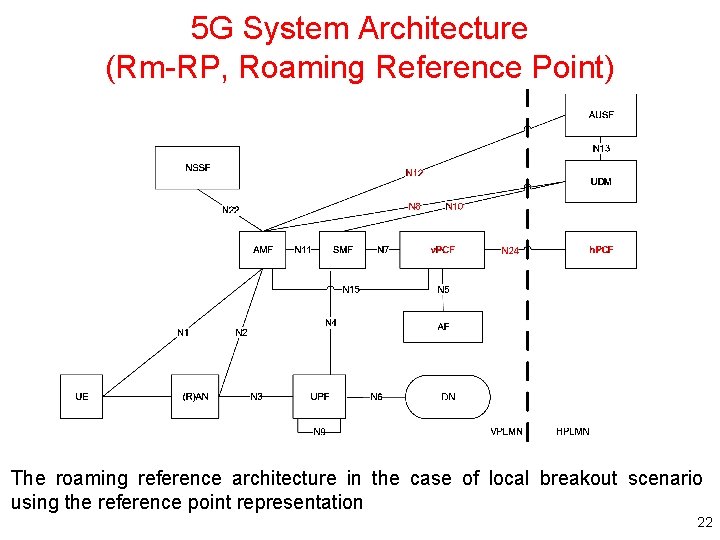
5 G System Architecture (Rm-RP, Roaming Reference Point) The roaming reference architecture in the case of local breakout scenario using the reference point representation 22
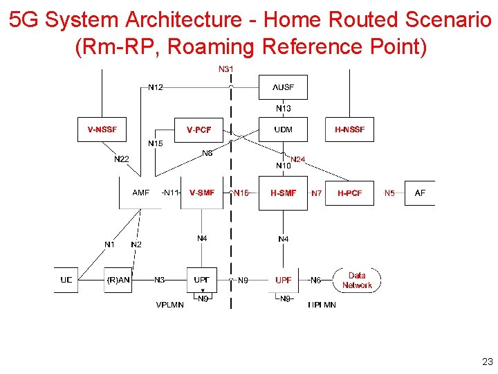
5 G System Architecture - Home Routed Scenario (Rm-RP, Roaming Reference Point) 23
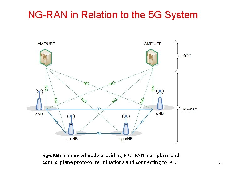
NG-RAN Overall Architecture • An NG-RAN node is either – A g. NB, providing NR user plane and control plane protocol terminations towards the UE – An ng-e. NB, providing E-UTRA user plane and control plane protocol terminations towards the UE • The g. NBs and ng-e. NBs are interconnected with each other by means of the Xn interface • The g. NBs and ng-e. NBs are also connected by means of the NG interfaces to the 5 GC, more specifically to the AMF (Access and Mobility Management Function) by means of the NG-C interface and to the UPF (User Plane Function) by means of the NG-U interface (see 3 GPP TS 23. 501) • The architecture and the F 1 interface for a functional split are defined in 3 GPP TS 38. 401 24
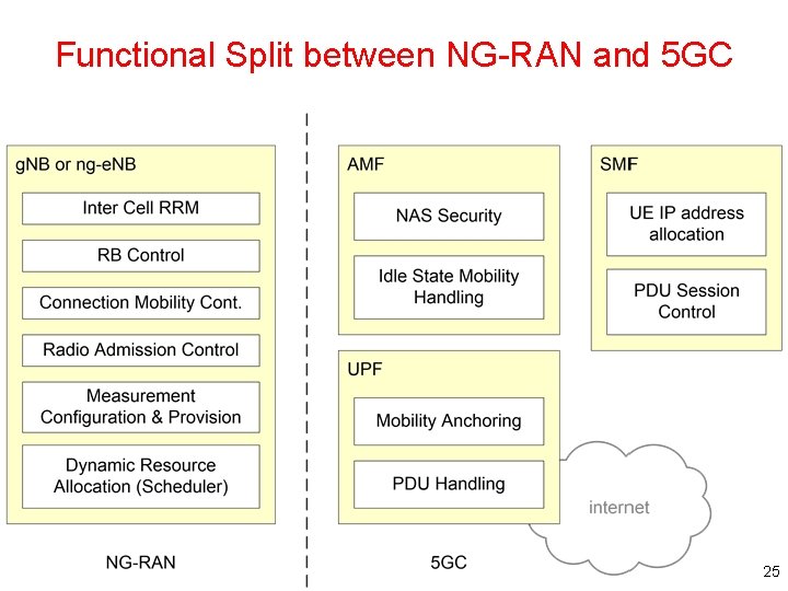
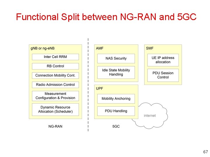
Functional Split between NG-RAN and 5 GC 25
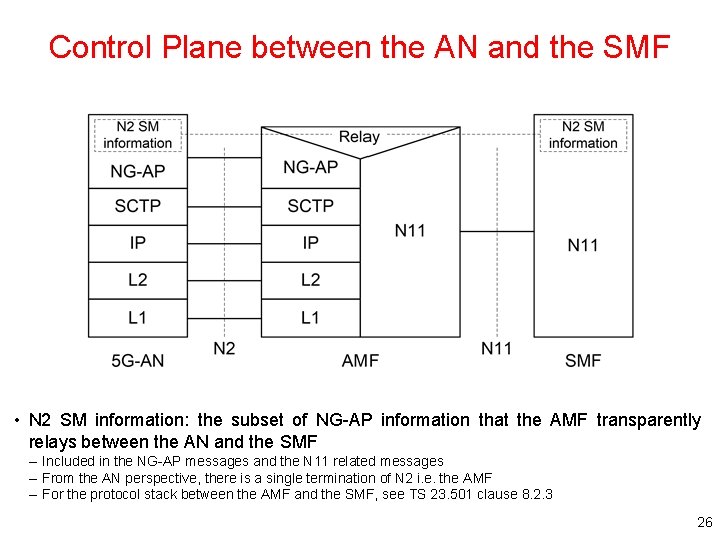
Control Plane between the AN and the SMF • N 2 SM information: the subset of NG-AP information that the AMF transparently relays between the AN and the SMF – Included in the NG-AP messages and the N 11 related messages – From the AN perspective, there is a single termination of N 2 i. e. the AMF – For the protocol stack between the AMF and the SMF, see TS 23. 501 clause 8. 2. 3 26
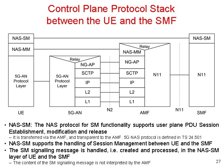
Control Plane Protocol Stack between the UE and the SMF • NAS-SM: The NAS protocol for SM functionality supports user plane PDU Session Establishment, modification and release – It is transferred via the AMF, and transparent to the AMF. 5 G NAS protocol is defined in TS 24. 501 • NAS-SM supports the handling of Session Management between UE and the SMF • The SM signalling message is handled, i. e. created and processed, in the NAS-SM layer of UE and the SMF – The content of the SM signalling message is not interpreted by the AMF 27
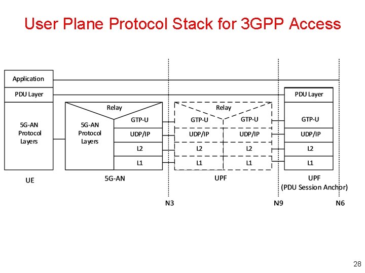
User Plane Protocol Stack for 3 GPP Access 28
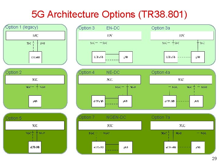
5 G Architecture Options (TR 38. 801) Option 1 (legacy) Option 3 EN-DC Option 3 a Option 2 Option 4 NE-DC Option 4 a Option 5 Option 7 NGEN-DC Option 7 a 29
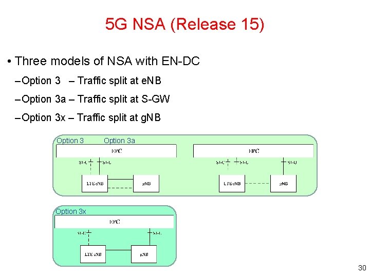
5 G NSA (Release 15) • Three models of NSA with EN-DC – Option 3 – Traffic split at e. NB – Option 3 a – Traffic split at S-GW – Option 3 x – Traffic split at g. NB Option 3 a Option 3 x 30
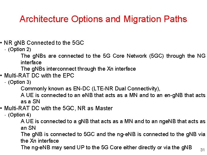
Architecture Options and Migration Paths • NR g. NB Connected to the 5 GC - (Option 2) The g. NBs are connected to the 5 G Core Network (5 GC) through the NG interface The g. NBs interconnect through the Xn interface • Multi-RAT DC with the EPC - (Option 3) Commonly known as EN-DC (LTE-NR Dual Connectivity), A UE is connected to an e. NB that acts as a MN and to an en-g. NB that acts as a SN • Multi-RAT DC with the 5 GC, NR as Master - (Option 4) A UE is connected to a g. NB that acts as a MN and to an nge. NB that acts as an SN The g. NB is connected to 5 GC and the ng-e. NB is connected to the g. NB via the Xn interface The ng-e. NB may send UP to the 5 G Core either directly or via the g. NB 31
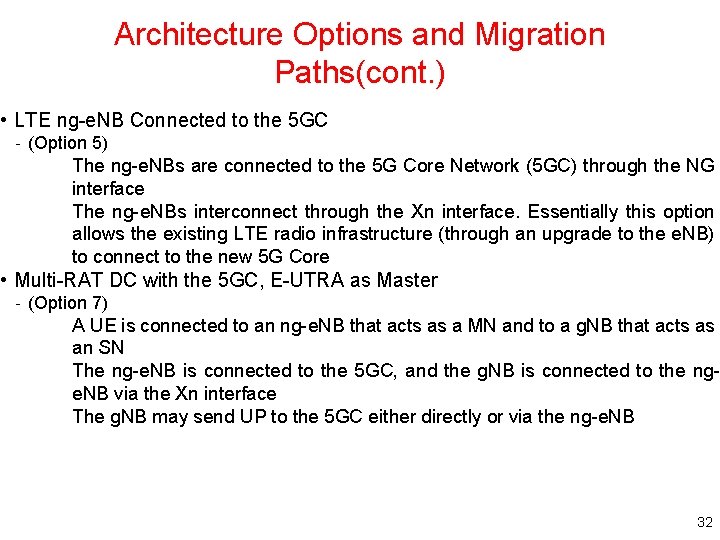
Architecture Options and Migration Paths(cont. ) • LTE ng-e. NB Connected to the 5 GC - (Option 5) The ng-e. NBs are connected to the 5 G Core Network (5 GC) through the NG interface The ng-e. NBs interconnect through the Xn interface. Essentially this option allows the existing LTE radio infrastructure (through an upgrade to the e. NB) to connect to the new 5 G Core • Multi-RAT DC with the 5 GC, E-UTRA as Master - (Option 7) A UE is connected to an ng-e. NB that acts as a MN and to a g. NB that acts as an SN The ng-e. NB is connected to the 5 GC, and the g. NB is connected to the nge. NB via the Xn interface The g. NB may send UP to the 5 GC either directly or via the ng-e. NB 32
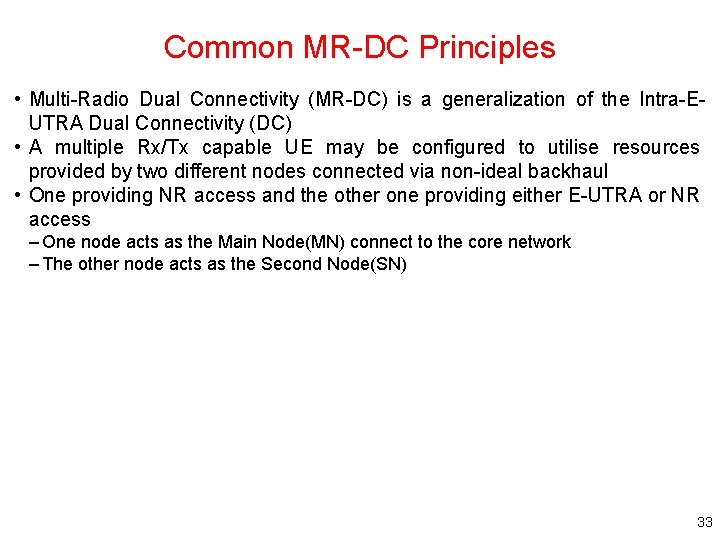
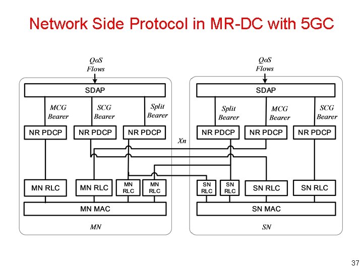
Common MR-DC Principles • Multi-Radio Dual Connectivity (MR-DC) is a generalization of the Intra-EUTRA Dual Connectivity (DC) • A multiple Rx/Tx capable UE may be configured to utilise resources provided by two different nodes connected via non-ideal backhaul • One providing NR access and the other one providing either E-UTRA or NR access – One node acts as the Main Node(MN) connect to the core network – The other node acts as the Second Node(SN) 33
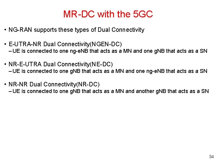
MR-DC with the 5 GC • NG-RAN supports these types of Dual Connectivity • E-UTRA-NR Dual Connectivity(NGEN-DC) – UE is connected to one ng-e. NB that acts as a MN and one g. NB that acts as a SN • NR-E-UTRA Dual Connectivity(NE-DC) – UE is connected to one g. NB that acts as a MN and one ng-e. NB that acts as a SN • NR-NR Dual Connectivity(NR-DC) – UE is connected to one g. NB that acts as a MN and another g. NB that acts as a SN 34
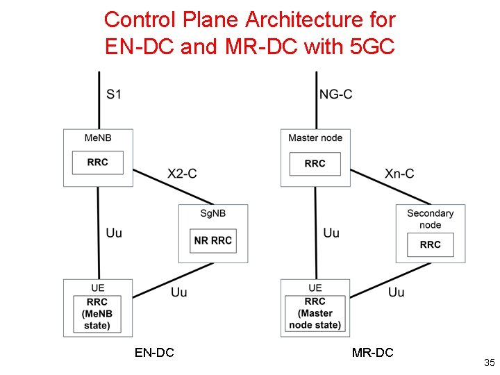
Control Plane Architecture for EN-DC and MR-DC with 5 GC EN-DC MR-DC 35
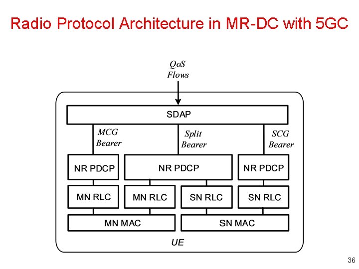
Radio Protocol Architecture in MR-DC with 5 GC 36
Network Side Protocol in MR-DC with 5 GC 37
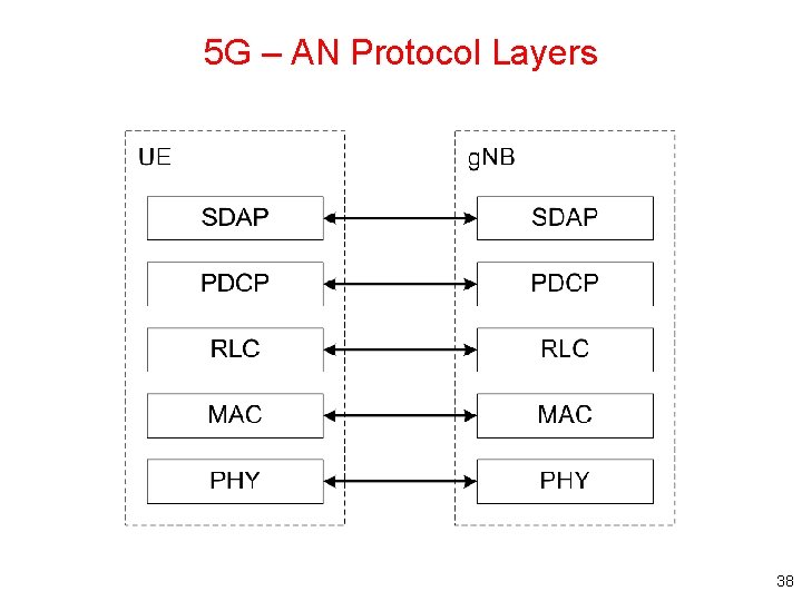
5 G – AN Protocol Layers 38
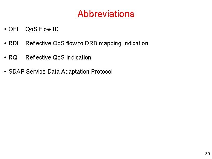
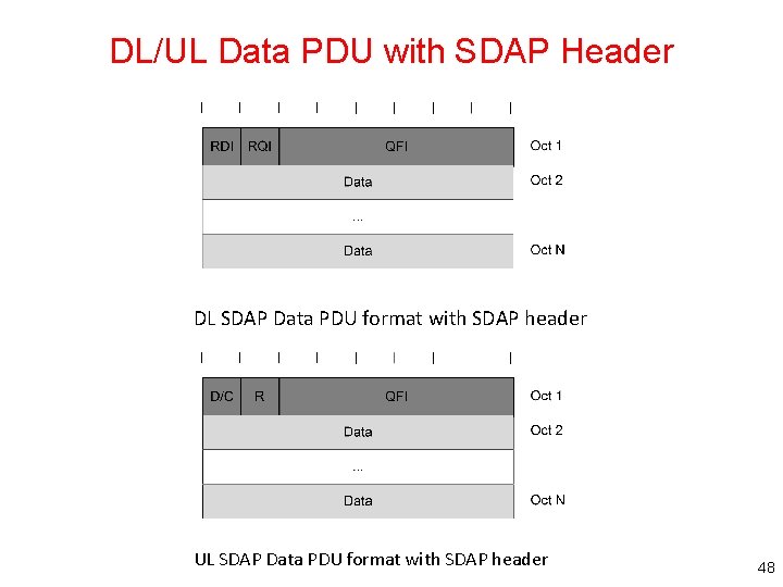
Abbreviations • QFI Qo. S Flow ID • RDI Reflective Qo. S flow to DRB mapping Indication • RQI Reflective Qo. S Indication • SDAP Service Data Adaptation Protocol 39
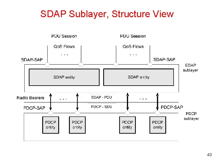
SDAP Sublayer, Structure View 40
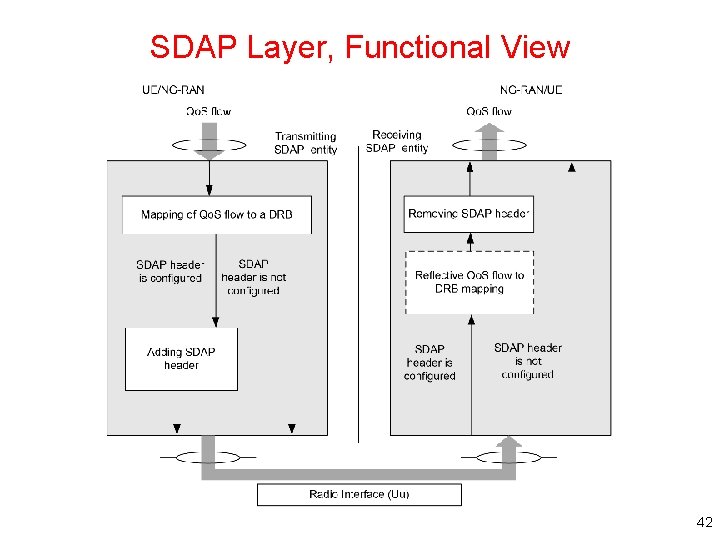
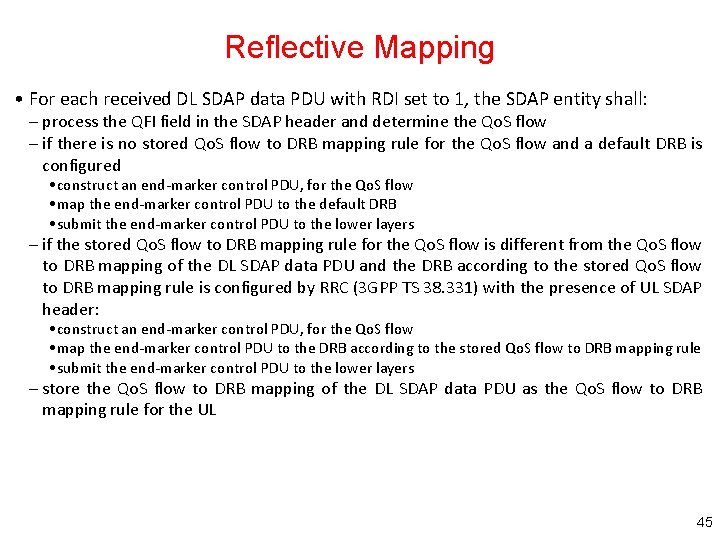
SDAP Entities • The SDAP entities are located in the SDAP sublayer. Several SDAP entities may be defined for a UE. There is an SDAP entity configured for each individual PDU session • An SDAP entity receives/delivers SDAP SDUs from/to upper layers and submits/receives SDAP data PDUs to/from its peer SDAP entity via lower layers – At the transmitting side, when an SDAP entity receives an SDAP SDU from upper layers, it constructs the corresponding SDAP data PDU and submits it to lower layers – At the receiving side, when an SDAP entity receives an SDAP data PDU from lower layers, it retrieves the corresponding SDAP SDU and delivers it to upper layers 41
SDAP Layer, Functional View 42
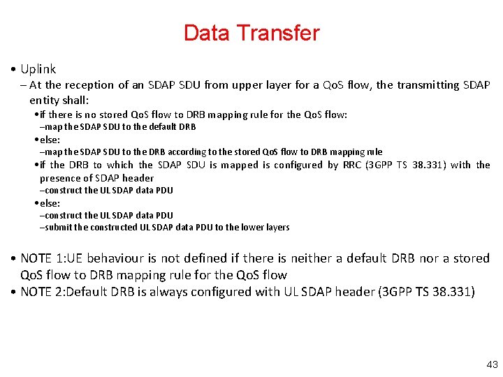
Data Transfer • Uplink – At the reception of an SDAP SDU from upper layer for a Qo. S flow, the transmitting SDAP entity shall: • if there is no stored Qo. S flow to DRB mapping rule for the Qo. S flow: –map the SDAP SDU to the default DRB • else: –map the SDAP SDU to the DRB according to the stored Qo. S flow to DRB mapping rule • if the DRB to which the SDAP SDU is mapped is configured by RRC (3 GPP TS 38. 331) with the presence of SDAP header –construct the UL SDAP data PDU • else: –construct the UL SDAP data PDU –submit the constructed UL SDAP data PDU to the lower layers • NOTE 1: UE behaviour is not defined if there is neither a default DRB nor a stored Qo. S flow to DRB mapping rule for the Qo. S flow • NOTE 2: Default DRB is always configured with UL SDAP header (3 GPP TS 38. 331) 43
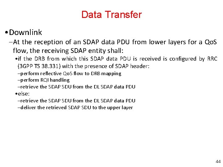
Data Transfer • Downlink – At the reception of an SDAP data PDU from lower layers for a Qo. S flow, the receiving SDAP entity shall: • if the DRB from which this SDAP data PDU is received is configured by RRC (3 GPP TS 38. 331) with the presence of SDAP header: –perform reflective Qo. S flow to DRB mapping –perform RQI handling –retrieve the SDAP SDU from the DL SDAP data PDU • else: –retrieve the SDAP SDU from the DL SDAP data PDU –deliver the retrieved SDAP SDU to the upper layer 44
Reflective Mapping • For each received DL SDAP data PDU with RDI set to 1, the SDAP entity shall: – process the QFI field in the SDAP header and determine the Qo. S flow – if there is no stored Qo. S flow to DRB mapping rule for the Qo. S flow and a default DRB is configured • construct an end-marker control PDU, for the Qo. S flow • map the end-marker control PDU to the default DRB • submit the end-marker control PDU to the lower layers – if the stored Qo. S flow to DRB mapping rule for the Qo. S flow is different from the Qo. S flow to DRB mapping of the DL SDAP data PDU and the DRB according to the stored Qo. S flow to DRB mapping rule is configured by RRC (3 GPP TS 38. 331) with the presence of UL SDAP header: • construct an end-marker control PDU, for the Qo. S flow • map the end-marker control PDU to the DRB according to the stored Qo. S flow to DRB mapping rule • submit the end-marker control PDU to the lower layers – store the Qo. S flow to DRB mapping of the DL SDAP data PDU as the Qo. S flow to DRB mapping rule for the UL 45
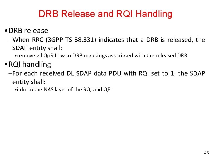
DRB Release and RQI Handling • DRB release – When RRC (3 GPP TS 38. 331) indicates that a DRB is released, the SDAP entity shall: • remove all Qo. S flow to DRB mappings associated with the released DRB • RQI handling – For each received DL SDAP data PDU with RQI set to 1, the SDAP entity shall: • inform the NAS layer of the RQI and QFI 46
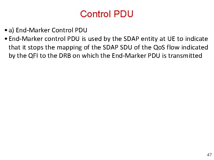
Control PDU • a) End-Marker Control PDU • End-Marker control PDU is used by the SDAP entity at UE to indicate that it stops the mapping of the SDAP SDU of the Qo. S flow indicated by the QFI to the DRB on which the End-Marker PDU is transmitted 47
DL/UL Data PDU with SDAP Header DL SDAP Data PDU format with SDAP header UL SDAP Data PDU format with SDAP header 48
Outline • 5 GC: 5 G Core Networks – Overview of Core Networks – 5 GC Architectures • NG Interface – General Aspects and Functions – Protocol Stack and Procedures 49
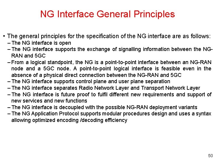
NG Interface General Principles • The general principles for the specification of the NG interface are as follows: – The NG interface is open – The NG interface supports the exchange of signalling information between the NGRAN and 5 GC – From a logical standpoint, the NG is a point-to-point interface between an NG-RAN node and a 5 GC node. A point-to-point logical interface is feasible even in the absence of a physical direct connection between the NG-RAN and 5 GC – The NG interface supports control plane and user plane separation – The NG interface separates Radio Network Layer and Transport Network Layer – The NG interface is future proof to fulfil different new requirements and support of new services and new functions – The NG interface is decoupled with the possible NG-RAN deployment variants – The NG Application Protocol supports modular procedures design and uses a syntax allowing optimized encoding /decoding efficiency 50
NG Interface Specification Objectives • The NG interface specification facilitates the following: – Inter-connection of NG-RAN nodes with AMFs supplied by different manufacturers – Separation of NG interface Radio Network functionality and Transport Network functionality to facilitate introduction of future technology 51
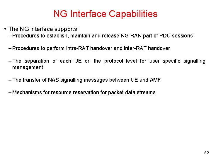
NG Interface Capabilities • The NG interface supports: – Procedures to establish, maintain and release NG-RAN part of PDU sessions – Procedures to perform intra-RAT handover and inter-RAT handover – The separation of each UE on the protocol level for user specific signalling management – The transfer of NAS signalling messages between UE and AMF – Mechanisms for resource reservation for packet data streams 52
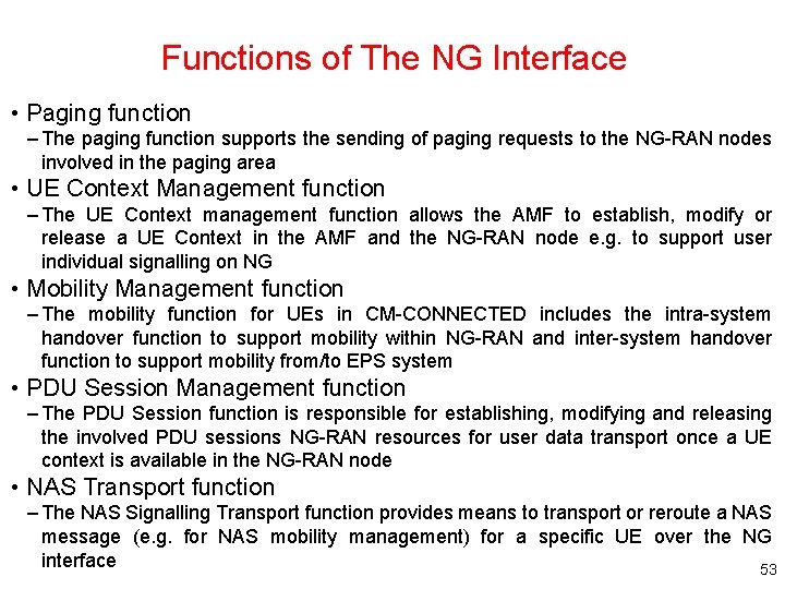
Functions of The NG Interface • Paging function – The paging function supports the sending of paging requests to the NG-RAN nodes involved in the paging area • UE Context Management function – The UE Context management function allows the AMF to establish, modify or release a UE Context in the AMF and the NG-RAN node e. g. to support user individual signalling on NG • Mobility Management function – The mobility function for UEs in CM-CONNECTED includes the intra-system handover function to support mobility within NG-RAN and inter-system handover function to support mobility from/to EPS system • PDU Session Management function – The PDU Session function is responsible for establishing, modifying and releasing the involved PDU sessions NG-RAN resources for user data transport once a UE context is available in the NG-RAN node • NAS Transport function – The NAS Signalling Transport function provides means to transport or reroute a NAS message (e. g. for NAS mobility management) for a specific UE over the NG interface 53
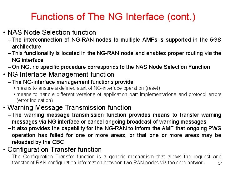
Functions of The NG Interface (cont. ) • NAS Node Selection function – The interconnection of NG-RAN nodes to multiple AMFs is supported in the 5 GS architecture – This functionality is located in the NG-RAN node and enables proper routing via the NG interface – On NG, no specific procedure corresponds to the NAS Node Selection Function • NG Interface Management function – The NG-interface management functions provide • means to ensure a defined start of NG-interface operation (reset) • means to handle different versions of application part implementations and protocol errors (error indication) • Warning Message Transmission function – The warning message transmission function provides means to transfer warning messages via NG interface or cancel ongoing broadcast of warning messages – It also provides the capability for the NG-RAN to inform the AMF that ongoing PWS operation has failed for one or more areas, or that one or more areas may be reloaded by the CBC • Configuration Transfer function – The Configuration Transfer function is a generic mechanism that allows the request and transfer of RAN configuration information between two RAN nodes via the core network 54
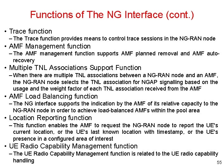
Functions of The NG Interface (cont. ) • Trace function – The Trace function provides means to control trace sessions in the NG-RAN node • AMF Management function – The AMF management function supports AMF planned removal and AMF autorecovery • Multiple TNL Associations Support Function – When there are multiple TNL associations between a NG-RAN node and an AMF, the NG-RAN node selects the TNL association for NGAP signalling based on the usage and the weight factor of each TNL association received from the AMF • AMF Load Balancing function – The NG interface supports the indication by the AMF of its relative capacity to the NG-RAN node in order to achieve load-balanced AMFs within the pool area • Location Reporting function – This function enables the AMF to request the NG-RAN node to report the UE's current location, or the UE's last known location with timestamp, or the UE's presence in a configured area of interest • UE Radio Capability Management function – The UE Radio Capability Management function is related to the UE radio capability handling 55
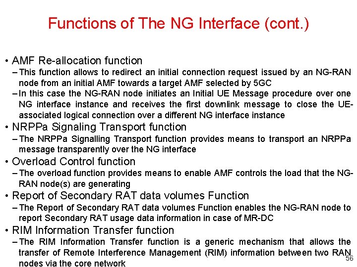
Functions of The NG Interface (cont. ) • AMF Re-allocation function – This function allows to redirect an initial connection request issued by an NG-RAN node from an initial AMF towards a target AMF selected by 5 GC – In this case the NG-RAN node initiates an Initial UE Message procedure over one NG interface instance and receives the first downlink message to close the UEassociated logical connection over a different NG interface instance • NRPPa Signaling Transport function – The NRPPa Signalling Transport function provides means to transport an NRPPa message transparently over the NG interface • Overload Control function – The overload function provides means to enable AMF controls the load that the NGRAN node(s) are generating • Report of Secondary RAT data volumes Function – The Report of Secondary RAT data volumes Function enables the NG-RAN node to report Secondary RAT usage data information in case of MR-DC • RIM Information Transfer function – The RIM Information Transfer function is a generic mechanism that allows the transfer of Remote Interference Management (RIM) information between two RAN 56 nodes via the core network
NG-U Protocol Stack • The NG user plane interface (NG-U) is defined between the NG-RAN node and the UPF The user plane protocol stack of the NG interface The transport network layer is built on IP transport and GTP-U is used on top of UDP/IP to carry the user plane PDUs between the NG-RAN node and the UPF • NG-U provides non-guaranteed delivery of user plane PDUs between 57 the NG-RAN node and the UPF
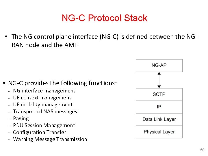
NG-C Protocol Stack • The NG control plane interface (NG-C) is defined between the NGRAN node and the AMF • NG-C provides the following functions: NG interface management UE context management UE mobility management Transport of NAS messages Paging PDU Session Management Configuration Transfer Warning Message Transmission 58
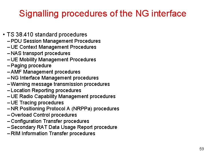
Signalling procedures of the NG interface • TS 38. 410 standard procedures – PDU Session Management Procedures – UE Context Management Procedures – NAS transport procedures – UE Mobility Management Procedures – Paging procedure – AMF Management procedures – NG Interface Management procedures – Warning message transmission procedures – Location Reporting procedures – UE Radio Capability Management procedures – UE Tracing procedures – NR Positioning Protocol A (NRPPa) procedures – Overload Control procedures – Configuration Transfer procedures – Secondary RAT Data Usage Report procedure – RIM Information Transfer procedures 59
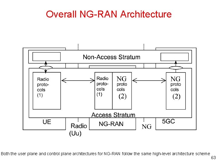
Overview of the NG-RAN Architecture • The NG-RAN represents the newly defined radio access network for 5 G – NG-RAN provides both NR and LTE radio access • An NG-RAN node (i. e. base station) is either - A g. NB (i. e. a 5 G base station), providing NR user plane and control plane services - An ng-e. NB, providing LTE/E-UTRAN services towards the UE 60
NG-RAN in Relation to the 5 G System ng-e. NB: enhanced node providing E-UTRAN user plane and control plane protocol terminations and connecting to 5 GC 61
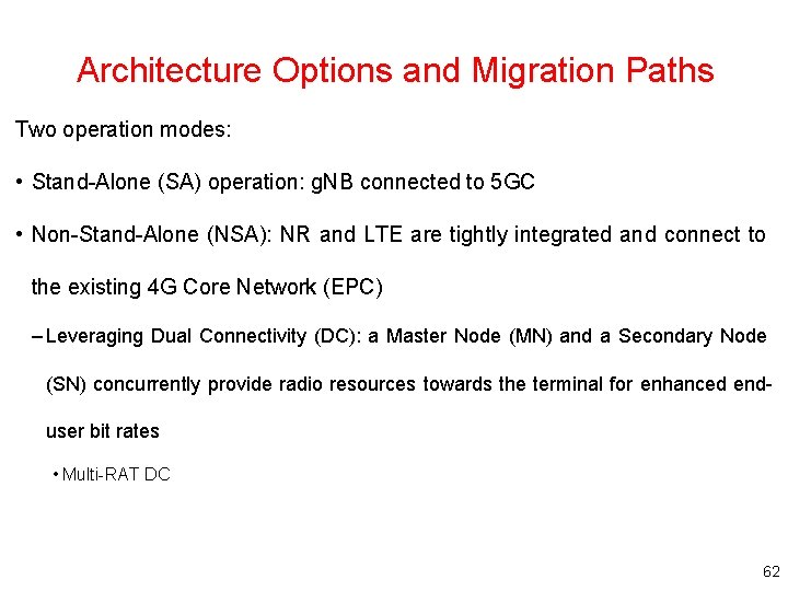
Architecture Options and Migration Paths Two operation modes: • Stand-Alone (SA) operation: g. NB connected to 5 GC • Non-Stand-Alone (NSA): NR and LTE are tightly integrated and connect to the existing 4 G Core Network (EPC) – Leveraging Dual Connectivity (DC): a Master Node (MN) and a Secondary Node (SN) concurrently provide radio resources towards the terminal for enhanced enduser bit rates • Multi-RAT DC 62
Overall NG-RAN Architecture Both the user plane and control plane architectures for NG-RAN follow the same high-level architecture scheme 63
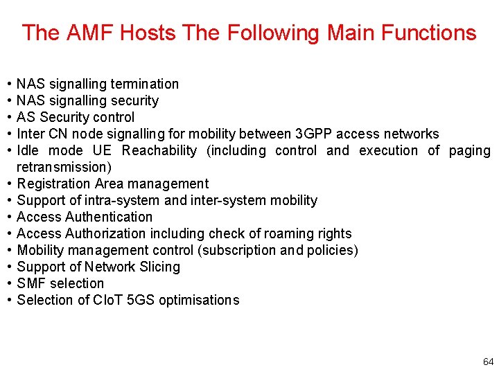
The AMF Hosts The Following Main Functions • • • • NAS signalling termination NAS signalling security AS Security control Inter CN node signalling for mobility between 3 GPP access networks Idle mode UE Reachability (including control and execution of paging retransmission) Registration Area management Support of intra-system and inter-system mobility Access Authentication Access Authorization including check of roaming rights Mobility management control (subscription and policies) Support of Network Slicing SMF selection Selection of CIo. T 5 GS optimisations 64
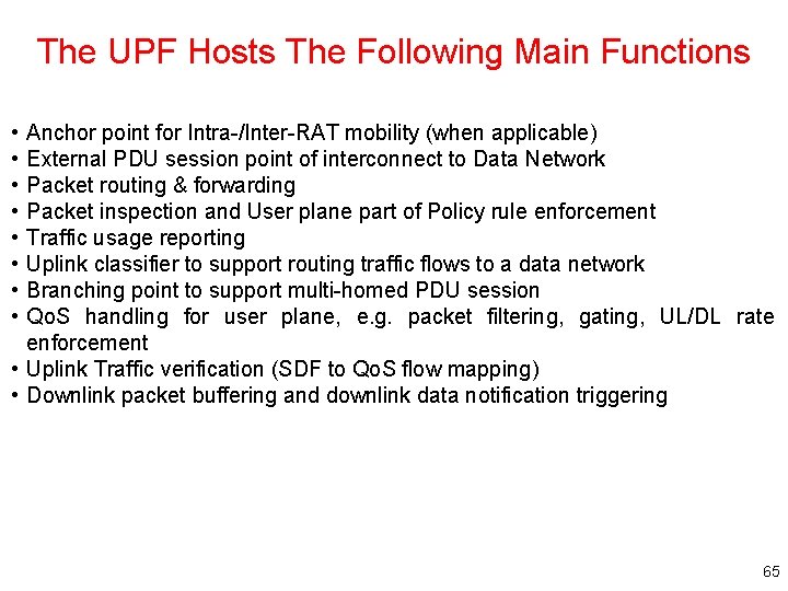
The UPF Hosts The Following Main Functions • • Anchor point for Intra-/Inter-RAT mobility (when applicable) External PDU session point of interconnect to Data Network Packet routing & forwarding Packet inspection and User plane part of Policy rule enforcement Traffic usage reporting Uplink classifier to support routing traffic flows to a data network Branching point to support multi-homed PDU session Qo. S handling for user plane, e. g. packet filtering, gating, UL/DL rate enforcement • Uplink Traffic verification (SDF to Qo. S flow mapping) • Downlink packet buffering and downlink data notification triggering 65
The SMF Hosts The Following Main Functions • Session Management • UE IP address allocation and management • Selection and control of UP function • Configures traffic steering at UPF to route traffic to proper destination • Control part of policy enforcement and Qo. S • Downlink Data Notification 66
Functional Split between NG-RAN and 5 GC 67
Summary • Introduction to Core Networks • 5 GC – Service-based architecture – 5 GC overview • NG Interface – General principle – Functions – Protocol stack and procedures 68