
Outline 1 Novel MIM Implementation of CRLH Structure
- Slides: 18
Outline 1. Novel MIM Implementation of CRLH Structure 2. Electronically-Scanned 1 D Leaky-Wave Antenna 3. 2 D Leaky-Wave Antenna 4. 3 D LH Metamaterial 5. RH/LH Surface Plasmons Microwave Electronics Lab
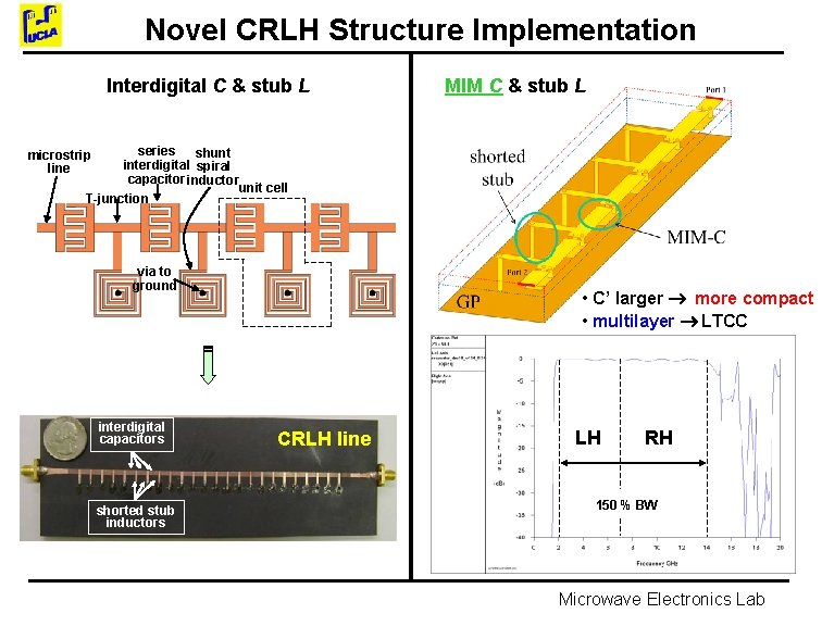
Novel CRLH Structure Implementation Interdigital C & stub L MIM C & stub L series shunt interdigital spiral capacitor inductor unit cell T-junction microstrip line via to ground interdigital capacitors shorted stub inductors • C’ larger more compact • multilayer LTCC CRLH line LH RH 150 % BW Microwave Electronics Lab
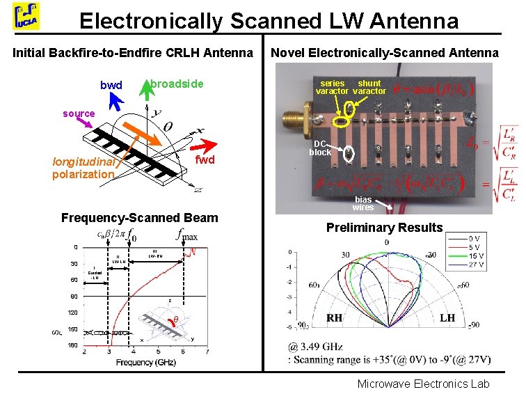
Electronically Scanned LW Antenna Initial Backfire-to-Endfire CRLH Antenna broadside bwd Novel Electronically-Scanned Antenna series shunt varactor source fwd longitudinal polarization Frequency-Scanned Beam 0 30 60 DC block bias wires Preliminary Results III. LW-RH II. LW-LH I. Guided -LH 90 z 120 θ 150 180 x y Microwave Electronics Lab
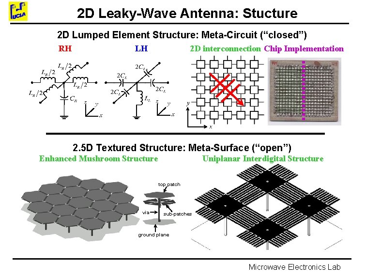
2 D Leaky-Wave Antenna: Stucture 2 D Lumped Element Structure: Meta-Circuit (“closed”) RH LH 2 D interconnection Chip Implementation 2. 5 D Textured Structure: Meta-Surface (“open”) Enhanced Mushroom Structure Uniplanar Interdigital Structure top patch via sub-patches ground plane Microwave Electronics Lab
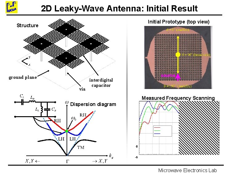
2 D Leaky-Wave Antenna: Initial Result Initial Prototype (top view) Structure ground plane via interdigital capacitor source Measured Frequency Scanning Dispersion diagram Microwave Electronics Lab
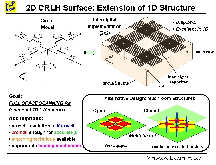
2 D CRLH Surface: Extension of 1 D Structure Circuit Model Interdigital Implementation (2 x 2) • Uniplanar • Excellent in 1 D substrate ground plane Goal: FULL SPACE SCANNING for functional 2 D LW antenna via interdigital capacitor Alternative Design: Mushroom Structures Open Closed Assumptions: • model solution to Maxwell • small enough for accurate • matching technique available • appropriate feeding mechanism Multiplanar ! Sievenpiper can include radiating slots Microwave Electronics Lab
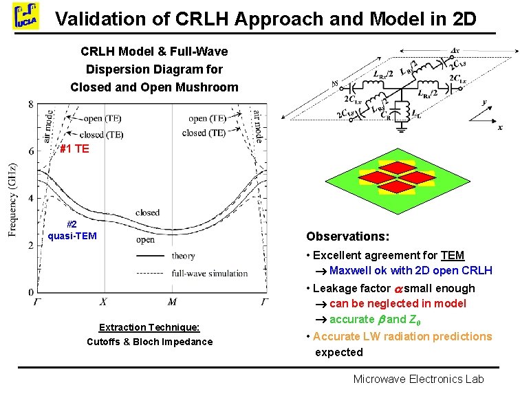
Validation of CRLH Approach and Model in 2 D CRLH Model & Full-Wave Dispersion Diagram for Closed and Open Mushroom #1 TE #2 quasi-TEM Observations: • Excellent agreement for TEM Maxwell ok with 2 D open CRLH Extraction Technique: Cutoffs & Bloch Impedance • Leakage factor small enough can be neglected in model accurate and Z 0 • Accurate LW radiation predictions expected Microwave Electronics Lab
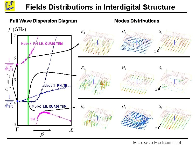
Fields Distributions in Interdigital Structure Full Wave Dispersion Diagram Modes Distributions Mode 4: RH, LH, QUADI-TEM Mode 3: RH, TE Mode 2: LH, QUADI-TEM TM Microwave Electronics Lab
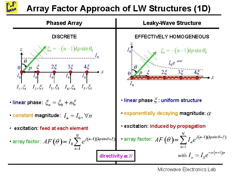
Array Factor Approach of LW Structures (1 D) Phased Array Leaky-Wave Structure DISCRETE EFFECTIVELY HOMOGENEOUS • linear phase: • linear phase • constant magnitude: • exponentially decaying magnitude: • excitation: feed at each element • excitation: induced by propagation • array factor: : uniform structure directivity N Microwave Electronics Lab
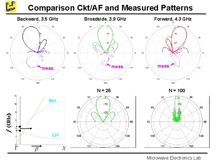
Comparison Ckt/AF and Measured Patterns Backward, 3. 5 GHz Broadside, 3. 9 GHz meas. N = 25 Forward, 4. 3 GHz meas. N = 100 RH LH Microwave Electronics Lab
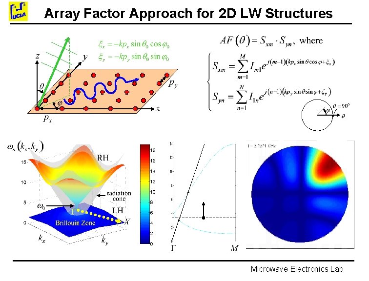
Array Factor Approach for 2 D LW Structures Microwave Electronics Lab
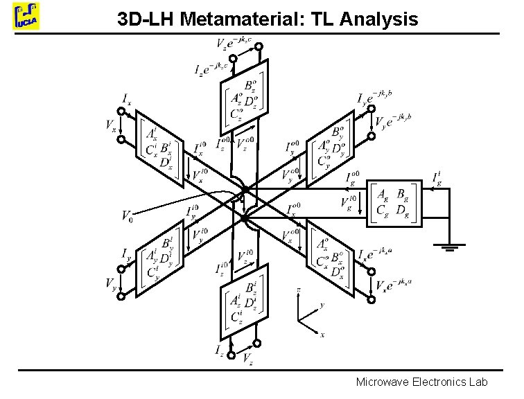
3 D-LH Metamaterial: TL Analysis Microwave Electronics Lab
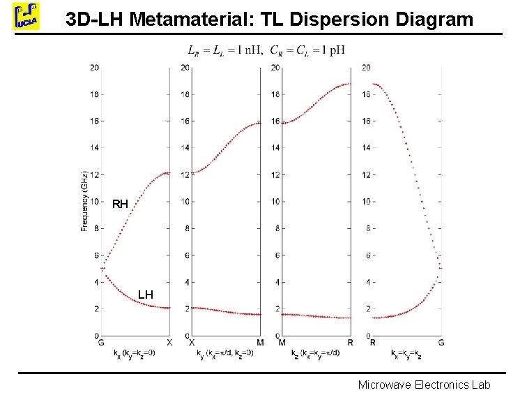
3 D-LH Metamaterial: TL Dispersion Diagram RH LH Microwave Electronics Lab
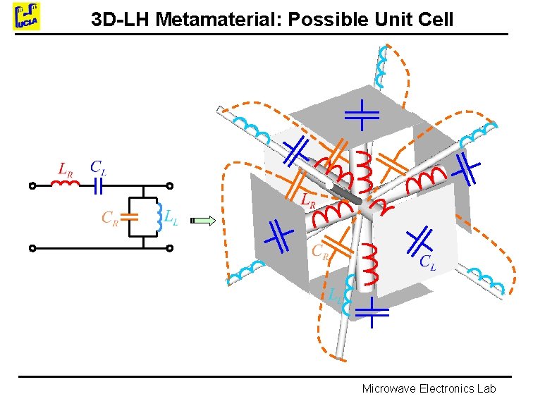
3 D-LH Metamaterial: Possible Unit Cell Microwave Electronics Lab
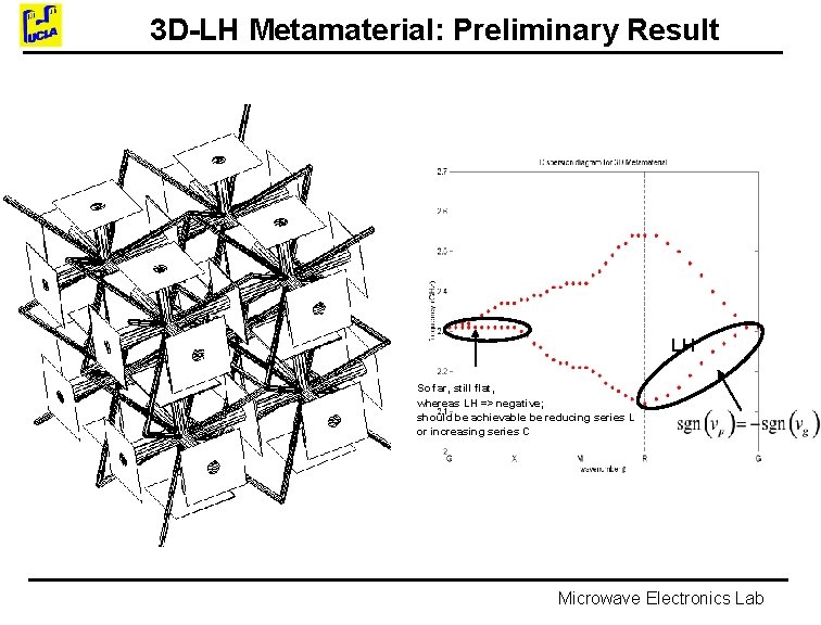
3 D-LH Metamaterial: Preliminary Result LH So far, still flat, whereas LH => negative; should be achievable be reducing series L or increasing series C Microwave Electronics Lab
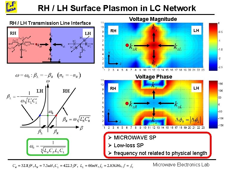
RH / LH Surface Plasmon in LC Network Voltage Magnitude RH / LH Transmission Line Interface RH LH LH RH Voltage Phase LH RH RH LH Ø MICROWAVE SP Ø Low-loss SP Ø frequency not related to physical length Microwave Electronics Lab
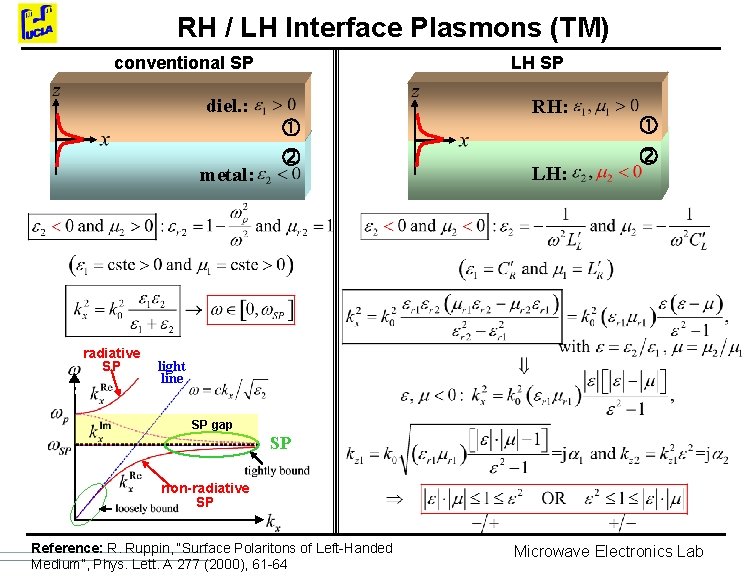
RH / LH Interface Plasmons (TM) conventional SP LH SP diel. : RH: metal: radiative SP LH: light line SP gap SP non-radiative SP Reference: R. Ruppin, “Surface Polaritons of Left-Handed Medium”, Phys. Lett. A 277 (2000), 61 -64 Microwave Electronics Lab
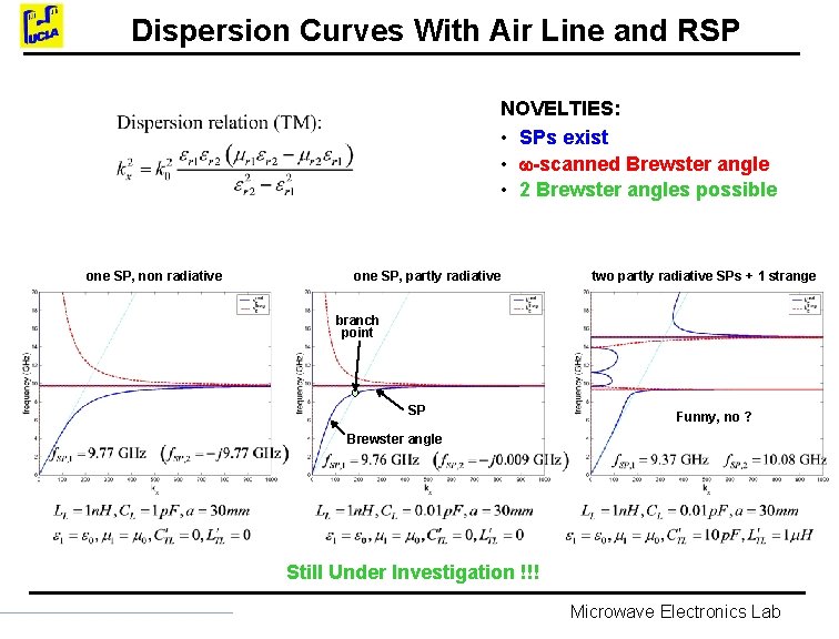
Dispersion Curves With Air Line and RSP NOVELTIES: • SPs exist • -scanned Brewster angle • 2 Brewster angles possible one SP, non radiative one SP, partly radiative two partly radiative SPs + 1 strange branch point SP Funny, no ? Brewster angle Still Under Investigation !!! Microwave Electronics Lab