OTTO CYCLE THE IDEAL CYCLE FOR SPARKIGNITION ENGINES


 engines • Compression-ignition (CI)")


 temperatures 2. Increasing")

 Propulsive efficiency Propulsive power 39")
- Slides: 39
OTTO CYCLE: THE IDEAL CYCLE FOR SPARK-IGNITION ENGINES
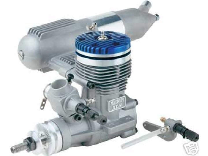
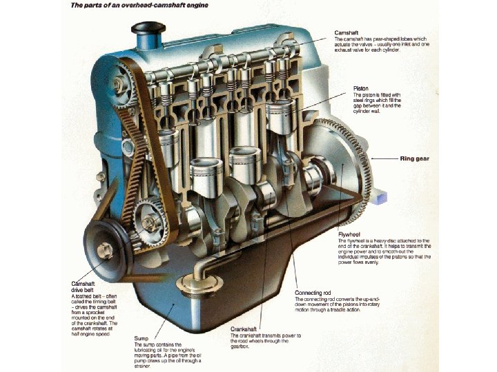
AN OVERVIEW OF RECIPROCATING ENGINES Compression ratio • Spark-ignition (SI) engines • Compression-ignition (CI) engines
In SI engines, the compression ratio is limited by autoignition or engine knock. Thermal efficiency of the ideal Diesel cycle as a function of compression and cutoff ratios (k=1. 4). Cutoff ratio
Mean effective pressure The mean effective pressure can be used as a parameter to compare the performances of reciprocating engines of equal size. The engine with a larger value of MEP delivers more net work per cycle and thus performs better.
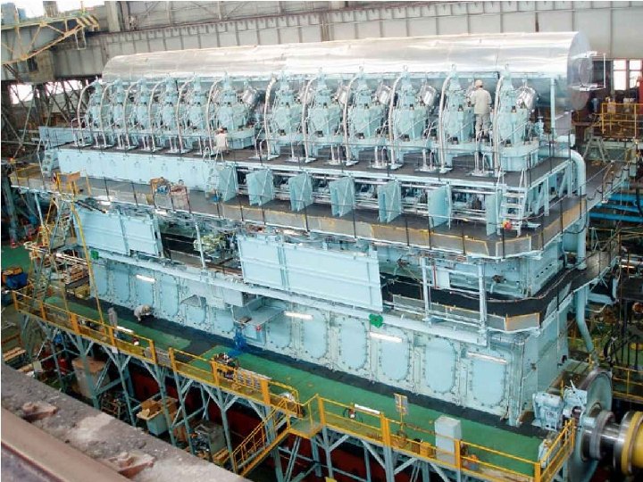
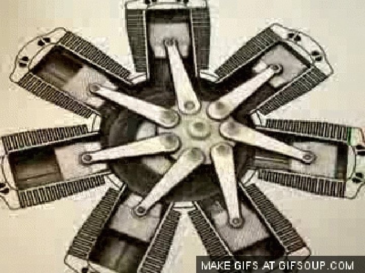
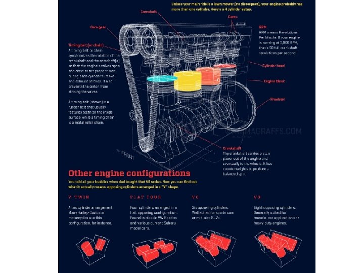
Four-stroke cycle 1 cycle = 4 stroke = 2 revolution Two-stroke cycle 1 cycle = 2 stroke = 1 revolution The two-stroke engines are generally less efficient than their four-stroke counterparts but they are relatively simple and inexpensive, and they have high power-to-weight and power-to-volume ratios. Schematic of a two-stroke reciprocating engine.
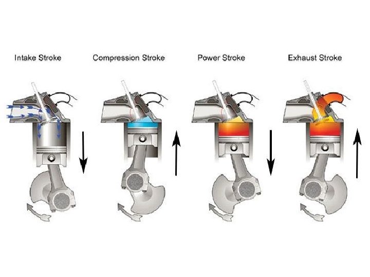
Air enters the cylinder through the open intake valve at atmospheric pressure P 0 during process 0 -1 as the piston moves from TDC to BDC. The intake valve is closed at state 1 and air is compressed isentropically to state 2. Heat is transferred at constant volume (process 2 -3); it is expanded isentropically to state 4; and heat is rejected at constant volume (process 4 -1). Air is expelled through the open exhaust valve (process 1 -0). Work interactions during intake and exhaust cancel each other, and thus inclusion of the intake and exhaust processes has no effect on the net work output from the cycle. However, when calculating power output from the cycle during an ideal Otto cycle analysis, we must consider the fact that the ideal Otto cycle has four strokes just like actual four-stroke sparkignition engine.
In SI engines, the compression ratio is limited by autoignition or engine knock. 30
DIESEL CYCLE: THE IDEAL CYCLE FOR COMPRESSION-IGNITION ENGINES In diesel engines, only air is compressed during the compression stroke, eliminating the possibility of autoignition (engine knock). Therefore, diesel engines can be designed to operate at much higher compression ratios than SI engines, typically between 12 and 24. 1 -2 isentropic compression 2 -3 constantvolume heat addition 3 -4 isentropic expansion 4 -1 constantvolume heat rejection.
Cutoff ratio for the same compression ratio Thermal efficiency of the ideal Diesel cycle as a function of compression and cutoff ratios (k=1. 4).
BRAYTON CYCLE: THE IDEAL CYCLE FOR GASTURBINE ENGINES The combustion process is replaced by a constant-pressure heat-addition process from an external source, and the exhaust process is replaced by a constant-pressure heat-rejection process to the ambient air. 1 -2 Isentropic compression (in a compressor) 2 -3 Constant-pressure heat addition 3 -4 Isentropic expansion (in a turbine) 4 -1 Constant-pressure heat rejection
Pressure ratio
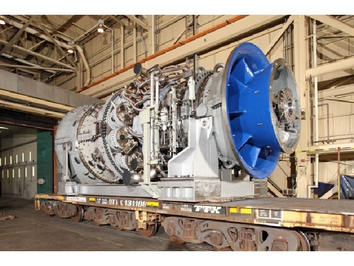
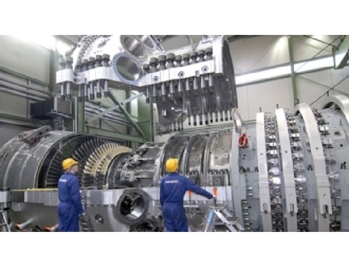
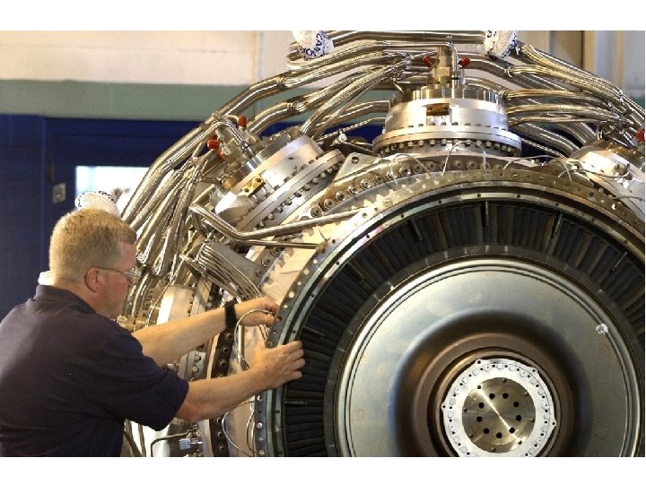
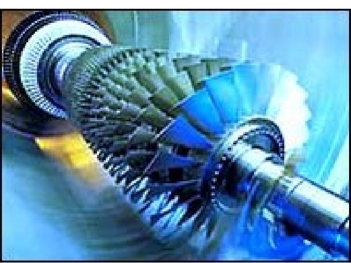
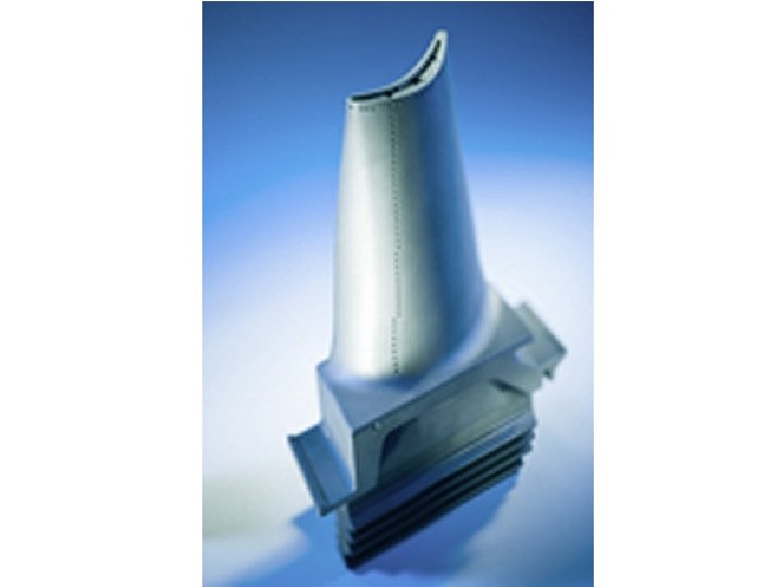
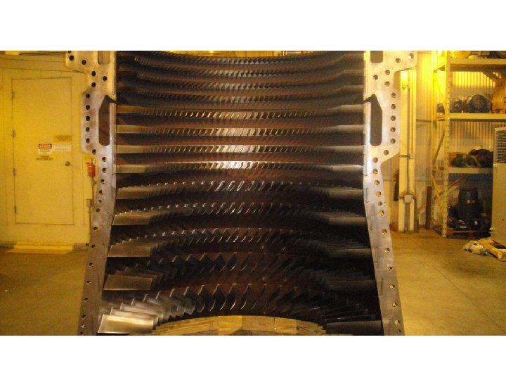
The two major application areas of gasturbine engines are aircraft propulsion and electric power generation. The highest temperature in the cycle is limited by the maximum temperature that the turbine blades can withstand. This also limits the pressure ratios that can be used in the cycle. The air in gas turbines supplies the necessary oxidant for the combustion of the fuel, and it serves as a coolant to keep the temperature of various components within safe limits. An air–fuel ratio of 50 or above is not uncommon.
Development of Gas Turbines 1. Increasing the turbine inlet (or firing) temperatures 2. Increasing the efficiencies of turbomachinery components (turbines, compressors): 3. Adding modifications to the basic cycle (intercooling, regeneration or recuperation, and reheating). Deviation of Actual Gas-Turbine Cycles from Idealized Ones Reasons: Irreversibilities in turbine and compressors, pressure drops, heat losses Isentropic efficiencies of the compressor and turbine
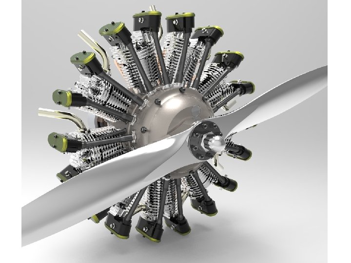
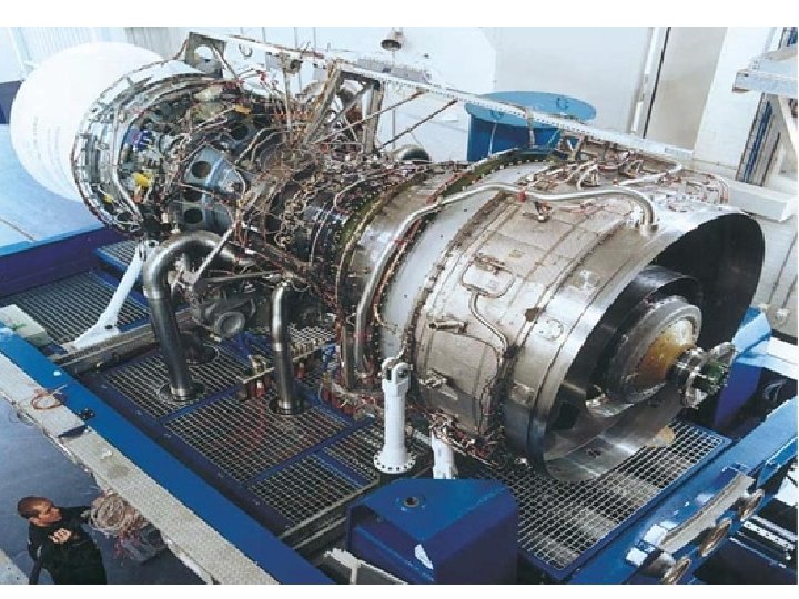
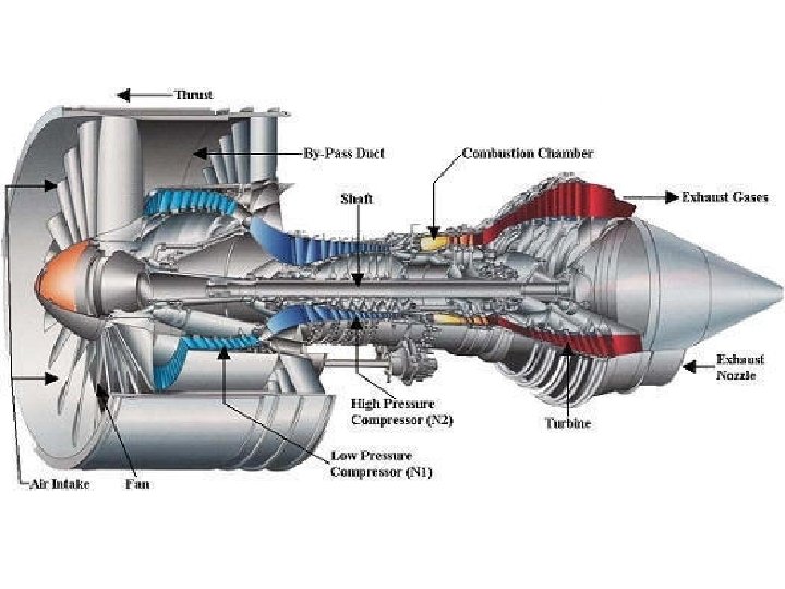
IDEAL JET-PROPULSION CYCLES Gas-turbine engines are widely used to power aircraft because they are light and compact and have a high power-to-weight ratio. Aircraft gas turbines operate on an open cycle called a jet-propulsion cycle. The ideal jet-propulsion cycle differs from the simple ideal Brayton cycle in that the gases are not expanded to the ambient pressure in the turbine. Instead, they are expanded to a pressure such that the power produced by the turbine is just sufficient to drive the compressor and the auxiliary equipment. The net work output of a jet-propulsion cycle is zero. The gases that exit the turbine at a relatively high pressure are subsequently accelerated in a nozzle to provide thrust to propel the aircraft. Aircraft are propelled by accelerating a fluid in the opposite direction to motion. This is accomplished by either slightly accelerating a large mass of fluid (propeller-driven engine) or greatly accelerating a small mass of fluid (jet or turbojet engine) or both (turboprop engine).
Thrust (propulsive force) Propulsive efficiency Propulsive power 39