Other Types of Dislocations in FCC Sessile or


- Slides: 22

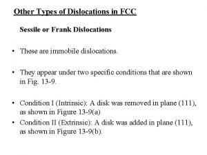
Other Types of Dislocations in FCC Sessile or Frank Dislocations • These are immobile dislocations. • They appear under two specific conditions that are shown in Fig. 13 -9. • Condition I (Intrinsic): A disk was removed in plane (111), as shown in Figure 13 -9(a) • Condition II (Extrinsic): A disk was added in plane (111), as shown in Figure 13 -9(b).

(a) (b) Figure 13 -9 (a & b). A Frank partial dislocation or sessile dislocation.

Figure 13 -9 (c). A Frank partial dislocation or sessile dislocation.

• It can be seen that in both cases the stacking sequence was changed from ABCABCABC to ABCBCA and ABCBABC for Fig. 13 -9, respectively. • The magnitude of the Burgers vector is determined by applying: (13. 6) • The Burgers vector is expressed as:

• In Thompson’s tetrahedron Figure 13 -10, the Frank dislocations are represented by • Since the Burgers vector is not in the slip plane, they are immobile.

Figure 13 -10(a). Thompson tetrahedron, the vertices are points (011), (101), (110), (000),

Figure 13 -10(b). Thompson tetrahedron, with all dislocations indicated.

Lomer-Cottrell Lock • Another type of immobile dislocation that can occur in FCC metals is the Lomer-Cottrell lock. • Let us consider two (111) and planes that are represented by , respectively, in Thompson’s tetrahedron of Figure 13 -10. • The three perfect dislocations in (111) are

• For plane , the dislocations are: • One good rule to determine whether a direction belongs to a plane is: the scalar product between the direction b and the normal to the plane has to be zero ( in a cubic structure). This rule comes from vector calculus.

• b 1 and b 4 have the same direction and opposite senses; the common direction is also that of the intersection of the two planes. Hence, both dislocations will cancel when they encounter each other. • The combination of b 2 and b 5 result in • The energy of these dislocations is: • Therefore, this reaction will not occur, because it would not result in a reduction of the energy.

• The sole combinations that would result in a decrease in the overall energy would be of the type: • This reaction is energetically favorable; it is shown in Figure 13 -11.

Figure 13 -11. Lomer-Cottrell barrier

• This dislocation is not mobile in either the (111) or plane ; hence, it acts as a barrier for any additional dislocation moving in these planes. • It impedes slip and is therefore called a “lock. ” • It was initially proposed by Lomer. • Cottrell later showed that the same reasoning could be applied to partial dislocations ( also known as Shockley partials)

• The resultant configuration is shown in Fig 13 -11; it resembles a stair and is therefore called “ stair-rod” dislocation. • The leading partials react and immobilize the partials coupled to them (trailing partials). • Its Burgers vector lying in the (100) plane normal to the line of intersecting so it is pure edge dislocation. Since (100) is not a close-packed slip plane in the fcc lattice, this dislocation will not glide freely.

• The bands of stacking faults form a configuration resembling steps on a stairway. • These steps are barriers to further slip on the atomic planes involved, as well as in the adjacent planes. • The dislocation is sessile because its Burgers vector does not lie in either of the planes of its stacking faults. • However, it is not a true sessile dislocation in the sense of the Frank partial because it is not an imperfect dislocation.

• Lomer-Cottrell barriers can be overcome at high stresses and/or temperatures. • However, it has been shown that for the important case of screw dislocations can escape the pile-up by cross slip before the stress is high enough to collapse the barrier. • While the formation of Lomer-Cottrell barriers is an important mechanism in the strain hardening of fcc metals, they do not constitute the chief contribution to strain hardening.

Dislocations In the Body-Centered Cubic Lattice • In BCC crystals the atoms are closest to each other along the <111> directions. • Any plane in the BCC crystal that contains this direction is a suitable slip plane. • Slip has been experimentally observed in (110), (112) and (123) planes. • The following reaction has been suggested for a perfect dislocation having its Burgers vector along <111>:

• This corresponds to the equivalent of Shockley partials. • Apparently, the stacking fault energy is very high, because they cannot be observed by TEM. • The waviness of the slip markings is also indicative of the high stacking fault energy. • If the partials were well separated, slip would be limited to one plane. • Recall - Cross-slip is much easier when the stacking fault is very high.

Dislocations In the Body-Centered Cubic Lattice Figure 13 -12. Slip on intersecting planes.

Example: • Show that a dislocation in a BCC structure with a Burgers vector equal to a <110> is energetically unstable and will split in to two a/2 <111> dislocations by the following reaction:

• For the above reaction to take place the energy of the a<110> dislocation must be greater than the sum of the energies of two a/2<111> dislocations. Since the energy of a dislocation is proportional to , we require • or • The reaction is therefore energetically favorable. • Need to check the vector addition.

Example: • Consider the following body-centered cubic dislocation reaction: (a) Prove that the reaction will occur. (b) What kind of dislocations are the (a/8)<110> and (a/4)<112>? (c) What kind of crystal imperfection results from this dislocation reaction? (d) What determines the distance of separation of the (a/8)[110] and the (a/4)[112] dislocations?
 Dislocations in crystals
 Consider two edge dislocations of opposite sign
 Polipo diminutivo sessile
 Sessile dislocation
 Sessile vs motile
 Are cnidarians autotrophs or heterotrophs
 Plants are sessile
 Sonoisterografia polipo
 The rounded or flat-topped cluster of sessile flowers
 Self initiated other repair examples
 Site:slidetodoc.com
 Fcc office of engineering and technology
 Titanium dioxide usp/fcc
 Wigner-seitz method
 Review of semiconductor physics
 Practicas profesionales buap fcc
 More when one
 Planar density of fcc 110
 Fcc collider
 Arto niemi
 Bcc slip systems
 Close packing
 Madelung
