Osseointegration of titanium implants in bone regenerated in

Osseointegration of titanium implants in bone regenerated in membraneprotected defects : A histologic study in the canine mandible. Daniel Buser, James Ruskin, Frank Higginbottom, Ross Hardwick, Christer Dahlin, Robert K. Schenk Int. J. Oral Maxillofac. Implants , 1995 ; 10 : 666 -681

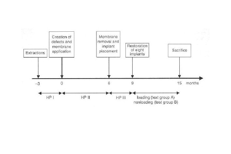
Material and Method 1. 5 foxhounds 2. 15 nonsubmerged titanium implants 3. Membrane protected regenerated bone 4. 8 implants : functional loading for 6 months 5. 7 implants : left unrestored Buser et al. JOMI 1995
 in the edentulous")
Creation of 3 rectangular, through and through defects (7× 7 mm) in the edentulous premolar area of the canine mandible. Placement of 3 e-PTFE membranes creating membrane protected defects filled with blood. Miniscrews for membrane stabilization are used.

Status following placement of two hollow-screw Implants. Note thin soft tissue layer covering parts of the bone surface. The buccal bone wall is intact in height at bone implants sites, but rather thin because of a concavity on the buccal aspect. The postoperative periapical radiograph confirms The placement of both implants in newly Regenerated bone.
. Both")
Periapical radiograph after seating of the implant restoration (3 months following implant placement). Both implants demonstrate no peri-implant radiolucency. Bone resorption of approximately 1 mm at the mesial implant (arrow). Periapical radiograph at completion of the Study (6 months of occlusal loading). Osseointegration is maintained radiographically. The crestal bone levels are more or less stable.

Low magnification of a mesiodistal section through two implants. The former defect sites Are delineated from the original bone by a More intense staining (arrows mark the borderline). The regenerated cortical bone is somewhat thinner, mostly the result of a Deepening in its periosteal surface. The middle portion of the implant is highly Surrounded by newly formed rather compact Bone. The apical part of the hollow-screw implant protrudes into the marrow cavity and Is supported by cancellous bone. The arrow indicates the junction between original and Regenerated bone. (Mag. × 3. 2)

Orofacial section through a loaded implant. Arrowheads mark the borderline at the bottom of the former defect site. Note the difference in thickness and height of the lingual (left) and buccal (right) bony wall bordering the implant. (Mag. × 2. 5)

The lingual wall supporting the implant consists of cortical bone. The borderline to the pre-existing bone is clearly visible (arrows), and the external (outer) surface of the implant is fully osseointegrated. (Mag. × 6. 3)

Compared to the lingual aspect, the buccal wall is much thinner and demonstrate a vertical resorption of approximately 20%. The overall bone quality, however, is the same as on the lingual aspect, and osseointegration is excellent. (Mag. × 6. 3)

At higher magnification, the intimate contact and the full congruency at the level of the bone-implant interface is evident. The fine microgap is a preparatory artifact. Recently formed secondary osteons are more intensely stained indicating ongoing remodeling, even in close to the titanium surface (arrows). Mag. × 25

Another section of the same implant demonstrates the direct contact between the microporous titanium surface and mature cortical bone. Mag. × 25

Example of an implant placed in an oblique, nonaxial direction. The buccal bone wall is well maintained in height, but clearly thinner than on the lingual aspect because of the nonaxial implant placement. Mag. × 2. 5

Another implant with nonaxial placement. The lingual bone wall is thick and fully maintained in height, whereas the buccal wall is clearly thinner and partially resorbed. The apical portion of the hollow-screw implant is supported by cancellous bone trabeculae that emanate from the endosteal surface of the cortex. (Mag. × 2. 5)

Detail review of the lingual portion. The bone structure consists of preexisting bone that is clearly demarcated (arrows) from the newly formed bone strut that contacts the implant. (Mag. × 16)

Detailed view of the buccal portion. The implant “apex” is again supported by a trabecular bone strut. Note the complete coverage of the osteophilic TPS surface by a thin bone layer (arrows), indicating the excellent osteophilic properties of this microporous titanium surface (Mag. × 16)
")
Fig 11. The four sites of control group A (membrane protection throughout 15 months) show pronounced bone atrophy underneath the membrane. In all specimens, the thin cortical layer is in direct contact with the membrane, whereas central areas demonstrate a rarefied cancellous architecture with sparse bone trabeculae. Mag. × 2
. Higher magnification of Fig 11(a). A direct contact of the cortical")
Fig 12 (a). Higher magnification of Fig 11(a). A direct contact of the cortical layer to the membrane has been established by ongoing modeling activities with bone apposition at the outer bone surface, whereas the thickness of the cortex was diminished by endosteal bone resorption during the 15 -month healing period (Mag. × 3. 2)
. Detailed view of the direct bone contact with the cellocclusive portion of")
Fig 12(b). Detailed view of the direct bone contact with the cellocclusive portion of the membrane (Mag. × 25)

The four sites of control group B (membrane removal at 6 months, no implant placement). The overall size of the regenerated area is reduced in height and width, most likely caused by resorption at the periosteal bone surface. However, the cortical layer is thicker and the cancellous bone density is higher when compared with control group A. Mag. × 2

Results 1. All 15 implants showed direct and intimate contact of the microporous titanium surface with bone. 2. The peri-implant bone exhibited all signs of viability with osteocytes and ongoing bone remodeling in close proximity to the implant surfaces. Buser et al. JOMI 1995

Results 3. Bone resorption was consistently observed in the crestal area mesial and distal to the barrier membranes during healing. In contrast, no bone resorption took place beneath the membrane as demonstrated by the radiographs. 4. This indirectly confirmed clinical observations in ridge augmentation procedures that e-PTFE membranes protect membrane-covered bone and applied autografts against resorption. Buser et al. JOMI 1995

Results 5. The observed resorption peripheral to the membrane was most likely caused by the fact that the subperiosteal cortical layer was deprived of its vascular supply when the mucoperiosteal flap was elevated. 6. Following readaptation of the flap, this avascular cortical bone was resorbed superficially which was apparent both clinically and radiographically at the end of the 6 -month healing period. Buser et al. JOMI 1995

Results 7. Accordingly, a certain resorption has to be expected following membrane removal, when the newly formed bone is exposed and left unprotected ( about 1. 0 -1. 5 mm). 8. The vascular supply for newly formed bone in a membrane-protected defect is primarily derived from the marrow cavity, since the overlying mucosa with the periosteum is blocked off by the membrane. Buser et al. JOMI 1995

Soft tissue layer underneath the removed membrane 1. The histologic study by Schenk et al. has shown that this soft tissue layer is periosteum-like and well vascularized. 2. Thus, it seems advantageous to leave this soft tissue layer in place when the membrane is removed. 3. Ongoing bone modeling activity with bone apposition towards the membrane. Schenk et al. JOMI 1994

More pronounced bone resorption of buccal side 1. The bone wall, in general, thinner buccally than lingually at time of implant placement. A thin bone wall is susceptible to resorption, since the blood supply from the marrow cavity can be compromised or even cut off by the placement of an implant. 2. Therefore, a certain overextension of the ridge width is necessary in a lateral ridge augmentation procedure to maintain the buccal bone wall in height and in sufficient thickness following implant placement. Buser et al. JOMI 1995

Advantages of staged approach GBR technique 1. The preparation of implant recipient sites following successful bone regeneration in a membrane-protected defect is a traumatic stimulus that will activate bone formation a second time by the release of growth factors and other bone-inducing factors. 2. This was confirmed in the present study, since the cortical layer was observed to be significantly thicker in all test sites, especially on the lingual aspects. Buser et al. JOMI 1995

Simultaneous approach vs Staged approach 1. Staged approach provides a larger bone surface available to contribute to new bone formation, since no implant is placed in the defect area. 2. With simultaneous approach, the implant reduces the exposed bone surface and its marrow space as a source of angiogenic and osteogenic cells. Buser et al. JOMI 1995

Simultaneous approach vs Staged approach 3. Primary stability of the implant is improved since the implant is placed when the alveolar ridge is already regenerated. 4. Furthermore, the staged approach offers advantages with respect to bone maturation, since new bone formation is activated twice by the local release of growth factors. Buser et al. JOMI 1995

BIC quality of Simultaneous approach vs Staged approach 1. It can be assumed that better bone apposition to the titanium surface is achieved with a staged approach, since the “travel distance” for osteogenic elements to the implant surface is much shorter for establishing direct bone-to-implant contacts when compared with a simultaneous approach. 2. In a histologic study of canine mandible utilizing a simultaneous application of e-PTFE membranes and different bone filers to regenerate buccal dehiscence-type defects, only sparse bone-to-implant contact could be observed. Buser et al. JOMI 1995

Conclusion 1. It can be concluded that bone regenerated in membrane-protected defects responds to implant placement like non-regenerated bone, and that this bone capable of bearing and sustaining functional load. Buser et al. JOMI 1995

Conclusion 2. It appears that functional load of restored implants did not influence bone remodeling patterns in the present study model. It might be that the applied load was not sufficient, or that the loading period of 6 months was not long enough to result in observable differences. Buser et al. JOMI 1995

Conclusion 3. Generally thinner buccal bone wall most likely caused by a partial membrane collapse. 4. Oblique, nonaxial implant insertion resulting in a thin buccal bone wall and potential vascular compromise of that bone at time of implant placement. Buser et al. JOMI 1995

Conclusion 5. Control sites with no implant placement exhibited bone atrophy with a rarefied bone structure in the membrane-protected defect characterized by a thin cortical layer and sparse bone trabeculae. It can be concluded that implant placement was able to activate bone maturation and remodeling in test sites, since the preparation of the implant recipient sites represents an activating stimulus. Buser et al. JOMI 1995

Successful bone formation at immediate transmucosal implants : a clinical report Christoph H. F. Hämmerle, Urs Brägger, Bruno Schmid, Niklaus P. Lang Int. J. Oral Maxillofac. Implants , 1998 ; 13 : 522 -530

Material and Method 1. ITI dental implant 2. GTAM oval-4 or oval-6 3. Reentry surgery : 5 months following implantation Hämmerle et al. JOMI 1998
 61 Region Implant type * Implant length")
Patient no 1 Gender F Age (y) 61 Region Implant type * Implant length (mm) Membrane type** Fracture 15 HC 10 GTAM-4 Periodontitis 16 HC 10 GTAM-4 Reason for tooth extraction 2 F 57 Fracture 14 HC 10 GTAM-4 3 F 48 Caries 12 HC 10 GTAM-6 4 M 38 Fracture 11 HC 10 GTAM-4 5 F 49 Fracture 44 HC 10 GTAM-4 6 M 47 Periodontitis 14 HS 8 GTAM-4 7 M 47 Periodontitis 46 HS 10 GTAM-6 8 F 25 Periapical lesion 24 HC 12 GTAM-4 9 M 55 Fracture 22 HC 10 GTAM-4 10 M 60 Fracture 22 HC 12 GTAM-4 Complication during regeneration infection Hämmerle et al. JOMI 1998

Conclusion 1. GBR may be used successfully to generate bone into defects around transmucosal implants placed into fresh extraction sockets. 2. Based on the results of the present study, implants placed in a transmucosal position per se did not impair the successful outcome of the bone regeneration process. Hämmerle et al. JOMI 1998

Conclusion 3. Infection control appears to be the key factor for an optimal treatment outcome, rather than merely the choice of submerged or transmucosal implant position. 4. It may anticipated that the bone located next to the smooth surface will be resorbed during the first year of implant function. Hämmerle et al. JOMI 1998
- Slides: 39