Oscillators Presented by Dr SAROAJ ADAK Professor DEPARTMENT

Oscillators Presented by Dr. SAROAJ ADAK Professor DEPARTMENT OF ELECTRONICS AND COMMUNICATION ENGINEERING VISAKHA INSTITUTE OF ENGINEERING & TECHNOLOGY

Introduction u Oscillator is an electronic circuit that generates a periodic waveform on its output without an external signal source. It is used to convert dc to ac. u Oscillators are circuits that produce a continuous signal of some type without the need of an input. u These signals serve a variety of purposes. u Communications systems, digital systems (including computers), and test equipment make use of oscillators

Oscillators Oscillation: an effect that repeatedly and regularly fluctuates about the mean value Oscillator: circuit that produces oscillation Characteristics: wave-shape, frequency, amplitude, distortion, stability Ref: 06103104 HKN 3 EE 3110 Oscillator

Application of Oscillators u. Oscillators are used to generate signals, e. g. n n Used as a local oscillator to transform the RF signals to IF signals in a receiver; Used to generate RF carrier in a transmitter Used to generate clocks in digital systems; Used as sweep circuits in TV sets and CRO. Ref: 06103104 HKN 4 EE 3110 Oscillator

Oscillators l l Oscillators are circuits that generate periodic signals An oscillator converts DC power from the power supply into AC signal power spontaneously - without the need for an AC input source Figure 9. 67 Repetitive ramp waveform.

Introduction u An oscillator is a circuit that produces a repetitive signal from a dc voltage. u The feedback oscillator relies on a positive feedback of the output to maintain the oscillations. u The relaxation oscillator makes use of an RC timing circuit to generate a nonsinusoidal signal such as square wave Sine wave Square wave Sawtooth wave

Types of oscillators 1. RC oscillators n n Wien Bridge Phase-Shift 2. LC oscillators n n n Hartley Colpitts Crystal 3. Unijunction / relaxation oscillators

Linear Oscillators Figure 9. 68 A linear oscillator is formed by connecting an amplifier and a feedback network in a loop.

Integrant of Linear Oscillators For sinusoidal input is connected “Linear” because the output is approximately sinusoidal A linear oscillator contains: - a frequency selection feedback network - an amplifier to maintain the loop gain at unity Ref: 06103104 HKN 9 EE 3110 Oscillator

Basic Linear Oscillator and If Vs = 0, the only way that Vo can be nonzero is that loop gain A =1 which implies that (Barkhausen Criterion) Ref: 06103104 HKN 10 EE 3110 Oscillator

Basic principles for oscillation u An oscillator is an amplifier with positive feedback.

Basic principles for oscillation u The closed loop gain is:

Basic principles for oscillation u In general A and are functions of frequency and thus may be written as; is known as loop gain

Basic principles for oscillation u Writing u Replacing s with j u and the loop gain becomes;

Basic principles for oscillation u At a specific frequency f 0 u At this frequency, the closed loop gain; will be infinite, i. e. the circuit will have finite output for zero input signal - oscillation

Basic principles for oscillation u Thus, the condition for sinusoidal oscillation of frequency f 0 is; u This is known as Barkhausen criterion. u The frequency of oscillation is solely determined by the phase characteristic of the feedback loop – the loop oscillates at the frequency for which the phase is zero.

Barkhausen Criterion – another way Figure 9. 69 Linear oscillator with external signal Xin injected.

Barkhausen Criterion

How does the oscillation get started? u. Noise signals and the transients associated with the circuit turning on provide the initial source signal that initiate the oscillation

Practical Design Considerations u Usually, oscillators are designed so that the loop gain magnitude is slightly higher than unity at the desired frequency of oscillation u This is done because if we designed for unity loop gain magnitude a slight reduction in gain would result in oscillations that die to zero u The drawback is that the oscillation will be slightly distorted (the higher gain results in oscillation that grows up to the point that will be clipped)

Basic principles for oscillation u The feedback oscillator is widely used for generation of sine wave signals. u. The positive (in phase) feedback arrangement maintains the oscillations. u. The feedback gain must be kept to unity to keep the output from distorting.

Basic principles for oscillation

Design Criteria for Oscillators 1. The magnitude of the loop gain must be unity or slightly larger – Barkhaussen criterion 2. Total phase shift, of the loop gain mus t be Nx 360° where N=0, 1, 2, …

RC Oscillators u RC feedback oscillators are generally limited to frequencies of 1 MHz or less. u The types of RC oscillators that we will discuss are the Wien-bridge and the phase-shift


Wien-bridge Oscillator u It is a low frequency oscillator which ranges from a few k. Hz to 1 MHz.

Another way Figure 9. 70 Typical linear oscillator.

Wien-bridge Oscillator u The loop gain for the oscillator is; u where; u and;

Wien-bridge Oscillator u Hence; u Substituting for s; u For oscillation frequency f 0
 must be real")
Wien-bridge Oscillator u Since at the frequency of oscillation, T(j ) must be real (for zero phase condition), the imaginary component must be zero; u which gives us – [how? ! – do it now]
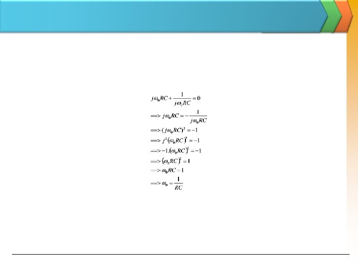
, u the")
Wien-bridge Oscillator u From the previous eq. (for oscillation frequency f 0), u the magnitude condition is; To ensure oscillation, the ratio R 2/R 1 must be slightly greater than 2.

Wien-bridge Oscillator u With the ratio; u then; K = 3 ensures the loop gain of unity – oscillation n n K > 3 : growing oscillations K < 3 : decreasing oscillations

Wien-Bridge Oscillator – another way Wien-bridge oscillator.

Wien-Bridge oscillator output Figure 9. 75 Example of output voltage of the oscillator.

Wien Bridge Oscillator Let and Frequency Selection Network Therefore, the feedback factor, Ref: 06103104 HKN 36 EE 3110 Oscillator

can be rewritten as: For Barkhausen Criterion, imaginary part = 0, i. e. , Supposing, R 1=R 2=R and XC 1= XC 2=XC, Ref: 06103104 HKN 37 EE 3110 Oscillator

Example By setting , we get Imaginary part = 0 and Due to Barkhausen Criterion, Loop gain Av =1 where Av : Gain of the amplifier Wien Bridge Oscillator Therefore, Ref: 06103104 HKN 38 EE 3110 Oscillator

Phase-Shift Oscillator u The phase shift oscillator utilizes three RC circuits to provide 180º phase shift that when coupled with the 180º of the op-amp itself provides the necessary feedback to sustain oscillations. u The gain must be at least 29 to maintain the oscillations. u The frequency of resonance for the this type is similar to any RC circuit oscillator:

Phase-Shift Oscillator vi C C v 1 R C v 2 v 1 R R v 3 R 2 vo
: u Set s=jw")
Phase-Shift Oscillator u Loop gain, T(s): u Set s=jw
=1, real component must be zero since the")
Phase-Shift Oscillator u To satisfy condition T(jwo)=1, real component must be zero since the numerator is purely imaginary. u the oscillation frequency: u Apply wo in equation: u. To satisfy condition T(jwo)=1 The gain greater than 8, the circuit will spontaneously begin oscillating & sustain oscillations

Phase-Shift Oscillator The gain must be at least 29 to maintain the oscillations

LC Oscillators u Use transistors and LC tuned circuits or crystals in their feedback network. u For hundreds of k. Hz to hundreds of MHz frequency range. u Examine Colpitts, Hartley and crystal oscillator.

Colpitts Oscillator u The Colpitts oscillator is a type of oscillator that uses an LC circuit in the feed-back loop. u The feedback network is made up of a pair of tapped capacitors (C 1 and C 2) and an inductor L to produce a feedback necessary for oscillations. u The output voltage is developed across C 1. u The feedback voltage is developed across C 2.
 u voltage divider")
Colpitts Oscillator u KCL at the output node: - Eq (1) u voltage divider produces: - Eq (2) u substitute eq(2) into eq(1):

Colpitts Oscillator u Assume that oscillation has started, then Vo≠ 0 u Let s=jω u both real & imaginary component must be zero n Imaginary component: - Eq (3)

Colpitts Oscillator u both real & imaginary component must be zero n Imaginary component: - Eq (4) u Combining Eq(3) and Eq(4): u to initiate oscillations spontaneously:

Hartley Oscillator u The Hartley oscillator is almost identical to the Colpitts oscillator. u The primary difference is that the feedback network of the Hartley oscillator uses tapped inductors (L 1 and L 2) and a single capacitor C. C

Hartley Oscillator u the analysis of Hartley oscillator is identical to that Colpitts oscillator. u the frequency of oscillation:

Crystal Oscillator u Most communications and digital applications require the use of oscillators with extremely stable output Crystal oscillators are invented to overcome the output fluctuation experienced by conventional oscillators. u Crystals used in electronic applications consist of a quartz wafer held between two metal plates and housed in a a package as shown in Fig. 9 (a) and (b).

Crystal Oscillator u Piezoelectric Effect n n n The quartz crystal is made of silicon oxide (Si. O 2) and exhibits a property called the piezoelectric When a changing an alternating voltage is applied across the crystal, it vibrates at the frequency of the applied voltage. In the other word, the frequency of the applied ac voltage is equal to the natural resonant frequency of the crystal. The thinner the crystal, higher its frequency of vibration. This phenomenon is called piezoelectric effect.

Crystal Oscillator u Characteristic of Quartz Crystal n n n The crystal can have two resonant frequencies; One is the series resonance frequency f 1 which occurs when XL = XC. At this frequency, crystal offers a very low impedance to the external circuit where Z = R. The other is the parallel resonance (or antiresonance) frequency f 2 which occurs when reactance of the series leg equals the reactance of CM. At this frequency, crystal offers a very high impedance to the external circuit R L C CM

Crystal Oscillator u The crystal is connected as a series element in the feedback path from collector to the base so that it is excited in the series-resonance mode BJT FET

Crystal Oscillator u Since, in series resonance, crystal impedance is the smallest that causes the crystal provides the largest positive feedback. u Resistors R 1, R 2, and RE provide a voltage-divider stabilized dc bias circuit. Capacitor CE provides ac bypass of the emitter resistor, RE to avoid degeneration. u The RFC coil provides dc collector load and also prevents any ac signal from entering the dc supply. u The coupling capacitor CC has negligible reactance at circuit operating frequency but blocks any dc flow between collector and base. u The oscillation frequency equals the series-resonance frequency of the crystal and is given by:

Unijunction Oscillator u The unijunction transistor can be used in what is called a relaxation oscillator as shown by basic circuit as follow. u The unijunction oscillator provides a pulse signal suitable for digital-circuit applications. u Resistor RT and capacitor CT are the timing components that set the circuit oscillating rate UJT

Unijunction Oscillator u Sawtooth wave appears at the emitter of the transistor. u. This wave shows the gradual increase of capacitor voltage

Unijunction Oscillator u The oscillating frequency is calculated as follows: u where, η = the unijunction transistor intrinsic standoff ratio u Typically, a unijunction transistor has a stand-off ratio from 0. 4 to 0. 6
- Slides: 58