Orthographic Projection Orthographic Projection Important terms Horizontal Plane


 • Horizontal Plane • A plane parallel to the floor")
 • Vertical plane One plane conveniently selected out of the")
 • Auxiliary vertical plane A plane perpendicular to horizontal")


 is needed to fulfill the size description. Height")


- Slides: 35
Orthographic Projection
Orthographic Projection – Important terms Horizontal Plane A plane parallel to the floor is known as horizontal plane. Orthographic projection of an object on horizontal plane is known as top view (plan). Vertical plane One plane conveniently selected out of the planes perpendicular to horizontal plane is known as vertical plane. It is known as front view (elevation). Auxiliary vertical plane A plane perpendicular to both horizontal plane and vertical plane both is known as auxiliary vertical plane. Orthographic projection on A. V. P. is known as end view or side view.
• Projection If straight lines are drawn from various points on the contour of an object to meet a plane, object is said to projected at that plane the figure formed by joining in correct sequence the points at which the lines meet the plane is called a projection of the object. • Projectors The lines from the object to the plane are called as the projectors • Plane of projection The plane on which the projectors meet is known as the plane of projection • Orthographic projection When the projectors are parallel to each other and also perpendicular to the projection plane, the projection is called orthographic projection.
Orthographic Projection (Top View) • Horizontal Plane • A plane parallel to the floor is known as horizontal plane. Orthographic projection of an object on horizontal plane is known as top view (plan).
Orthographic Projection (Front View) • Vertical plane One plane conveniently selected out of the planes perpendicular to horizontal plane is known as vertical plane. It is known as front view (elevation).
Orthographic Projection (Right Side View) • Auxiliary vertical plane A plane perpendicular to horizontal plane and vertical plane both is known as auxiliary vertical plane. Orthographic projection on A. V. P. is known as end view or side view.
Conti……. • Parallel edges of the object are shown by parallel lines. • Right angle remains as it is. • Semi circle also remains as such. • Each view show only two dimensions of the object.
Difference between First angle projection and Third angle projection No. First angle projection 1 The object is kept in the first quadrant. Third angle projection The object is assumed to be kept in the third quadrant. 2 The object lies between the observer and the plane of projection. The plane of projection lies between the observer and the object. 3 The plane of projection is assumed to be non-transparent. assumed to be transparent. 4 Plan comes below the elevation Plan comes above the elevation and left side view is drawn to the right of elevation. left side of the elevation 5 This method of projection is now recommended in India This method is used in USA and other countries.
Symbols for 1 st & 3 rd Angle Projection
MULTIVIEW PROJECTION Width Depth Adjacent view(s) is needed to fulfill the size description. Height Each view will represented only two dimension. Depth Three principle dimensions of an object … Width Depth
TO OBTAIN MULTIVIEW REVOLVE THE OBJECT Top view Front view Right side view
OBSERVER MOVE AROUND Top view Front view Right side view
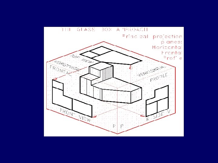
THE GLASS BOX CONCEPT Rear view Left side view Bottom view
Depth History Width Height
PROJECTION OF OBJECT The views are obtained by projecting all object features to the picture plane.
PROJECTION OF OBJECT s s s
PROJECTION OF OBJECT
OBJECT FEATURES Edges are lines that represent the boundary between two faces. Corners Represent the intersection of two or more edges. Edge Corner Edge No corner No edge No corner
OBJECT FEATURES Surfaces areas that are bounded by edges or limiting element. Limiting element is a line that represents the last visible part of the curve surface. Surface Limit
Orthographic Projection • Orthographic drawings represent three dimensional objects in three separate views arranged in a standard manner.
Converting to Orthographic
Orthographic Views
Orthographic Projection a system of drawing views of an object using perpendicular projectors from the object to a plane of projection
Revolving an Object to Produce the other Views
The Six Basic Views
The Standard Arrangement of Views TOP LEFT FRONT RIGHT BOTTOM REAR To make it possible for someone to interpret the drawing.
Orthographic Projection
Opening the Box
Final views for third angle projection method
Object for exercise • Complete three orthographic views of the object. • Include visible, hidden, and center lines where appropriate.
Solution
Solution