Orbital Mechanics II Transfers Rendezvous Patched Conics and

Orbital Mechanics II: Transfers, Rendezvous, Patched Conics, and Perturbations Dr. Andrew Ketsdever Lesson 3 MAE 5595

Orbital Transfers • Hohmann Transfer – Efficient means of increasing/decreasing orbit size – Doesn’t truly exist – Assumptions • • Initial and final orbits in the same plane Co-apsidal orbits (Major axes are aligned) ΔV is instantaneous ΔV is tangential to initial and final orbits (velocity changes magnitude but not direction)

Hohmann Transfer

Hohmann Transfer

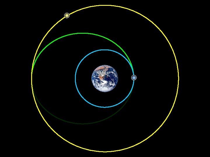
Conceptual Walkthrough alt 1 = 300 km alt 2 = 1000 km 2 Slides Courtesy of Major David French, USAFA/DFAS V 1 ΔV 1

2 Vt 1

ΔV 2 Vt 2 2

V 2 2

Time of Flight 2

Hohmann Transfer

Orbital Transfers • One Tangent Burn Transfer – First burn is tangent to the initial orbit – Second burn is at the final orbit • Transfer orbit intersects final orbit • An infinite number of transfer orbits exist • Transfer orbit may be elliptical, parabolic or hyperbolic – Depends on transfer orbit energy – Depends on transfer time scale

One-Tangent Burn

One-Tangent Burn

Spiral Transfer Expect to multiply by as much as a factor of 2 for some missions

Orbital Transfer • Plane Changes – Simple • Only changes the inclination of the orbit, not its size – Combined • Combines the ΔV maneuver of a Hohmann (tangential) transfer with the ΔV maneuver for a plane change • Efficient means to change orbit size and inclination

Plane Changes • Simple – • Combined –

Rendezvous • Co-Orbital Rendezvous – Interceptor and Target initially in the same orbit with different true anomalies • Co-Planar Rendezvous – Interceptor and Target initially in different orbits with the same orbital plane (inclination and RAAN)

Co-Orbital Rendezvous

Co-Orbital Rendezvous Target Leading

Co-Orbital Rendezvous Target Leading

Co-Orbital Rendezvous Target Leading 3 step process for determining phasing orbit size

Co-Orbital Rendezvous Target Leading ωTGT 1

Co-Orbital Rendezvous Target Leading ωTGT Φtravel 2

Co-Orbital Rendezvous Target Leading ωTGT Φtravel 3

Co-Orbital Rendezvous Target Trailing

Co-Orbital Rendezvous Target Trailing

Co-Orbital Rendezvous Target Trailing ωTGT Φtravel

Co-Planar Rendezvous

Coplanar Rendezvous
")
2 5 step process for determining wait time (WT)

1 ωTGT ωINT 2

2 TOF 2

3 ωTGT TOF αlead ωINT 2

4 ωTGT Φfinal αlead ωINT 2

5 ωTGT Φfinal αlead ωINT 2 Φinitial
, we")
Interplanetary Travel • In our two-body universe (based on the restricted, two-body EOM), we can not account for the influence of other external forces – In reality we can account for many body problems, but for our purposes of simplicity we will stick to two-body motion in the presence of gravity – Need a method to insure that only two-bodies are acting during a particular phase of the spacecraft’s motion • Spacecraft – Earth (from launch out to the Earth’s SOI) • Spacecraft – Sun (From Earth SOI through to the Target SOI) • Spacecraft – Planet (From Target Planet SOI to orbit or surface)
")
Patched Conic Approximation • Spacecraft – Earth – Circular or Elliptical low-Earth orbit (Parking) – Hyperbolic escape – Geo-centric, equatorial coordinate system • Spacecraft – Sun – Elliptical Transfer Orbit – Helio-centric, ecliptic coordinate system • Spacecraft – Target – Hyperbolic arrival – Circular or Elliptical orbit – Target-centric, equatorial coordinate system

Patched Conic Approximation Geo: Hyperbolic escape Helio: Elliptical transfer Targeto: Hyperbolic arrival

Orbital Perturbations • Several factors cause perturbations to a spacecraft’s attitude and/or orbit – Drag – Earth’s oblateness – Actuators – 3 rd bodies – Gravity gradient – Magnetic fields – Solar pressure

Orbital Drag • Orbital drag is an issue in low-Earth orbit – Removes energy from the s/c orbit (lowers) – Orbital decay due to drag depends on several factors • Spacecraft design • Orbital velocity • Atmospheric density – Altitude, Latitude – Solar activity

3 rd Bodies • Geosynchronous Equatorial Orbits are influenced by the Sun and Moon

3 rd Bodies • Right ascension of the ascending node: i = orbit inclination n = number of orbit revs per day • Argument of perigee

Gravity Gradient, Magnetic Field, Solar Pressure I = s/c moment of inertia about axis R = s/c distance from center of Earth = angle between Z axis and local vertical D = s/c electric field strength (Am 2) B = local magnetic field strength (T); varies with R-3 = 1367 W/m 2 at Earth’s orbit c = speed of light r= reflectivity = angle of incidence

Varying Disturbance Torques NOTE: The magnitudes of the torques is dependent on the spacecraft design. Torque (au) Drag Gravity Solar Press. Magnetic LEO GEO Orbital Altitude (au)

Actuators • Passive – Gravity Gradient Booms – Electrodynamic Tethers • Active – Magnetic Torque Rods – Thrusters

Oblate Earth • The Earth is not a perfect sphere with the mass at the center (point mass) – In fact, the Earth has a bulge at the equator and a flattening at the poles – Major assumption of the restricted, two-body EOM • The J 2 effects – RAAN – Argument of perigee • Magnitude of the effect is governed by – Orbital altitude – Orbital eccentricity – Orbital inclination Earth's second-degree zonal spherical harmonic coefficient

J 2 Effects

Sun Synchronous Orbit • Select appropriate inclination of orbit to achieve a nodal regression rate of ~1º/day (Orbit 360º in 365 days)

J 2 Effects

Molniya Orbit • Select orbit inclination so that the argument of perigee regression rate is essentially zero – Allows perigee to remain in the hemisphere of choice – Allows apogee to remain in the hemisphere of choice • VIDEO

J 2 Increasing? J 2 Initial decrease thought to be from a mantle rebound from melted ice since the last Ice Age Recent increase can only be caused by a significant movement of mass somewhere in the Earth C. Cox and B. F. Chao, "Detection of large-scale mass redistribution in the terrestrial system since 1998, " Science, vol 297, pp 831, 2 August 2002.
- Slides: 52