
Optoelectronics dr Konstanty Marszaek Applications of thin film

- Slides: 13
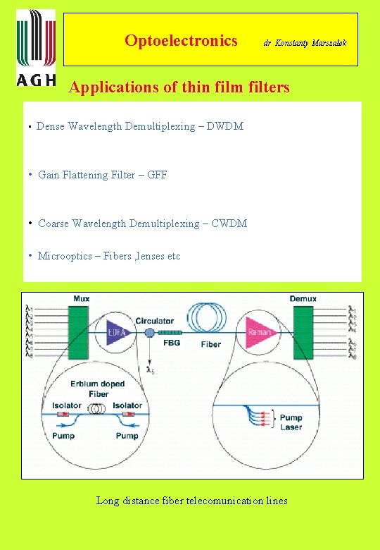
Optoelectronics dr Konstanty Marszałek Applications of thin film filters • Dense Wavelength Demultiplexing – DWDM • Gain Flattening Filter – GFF • Coarse Wavelength Demultiplexing – CWDM • Microoptics – Fibers , lenses etc Long distance fiber telecomunication lines
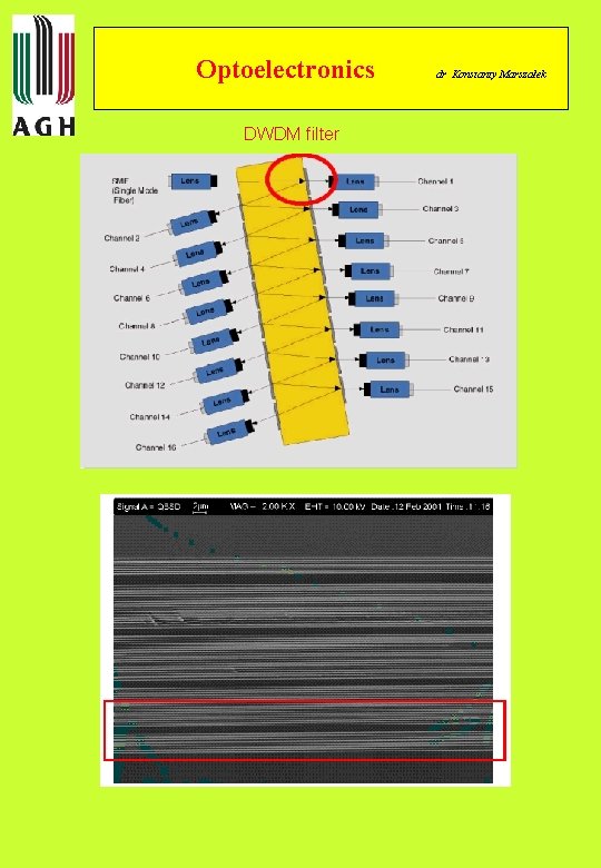
Optoelectronics DWDM filter dr Konstanty Marszałek
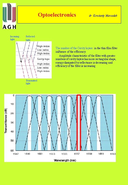
Optoelectronics Incoming light dr Konstanty Marszałek Reflected light The number of the Cavity layesr in the thin film filter inlfuence of the efficiency. Amplitude characteristic of the filter with greater numbers of cavity layers has more rectangular shape, energy dissipated by reflectance is decreasing and efficiency of the filter is increasing Transmitted light
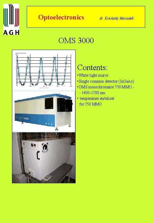
Optoelectronics dr Konstanty Marszałek OMS 3000 Contents: • White light source • Single common detector (In. Ga. As) • OMS monochromator 750 MMO - 1400 -1700 nm • temperature stabiliser for 750 MMO
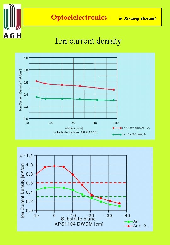
Optoelelectronics dr Konstanty Marszałek Ion current density
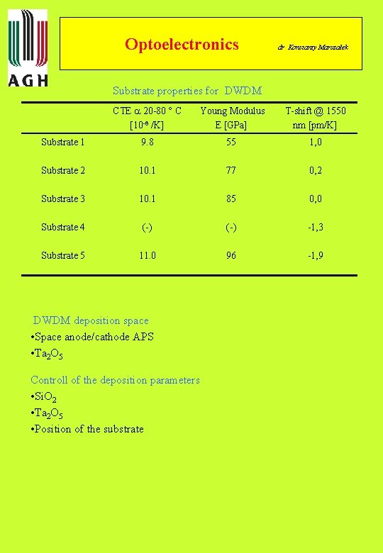
Optoelectronics dr Konstanty Marszałek Substrate properties for DWDM CTE 20 -80 C [10 -6 /K] Young Modulus E [GPa] T-shift @ 1550 nm [pm/K] Substrate 1 9. 8 55 1, 0 Substrate 2 10. 1 77 0, 2 Substrate 3 10. 1 85 0, 0 Substrate 4 (-) -1, 3 Substrate 5 11. 0 96 -1, 9 DWDM deposition space • Space anode/cathode APS • Ta 2 O 5 Controll of the deposition parameters • Si. O 2 • Ta 2 O 5 • Position of the substrate
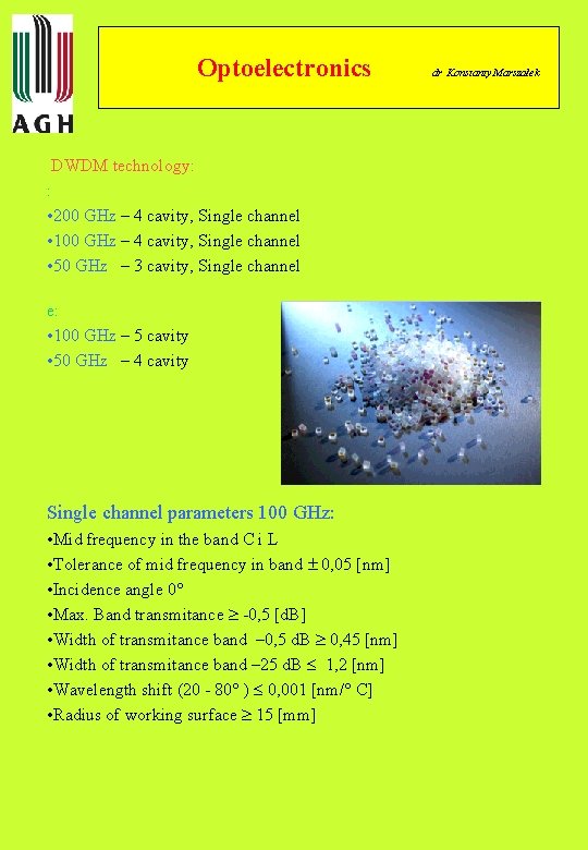
Optoelectronics DWDM technology: : • 200 GHz – 4 cavity, Single channel • 100 GHz – 4 cavity, Single channel • 50 GHz – 3 cavity, Single channel e: • 100 GHz – 5 cavity • 50 GHz – 4 cavity Single channel parameters 100 GHz: • Mid frequency in the band C i L • Tolerance of mid frequency in band 0, 05 [nm] • Incidence angle 0 • Max. Band transmitance -0, 5 [d. B] • Width of transmitance band – 0, 5 d. B 0, 45 [nm] • Width of transmitance band – 25 d. B 1, 2 [nm] • Wavelength shift (20 - 80 ) 0, 001 [nm/ C] • Radius of working surface 15 [mm] dr Konstanty Marszałek
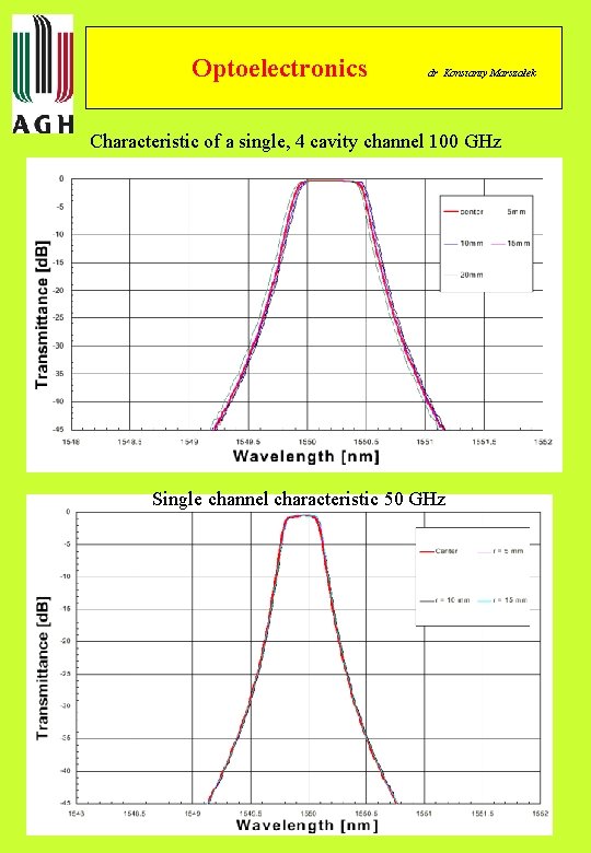
Optoelectronics dr Konstanty Marszałek Characteristic of a single, 4 cavity channel 100 GHz Single channel characteristic 50 GHz
Optoelectronics dr Konstanty Marszałek Mapping station for investigations of thin films filter parameters
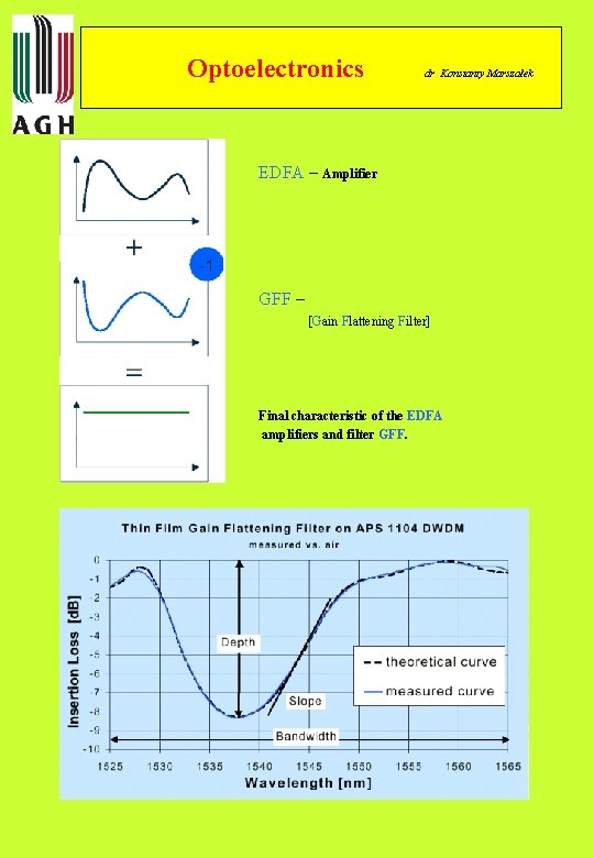
Optoelectronics dr Konstanty Marszałek EDFA – Amplifier GFF – [Gain Flattening Filter] Final characteristic of the EDFA amplifiers and filter GFF.
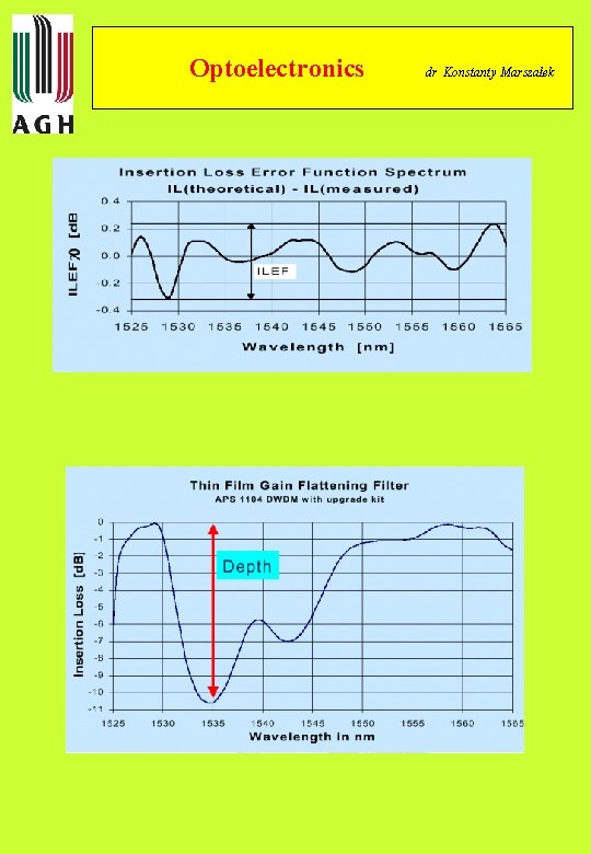
Optoelectronics dr Konstanty Marszałek
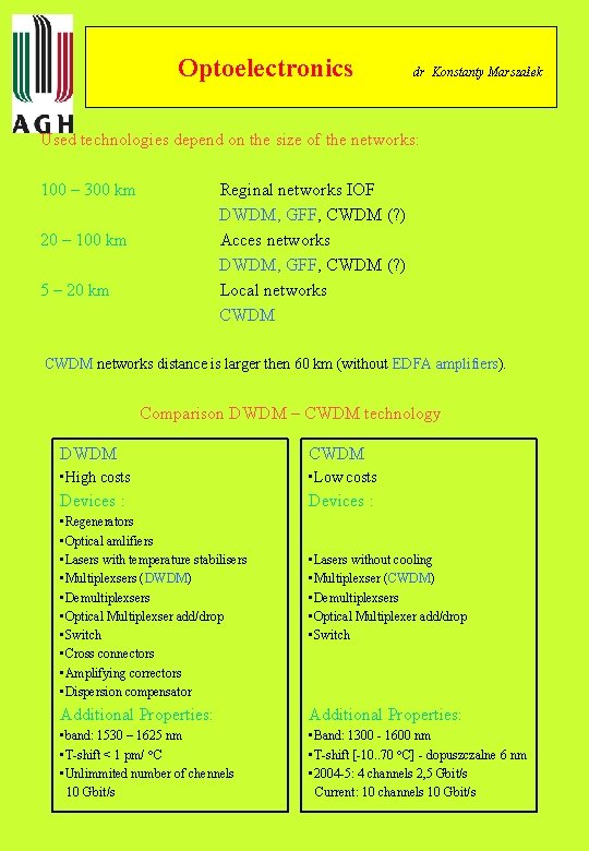
Optoelectronics dr Konstanty Marszałek Used technologies depend on the size of the networks: 100 – 300 km Reginal networks IOF DWDM, GFF, CWDM (? ) Acces networks DWDM, GFF, CWDM (? ) Local networks CWDM 20 – 100 km 5 – 20 km CWDM networks distance is larger then 60 km (without EDFA amplifiers). Comparison DWDM – CWDM technology DWDM CWDM • High costs • Low costs Devices : • Regenerators • Optical amlifiers • Lasers with temperature stabilisers • Multiplexsers (DWDM) • Demultiplexsers • Optical Multiplexser add/drop • Switch • Cross connectors • Amplifying correctors • Dispersion compensator • Lasers without cooling • Multiplexser (CWDM) • Demultiplexsers • Optical Multiplexer add/drop • Switch Additional Properties: • band: 1530 – 1625 nm • T-shift < 1 pm/ C • Unlimmited number of chennels 10 Gbit/s • Band: 1300 - 1600 nm • T-shift [-10. . 70 C] - dopuszczalne 6 nm • 2004 -5: 4 channels 2, 5 Gbit/s Current: 10 channels 10 Gbit/s
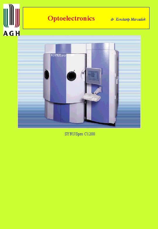
Optoelectronics SYRUSpro C 1200 dr Konstanty Marszałek