
Optoelectronics 9142021 Silja Kinnunen and Antti Asikainen The
- Slides: 21
Optoelectronics 9/14/2021 Silja Kinnunen and Antti Asikainen
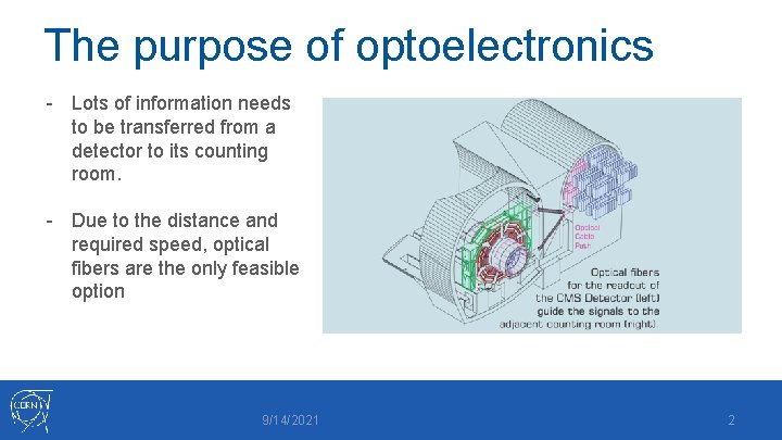
The purpose of optoelectronics - Lots of information needs to be transferred from a detector to its counting room. - Due to the distance and required speed, optical fibers are the only feasible option 9/14/2021 2
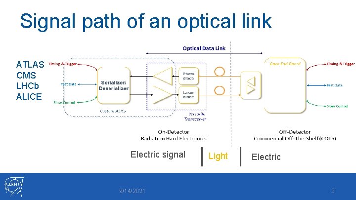
Signal path of an optical link ATLAS CMS LHCb ALICE Electric signal 9/14/2021 Light Electric 3
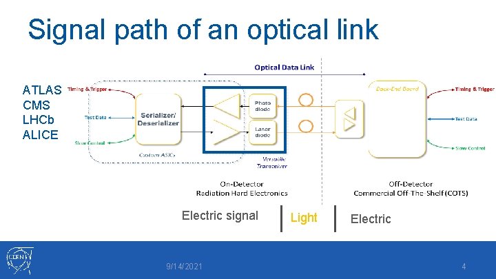
Signal path of an optical link ATLAS CMS LHCb ALICE Electric signal 9/14/2021 Light Electric 4
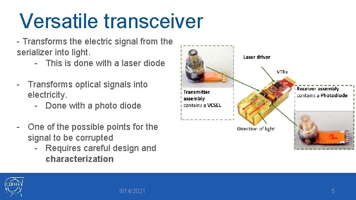
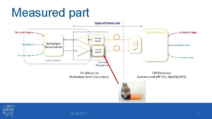
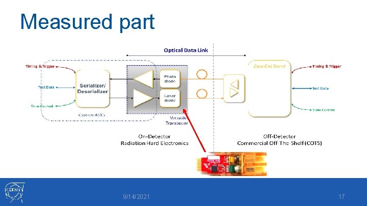
Versatile transceiver - Transforms the electric signal from the serializer into light. - This is done with a laser diode - Transforms optical signals into electricity. - Done with a photo diode - One of the possible points for the signal to be corrupted - Requires careful design and characterization 9/14/2021 5
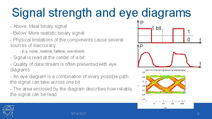
Signal strength and eye diagrams - Above: Ideal binary signal - Below: More realistic binary signal - Physical limitations of the components cause several sources of inaccuracy: P 1 bit 1 0 t P - E. g. noise, risetime, falltime, overshoots - Signal is read at the center of a bit - Quality of data stream is often presented with eye diagrams - An eye diagram is a combination of every possible path the signal can take across one bit - The area enclosed by the diagram describes how reliably the signal can be read 9/14/2021 t 6
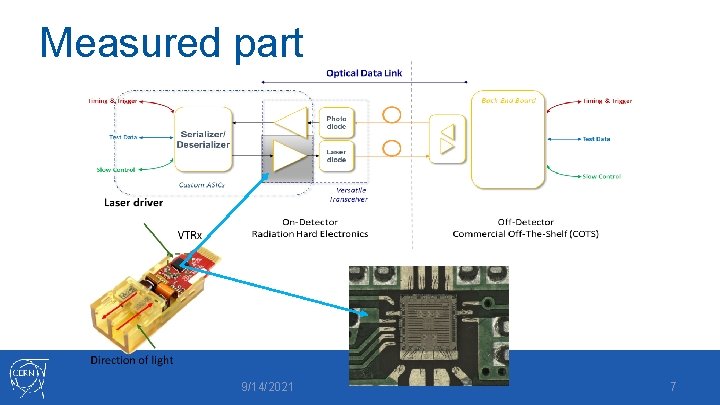
Measured part 9/14/2021 7
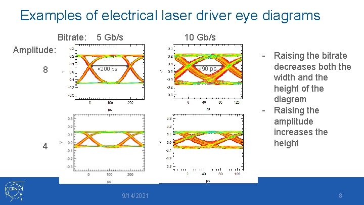
Examples of electrical laser driver eye diagrams Bitrate: 5 Gb/s 10 Gb/s Amplitude: 8 <90 ps <200 ps 4 9/14/2021 - Raising the bitrate decreases both the width and the height of the diagram - Raising the amplitude increases the height 8
Measured part 9/14/2021 9
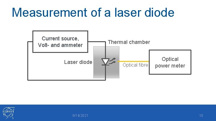
Measurement of a laser diode Current source, Volt- and ammeter Laser diode 9/14/2021 Thermal chamber Optical fibre Optical power meter 10
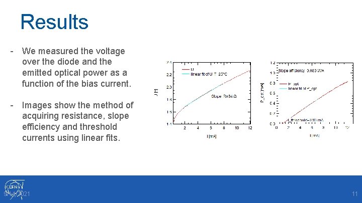
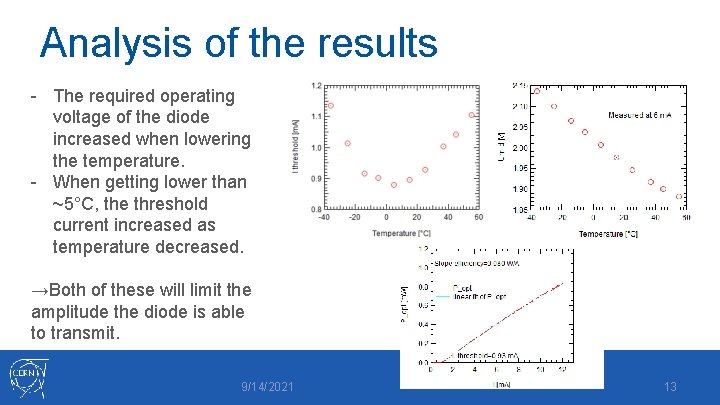
Results - We measured the voltage over the diode and the emitted optical power as a function of the bias current. - Images show the method of acquiring resistance, slope efficiency and threshold currents using linear fits. 9/14/2021 11
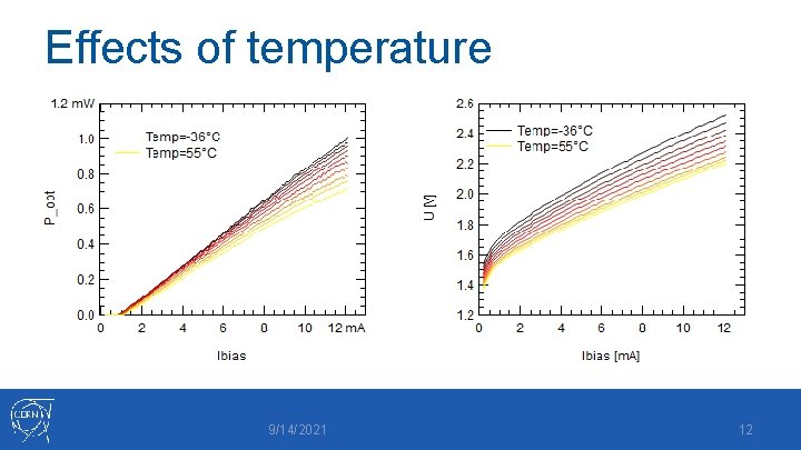
Effects of temperature 9/14/2021 12
Analysis of the results - The required operating voltage of the diode increased when lowering the temperature. - When getting lower than ~5°C, the threshold current increased as temperature decreased. →Both of these will limit the amplitude the diode is able to transmit. 9/14/2021 13
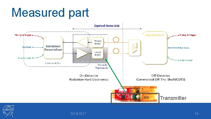
Measured part Transmitter 9/14/2021 14
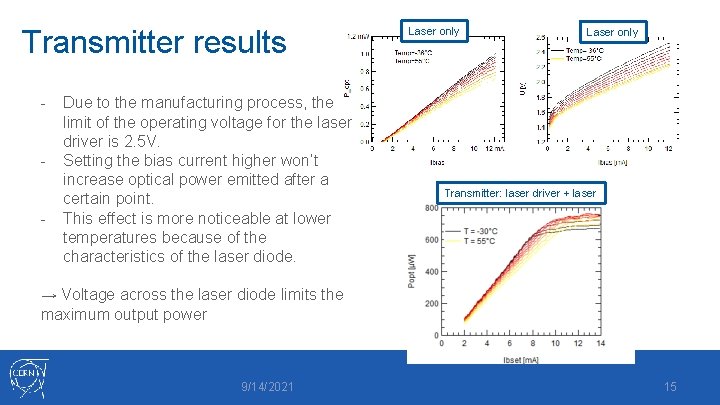
Transmitter results - Due to the manufacturing process, the limit of the operating voltage for the laser driver is 2. 5 V. Setting the bias current higher won’t increase optical power emitted after a certain point. This effect is more noticeable at lower temperatures because of the characteristics of the laser diode. Laser only Transmitter: laser driver + laser → Voltage across the laser diode limits the maximum output power 9/14/2021 15
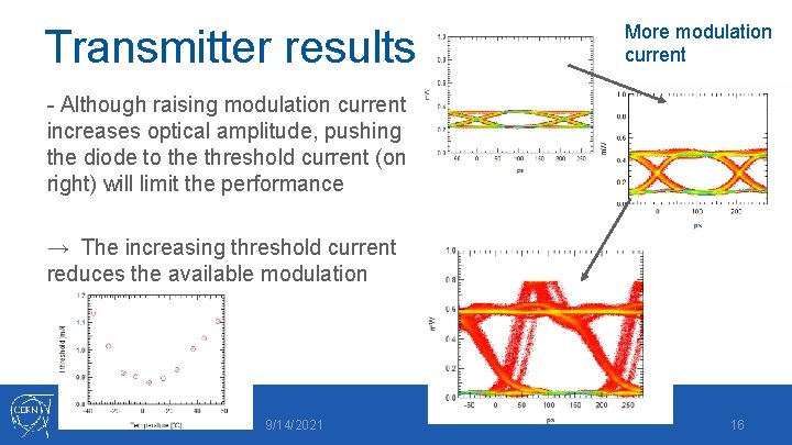
Transmitter results More modulation current - Although raising modulation current increases optical amplitude, pushing the diode to the threshold current (on right) will limit the performance → The increasing threshold current reduces the available modulation 9/14/2021 16
Measured part 9/14/2021 17
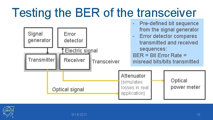
Testing the BER of the transceiver Signal generator Error detector Electric signal Transmitter Receiver Transceiver - Pre-defined bit sequence from the signal generator - Error detector compares transmitted and received sequences: BER = Bit Error Rate = misread bits/bits transmitted Attenuator Optical signal 9/14/2021 (simulates losses in real application) Optical power meter 18
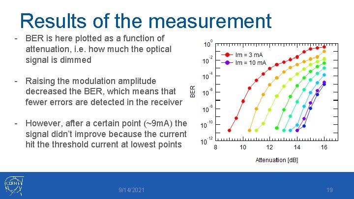
Results of the measurement - BER is here plotted as a function of attenuation, i. e. how much the optical signal is dimmed - Raising the modulation amplitude decreased the BER, which means that fewer errors are detected in the receiver - However, after a certain point (~9 m. A) the signal didn’t improve because the current hit the threshold current at lowest points 9/14/2021 19
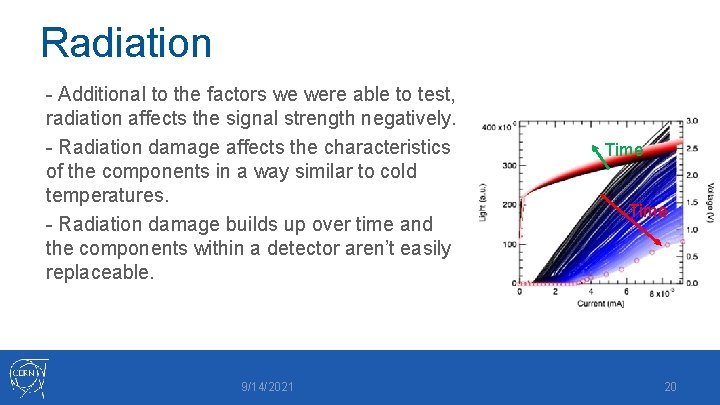
Radiation - Additional to the factors we were able to test, radiation affects the signal strength negatively. - Radiation damage affects the characteristics of the components in a way similar to cold temperatures. - Radiation damage builds up over time and the components within a detector aren’t easily replaceable. 9/14/2021 Time 20
Summary - Detector chamber’s unusual environment causes several different problems for optical data links. - However, optical fibre is currently the only data transferring method capable of meeting the requirements of the experiments. - With careful characterization and design, CERN has been able to overcome these problems. 9/14/2021 21