Optoelectric Transducers Contents Introduction Definition Basic principles Types

Opto-electric Transducers Contents • Introduction: Definition, Basic principles • Types: Photoemissive Cell, Photoconductive Cell, Photo-voltaic cell, Photodiode, Phototransistor • Applications: Digital encoding transducers

2 Optical Sensors: Fundamentals Interaction with medium Sensor works based on changes of these parameters (Intensity, frequency & phase)

Why optical sensors are emerging choice?
 Applications")
Optical Sensors (OFS) Applications
 Applications")
Optical Sensors (OFS) Applications
 Applications")
Optical Sensors (OFS) Applications

Optical Sensors: Photodetectors Photodetector sensors works on the principle of photoconductivity, where the target material changes its conductivity in the presence or absence of light. ØSensitive for a given spectral region (range of optical wavelengths) from ultra-violet to infrared. The absorption of light energises the electrons of the material, and hence the electrons start moving. The mobility of electrons produces one of the three effects. 1. The resistance of the material changes. 2. The output current of the semiconductor changes. Works based on changes of intensity 3. The output voltage of the semiconductor changes. Types and examples: • • • Active pixel sensors → smartphone cameras and web cams Charged-coupled devices (CCD) → digital cameras Light-dependent resistors (LDRs) → street lighting systems Photodiodes → room lighting-level control or in UV measurement Phototransistors → opto-isolators (healthcare equipment, to provide electrical isolation between the patient and equipment) Photomultipliers → spectrophotometers detectors, flow cytometers (a laser-based technology used for cell counting and sorting and biomarker detection) for blood analysis applications

8 Optical sensors: Photo-emissive cell ØCathode: Coated with a photoemissive material called Na, K, or cesium antimony. ØAnode: straight wire made of Ni or Pt ØWhen the radiation of light fall on cathode plates the electrons starts flowing from anode to cathode. Both the anode and the cathode are sealed in a closed, opaque evacuated tube. When the radiation of light fall on the sealed tube, the electrons starts emitting from the cathode and moves towards the anode. The anode is kept to the positive potential. Thus, the photoelectric current starts flowing through the anode. The magnitude of the current is directly proportional to the intensity of light passes through it. Ø Non-linearity between light intensity and current Ø Applications: in television, photometry, fire-alarm.

9 Optical sensors: Photoconductive cell Ø Converts the light energy into an electric current. Ø Semiconductor material like Cd. Se, Ge. Se, as a photo sensing element. Ø When the beam of light falls on the semiconductor material, their conductivity increases and the material works like a closed switch. LDR

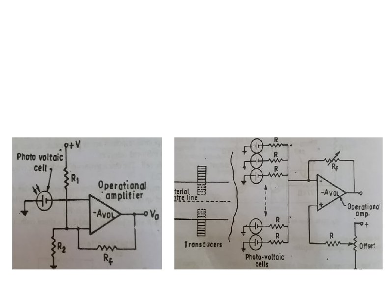
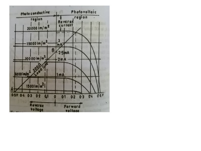
1 0 Optical sensors: Photovoltaic cell ØA type of active transducer. ØThe current starts flowing into the photovoltaic cell when the load is connected to it. ØSi and Se are used as a semiconductor material. ØWhen the semiconductor material absorbs light, the free electrons of the material starts moving. This phenomenon is known as the photovoltaic effect. ØThe movements of electrons develop the current in the cell, and the current is known as the photoelectric current.

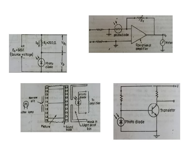
1 1 Optical sensors: Photodiode ØThe photodiode is a semiconductor material which converts the light into the current. ØIt’s basically a PN junction designed to operate in reverse bias ØThe electrons of the semiconductor material start moving when the photodiode absorbs the light energy. The response time of the photodiode is very less.
 ØNo active source, subject of interest radiates EM")
1 2 Optical sensors: Infrared (IR) ØNo active source, subject of interest radiates EM energy in the form of heat ØSensors acceptance angle important ØSource and detectors can be located on a same enclosure or separately opposite to each other Applications: Counters, proximity sensors, night vision camera and so on Adv: Low power requirements, relatively high immunity to noise, and do not require complex signal processing circuitry Disadv: need to be in line-of-sight of the object of interest, a relatively short detection range, and being subject to interference from environmental sources such as sunlight, fog, rain, and dust

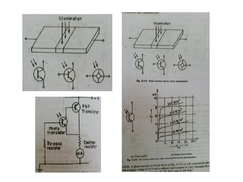
1 3 Optical sensors: Phototransistor Produces both the current and voltage. The base semiconductor material is enclosed in an opaque container in which the light easily reaches to the photosensitive element. The element absorbs light, and the current starts flowing from base to emitter of the device. This current is converted into the voltages.

Optical Sensors: Fiber Optic The most commonly used fiber-optic sensor types include: • Strain sensing: Mechanical strain changes the geometric properties of the fiber. • Temperature sensing: Strain in the fiber is caused by thermal expansion or contraction • Pressure sensing: Fiber-optic pressure sensors —intensity and interferometric. In intensity-sensing fiber-optic sensors, the magnitude of light intensity reflected from a thin diaphragm changes with applied pressure. Interferometric pressure sensors work on the principle that pressure changes introduce perturbations into the sensor, which generate path-length changes in a fiber. This in turn causes the light/dark bands of an interference pattern to shift. By measuring the shift of the wavelength spectrum, the pressure applied on it can be quantitatively obtained. • Humidity sensing: A broad range of principles have been applied to optical fiber-based humidity sensors, including (i) luminescent systems with fluorescent dyes that are humidity-sensitive (ii) refractive index changes due to absorption in a hygroscopic (moisture absorbing) fibe coating such as polyimide; and (iii) reflective thin film-coated fibers made from tin dioxide (Sn. O 2) and titanium dioxide (Ti. O 2), which change the refractive index, resulting in a shift in resonance frequency (Morendo-Bondi, et al. , 2004).

1 5 Interferometric sensors: Introduction Interferometry Light from a single coherent source is split into two beams that travel in different optical paths, which are then combined again to produce interference. This can be measured analyzed to detect the phase change (optical path lengths) caused by small displacements, refractive index changes and surface irregularities. In analytical science, interferometers are used to measure lengths and the shape of optical components with nanometer precision; they are the highest precision length measuring instruments existing. Types – 4 types 1. 2. 3. 4. Sagnac interferometer Mach–Zehnder interferometer Michelson interferometer Fabry–Perot interferometer Effect in image

Fiber Optic Sensors: Interferometer Measure changes of path length or wavelength along the path of propagation. Principle: Sensor uses a light source such as a laser LED and two single fibers. The light is split and coupled into both of the fibers. The quantity being measured modulates the phase of the optical signal, which can be detected by comparison with a reference optical signal. Configurations: Fabry-Perot, Mach-Zehnder, Michelson, and Sagnac. Applications: Temperature, velocity, vibration, pressure, and displacement sensing ØHigh sensitivity ØChemically inert ØSmall and lightweight ØSuitable for remote sensing ØImmunity to EM interference ØWide dynamic range & applications ØReliable operation ØInterference from environmental effects ØCan be costly ØSusceptible to physical damage

Photovoltaic cells


Digital Encoding Transducer Digital encoding transducer or Digitizer, enables a linear or rotary displacement to be directly converted into digital form without an intermediate form of A/D converter. For rotary applications, its called shaft encoder. Classification of Encoders 1. Tachometer transducers 2. Incremental transducers 3. Absolute transducers

Linear encoder

Construction of encoders 1. Contact type 2. Non-contact type

Non-contact type Optical displacement transducer Two types of principles 1. They consists of a system of coded tracks consisting of transparent and opaque sections and associated lamps and photocells to detect the corresponding switching sequence 2. The rely on the use of Moire fringe techniques, capable of much higher resolution when used for incremental displacedment Moire fringe techniques
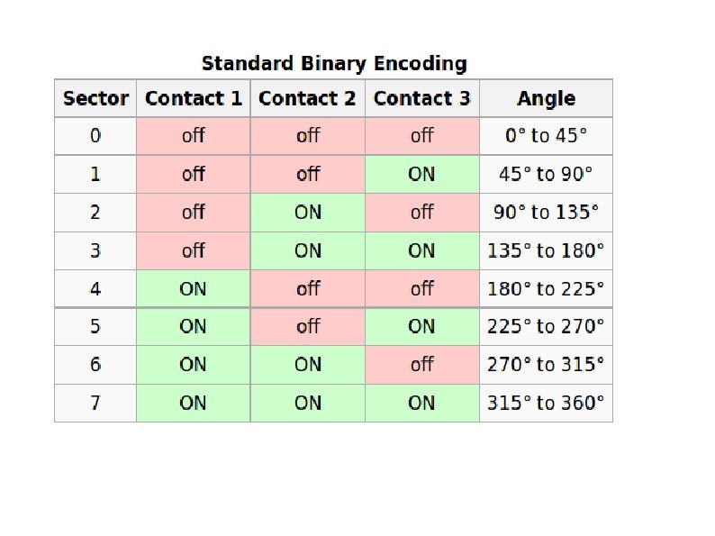
 Position 2 (Code: 001) Position 1 (Code: 000)")
Shaft encoder Position 3 (Code: 010) Position 2 (Code: 001) Position 1 (Code: 000) Position 8 (Code: 111)

Optical encoder

Self-study Gray code encoder l Incremental encoder l
- Slides: 30