Optimized Steam Condensate Systems in Refineries Improve Operational


 Assembly Parts 5 x 600#")


 contamination")


- Slides: 31
Optimized Steam & Condensate Systems in Refineries Improve Operational Reliability / Safety & Decrease Energy / Water Consumption and CO 2 Emissions
Importance of Steam in Refineries “Steam from Fuel Production provides the largest Energy Intensity Index (EII®) improvement opportunity for the majority of 2008 Fuel Study participants, and is the keydifferentiator of first-quartile performance” Solomon Associates EII® Analysis Methodology - Steam costs are valid for Europe; in the Gulf region, typically 5 – 7 $/t of steam - 1 ton of steam = 2, 8 GJ
Boiler Room Optimizations Condenser Economizer Excess O 2, Pre-heating Blow-down rate & heat recovery
Boiler Room Optimizations • • • Economizer / condenser Preheating absorbed air Oxygen rate sensor Pre-heating of feed water without steam Boiler stand-by time Boiler blow-down: – Optimal rate based on automatic blow-down, higher condensate return and improved water treatment – Using flash steam generated by the blow-down
Steam Distribution • Potential operational issues: – Mesh network – several steam sources, types of steam (superheated, saturated, flash) & pressures – Piping layout – low points, elevation, parallel pipes – Drip legs design – location, sizing and equipment – Badly operating desuperheaters – Discharge HP traps into LP lines – Start-up procedures • Potential energy issues: – Missing or damaged insulation – Leaking traps and live steam leaks
Steam Distribution – Real Case
On-site Measurements • Intrusive: – Steam flows – Pressures – Steam dryness • Surface: – Temperatures – Water hammering – Water flows
Steam Use • Potential operational and energy issues: – Steam traps failure – Condensate drainage under any conditions • Heat exchangers • Tank coils • Low-level heat exchangers (siphon drainage) – Non-Condensable Gases (NCGs) removal
Steam Trap Management 2, 500, 000 € 2, 000 € Total Costs Cost of replacement equipment (€/year) 1, 500, 000 € Manpower cost for trap station revamping (€/year) Trap testing cost (€/year) 1, 000 € Estimated operational losses (€/year) Energy losses (€/year) 500, 000 € Basic Data: - Population of 5 000 steam trap stations - Steam cost of 15 €/t -? ? € Year 1 Year 5 Costs Evolution over 5 years
Trap Management Hurdles • Hurdles – Project involving energy, process and maintenance – Consider all traps have the same importance – High equipment failure rate • Solutions – One internal Project Leader to coordinate – Make priorities in trap survey and replacement – Trap technology, sizing and piping reviewed for optimal service life
Steam Traps Management • To avoid to carbon copy when replacing frequently failing traps • To apply the right selection criterions • To take the application parameters in consideration
Most used Steam Traps for Tracing Applications • • Inverted bucket traps Bimetallic traps Thermodynamic traps Wafer traps
Selection Criterions of Steam traps for Tracing Applications Ideally the steam traps should : • Work efficiently at low load (< 5 kg/h) • Work with high back pressure • Be dirt resistant • Be freeze resistant • Fail in open position • Be environment friendly
Recommended Technologies for Steam Tracing Trapping • Instrumentation tracing : – Wafer capsule trap • Non critical temperature tracing – First choice : Bi-Metallic trap – Alternate choice : Inverted bucket trap • Critical tracing : – First choice : Inverted bucket traps – Second choice : Bi Metallic traps
Trap Management Hurdles • Hurdles – Most traps replaceable only during shut-down – Welding of replacement traps is costly (safety rules & qualified welders) – Technical mistakes could occur during replacement • Solutions – Redesign trap station to allow work at any time – Use non-welded fittings, universal connectors & flanges – Training, reporting of data critical for trap replacement, works supervision
Optimized Trap Valve Stations 750 mm ( 13 kg) Assembly Parts 5 x 600# rated globe or gate valves 1 x line strainer 12 x Sch 80 nipples 21 x 1/2’’ welds 1 x in-line “tee” 1 x Steam trap 120 mm (4 kg)
Universal Connector Technology Inverted Bucket Steam Trap Thermostatic Steam Traps Thermodynamic Steam Traps
Flooded Heat Exchangers • Typical conditions – Modulating steam control valve – Set temperature < 100°C – Back pressure in condensate return • Flooding phenomenon – Steam pressure inside of the heat exchangers decreases (even vacuum) – Differential pressure at trap becomes negative – When product temperature drops, control valve opens completely – Water hammering, corrosion, unstable temperature, gasket leaking
Solutions = Double Duty Pumping traps Motive pressure DD-12 Pumping capacity: 7. 800 kg/h max. Trapping capacity: 42. 200 kg/h max. Motive pressure : 14 bar Back pressure : 5, 6 bar
Siphon Drainage of Condensate Steam Condensate Open Valve Sulfur Tank
Condensate Return • Improving condensate return rate: – Piping sizing – Handling (possible) contamination • Flash steam recovery and usage: – Flash tank – Steam Ejector • Avoiding water hammering: – Separating flash / live steam from condensate – Mixing cold and hot condensate
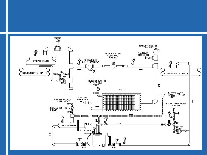
Typical installation of Air Heater
Optimized proposal for steam heated air heater
Increasing Condensate Recovery • Savings through condensate return – Higher sensible heat (up to 90°C instead of 15°C for feedwater) – Decreases feedwater consumption – Low conductivity condensate decreases water treatment and boiler blow-down rate
Increasing Flash Steam Recovery • Flash Steam – Caused by revaporisation of part of condensate after a pressure drop – Flash steam enthalpy equals or exceeds the sensible heat of remaining condensate – Could be recovered at flashing pressure or mixed (through ejectors) with high pressure steam to make average pressure steam
High Pressure in Condensate Return
Flash Steam in Condensate Return
Increasing Flash Steam Recovery • Thermo-Syphon Mixer: – allows mixing gently hot and cold condensate – thermodynamic loop: circulation due to weight difference between cold and hot condensate – no pumps needed – starts/stops based on presence of hot condensate
Steam 8" 3" condensate 1 m mi ni 36 0 3" condensate 2 m mini
Summary of Potential Optimizations Steam and Hot Water Best Practices ADVANCED PROJECTS High Savings/Investments 3. 0 % Cond. Economizer 2. 5 % Heat Recovery LOW HANGING FRUIT Low/No Investments FW Economizer 2. 0 % Condensate Return Leaking Traps Lower St. Pressure Bd Reduction 1. 5 % BASIC PROJECTS Low Investments O 2 Trim Insulation Steam Leaks BDHR 1. 0 % Flash Steam Rec. Vent Condenser 0. 5 % 0. 0 0. 5 1. 0 1. 5 2. 0 Payback time (in years) 2. 5 3. 0 3. 5 Savings (% of Steam Generation Costs) 3. 5 %