Optics Design of the CEPC Interaction Region Yiwei


- Slides: 30

Optics Design of the CEPC Interaction Region Yiwei Wang, Dou Wang, Sha Bai, Huiping Geng, Feng Su, Tianjian Bian, Yingshun Zhu, Jie Gao, Gang XU Accelerator Center, IHEP CEPC 2014, Shanghai 12 Sep 2014

Outline • Introduction • Optics Design of the Interaction Region for L*=2. 5 m • Primary Optics Design of the Interaction Region for L*=1. 5 m • Summary and Further Work

Introduction • Functions of Interaction Region (IR) optics – Provide very small beta function to achieve very small beam size: βy*=1. 2 mm, σy*=0. 16 um, for CEPC – Correct large chromaticity due to small beta function: W~L*/ βy* IP FT CCY CCX MT FT: final telescopic transformer CCY: chromatic correction section Y M=-I CCX: chromatic correction section X M=-I CEPC IR L*=1. 5 m, Sep 2014, by Yiwei Wang MT: matching telescopic transformer

Introduction • In the past several months we worked on a IR design for L*=2. 5 m – IR Optics and optimization dynamic aperture of whole ring – Dynamic aperture is small due to large chromaticity at final doublet which is difficult to well correct – Reduce chromaticity at final doublet by reducing L* from 2. 5 m to 1. 5 m • primary design for L*=1. 5 m due to time being

Optics Design of the Interaction Region (L*=2. 5 m) • Based on Yunhai Cai’s design L*=2. 5 m βx*=0. 8 m βy*=1. 2 mm entrance βx*=75. 6 m βy*=25. 6 m

Final Doublet lattice function (L*=2. 5 m) IP L*=2. 5 m Q 1: L=0. 56 m, G=-516 T/m D 2=1. 14 m Q 2: L=0. 58 m, G=364 T/m

The tune dependence on the energy deviation

Dynamic Aperture (L*=2. 5 m) With IR DA for 2%, -2% is 0 3 y 5 x

Dynamic Aperture (L*=2. 5 m) DA for 2%, -2% is 0 4 y By Dou Wang and Demin Chou 5 x

Optimization of the Bandwidth with Octupoles • Octupoles are placed beside each sextupoles Octupole By Feng SU, Aug 2014

Optimization of the Bandwidth with Octupoles By Feng SU, Aug 2014 K 3=0 K 3=15. 5 • DA for on momentum decreased Ø may due to too many octupoles Ø to optimize the number of octupoles and their positions

Optimize the bandwidth by adjusting working point • Optimize the bandwidth by adjusting working point – Idea from CERN people – After reaching the quadrupoles and sextupoles in the ARC, the tune changes, and the momentum bandwidth for x plane is more flat By Sha BAI, Aug 2014

Optimize the bandwidth by adjusting working point On momentum (dp=0) Off momentum (dp=2%) By Sha BAI, Aug 2014

Optimize the bandwidth by adjusting working point • After optimization the momentum bandwidth using the quadrupoles and sextupoles in the Ring, the dynamic aperture in the phase space seems no change. – strong chromatic aberrations in the IR should be the main reason – should go back to optimize the IR

Primary IR optics with L*=1. 5 m (1) • betx*=0. 8 m, bety*=1. 2 mm, L*=1. 5 m IP FT CCY CCX MT Yiwei Wang, 3 Sep 2014 FT: final telescopic transformer CCY: chromatic correction section y CCX: chromatic correction section x MT: matching telescopic transformer

Final Telescopic Transformer IP Q 1 Q 2 L*(D 1) =1. 5 m Q 1: L=0. 76 m, G=-400 T/m D 2=2. 45 m Q 2: L=0. 42 m, G=283 T/m

Optics of whole ring • IR+ARC

Dynamic Aperture • On momentum Off momentum: 2%, 1%

Primary IR design for L*=1. 5 m (2) Yiwei Wang, 11 Sep 2014 IP FT CCY CCX MT L*=1. 5 m βx*=0. 8 m βy*=1. 2 mm entrance βx*=75. 6 m βy*=25. 6 mm CEPC IR L*=1. 5 m, Sep 2014, by Yiwei Wang

Final Doublet lattice function (L*=1. 5 m) IP L*=1. 5 m Q 1: L=1. 25 m, G=-300 T/m D 2=0. 5 m Q 2: L=0. 72 m, G=300 T/m

Chromatic Correction • with total 4 sextupoles in the chromatic correction – For the first try, zero length of sextupoles are used to neglect the finite length effect. – bandwidth of horizontal plane quite good but vertical plane need to be optimized

Beam stay-clear region – Rx=5 σx_inj, Ry=5 σy_inj – x_inj=21. 8 nm, y_inj=2. 2 nm (assume 10% coupling for injection beam) – Inner radius of vacuum chamber at Q 1 and Q 2: 1. 3 cm IP Q 1 Q 2 [m] • Final Doublet L*=1. 5 m Q 1: L=1. 25 m, Rin=1. 3 cm, G=-300 T/m, Rout=20 cm, Lact=1. 6 m D 2=0. 5 m Q 2: L=0. 72 m, Rin=1. 3 cm, G=300 T/m, Rout=20 cm, Lact=1. 05 m vacuum chamber Ry Rx Out aperture of quadrupoles estimated by Yingshun Zhu

Beam stay-clear region (L*=2. 5 m) – Rx=5 σx_inj, Ry=5 σy_inj – x_inj=21. 8 nm, y_inj=2. 2 nm (assume 10% coupling for injection beam) – Inner radius of vacuum chamber at Q 1 and Q 2: 1. 8 cm IP Q 1 Q 2 [m] • Final Doublet vacuum chamber L*=2. 5 m Q 1: L=0. 56 m, R=1. 8 cm, G=-516 T/m D 2=1. 14 m Q 2: L=0. 58 m, R=1. 8 cm, G=364 T/m Ry Rx

Primary IR design for L*=1. 5 m • get a primary IR optics design for L*=1. 5 m due to time being • The work on dynamic aperture with IR in undergoing.

Summary • Several method to optimizing dynamic aperture for the IR Optics L*=2. 5 m have been tried – transfer matrix to instead real arc In order to optimize the IR independent of ARC – Optimization of bandwidth with Octupoles – Optimize the bandwidth by adjusting working point – Dynamic aperture is small due to large chromaticity at final doublet which is difficult to well correct • Reduce chromaticity at final doublet by reducing L* from 2. 5 m to 1. 5 m – primary design for L*=1. 5 m due to time being – The work on dynamic aperture with IR in undergoing.

Further Work • Further optimize IR bandwidth with transfer matrix for the ARC • Further optimize the aperture with IR and ARC together

Reserved

CEPC Dynamic Aperture (ARC only) • Dynamic Aperture of the ring with ARC only – IR optics is replaced by the straight section with same length – Working point: 206. 08/206. 22 Without FFS 509. 3σy 2%, -2%的孔径是 0 1%,-1% On momentum 59. 2σx

CEPC lattice with IR In this design: • Circumference: 52. 1 km • 16*arcs: 2. 64 km (60 FODO) • 12*short straight: 352 m (8 FODO) • 4*long straight: ~700 m • Bending radius: 5. 7 km • U 0: 3. 77 Ge. V • Nature emittance: 7. 67 nm • Nature energy spread: 0. 19% • Nature bunch length : 2. 82 mm • Momentum compaction: 3. 3 E-5

Treat arcs as transfer matrix • Calculate transfer matrix for arc 1 and arc 2 by SAD. • Join the real lattice for IP 1 and IP 3 with the matrix of two arcs. • Track DA by SAD for the faked ring (240 turns). Ø two “point” cavities at IP 2 and IP 4
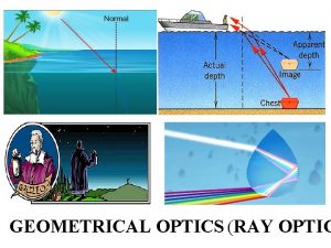
 Difference between ray optics and wave optics
 Venn diagram of geometric optics and physical optics
 Cepc logo
 Cepc logo
 M
M Active region and saturation region
 Rainbow optics star spectroscope
 Ecological optics
 Turba optics
 Optical power loss
 Unilab
 Bill nye reflection and refraction
 Grade 10 optics review
 Basic electricity and optics
 Bill nye light optics worksheet
 Plane mirror diagram
 Hotwire fiber optics
 Single slit envelope
 Http //www.phys.hawaii.edu/ teb/optics/java/slitdiffr/
 With the rule astigmatism axis
 Geometric optics problems
 Fourier optics
 Vergence formula
 The computational complexity of linear optics
 Smells law
 Bill nye light energy
 Introduction to fiber optics
 Cauchy formula optics
 Adaptive optics
 What is optics
 Geometric optics ppt

