Optical Telemetry and Safety Measures Zankhana Mehta Reflection


 • The buffer of a fiber")


")
")


- Slides: 63
Optical Telemetry and Safety Measures Zankhana Mehta
Reflection
Refraction
History of Fiber Optics John Tyndall demonstration in 1870 Total Internal reflection is the basic idea of fiber optic
What Is Fiber Optics ? • Transmitting communications signals over hair thin strands of glass or plastic • Not a "new" technology • Concept a century old • Used commercially since 1980
Fiber Technology A glass optical fiber is about twice the size of a human hair.
How Fiber Works
Advantages of Fiber Optics • fiber optic cables can be used for longer distances before the signal is amplified or repeated. • Data transmission using a fiber optic cable is many times faster than with electrical methods • The speeds of over 10 Gbps are possible with fiber optic. • Fiber optic cables deliver more reliable transmissions over greater distances, although at a somewhat greater cost. • Light signals do not interfere with other signals. As a result, fiber optic • connections can be used in extremely adverse environments • Higher Bandwidth.
Advantages of Fiber Optics • Optical fiber cables do not conduct electricity and so eliminate problems of ground loops, lightning damage and electrical shock when cabling in high voltage areas. • Fiber optic cables are generally much thinner and lighter than copper cable. • Fiber optic cables have greater data security than copper cables.
Fiber Is Everywhere! It’s how we communicate…
Fiber optic cable components
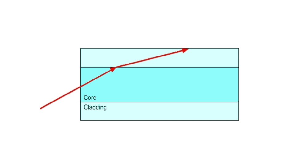
Fiber optic cable components. . Fiber core • The core of fiber optic telecommunications cable consists of glass fibers through which the light signal travels. • The most common core sizes are 50 and 62. 5 micrometers Cladding • The core and cladding are actually manufactured as a single unit. • The cladding is a protective layer with a lower index of refraction than the core. • The lower index means any light that hits the core walls will be redirected back to continue on its path. • The cladding diameter is typically 125 microns.
Fiber optic cable components… Fiber optic buffer (jacket) • The buffer of a fiber optic cable is made of one or more layers of plastic surrounding the cladding. • The buffer helps strengthen the cable, thereby decreasing the likelihood of micro cracks, which can eventually break the fiber. • The buffer also protects the core and cladding from potential invasion by water or other materials in the operating environment. • The buffer typically doubles the diameter of the fiber.
How Does fiber optic transmit light
Fibre optic Cable • Single Mode Fiber Optic Cable • Multi-Mode Fiber Optic Cable
Single Mode Fiber Optic Cable • Single Mode fiber optic cable has a small diametral core that allows only one mode of light to propagate Because of this, the number of light reflections created as the light passes through the core decreases, lowering attenuation and creating the ability for the signal to travel further.
Application • long distance Communication • Higher bandwidth runs by Telcos, • CATV companies • Colleges and Universities
Multimode Fiber Optic Cable • Multimode fiber optic cable has a large diametral core that allows multiple modes of light to propagate Because of this, the number of light reflections created as the light passes through the core increases, creating the ability for more data to pass through at a given time.
Application • Typically used for short distance • Data and audio/video applications in LANs • RF broadband signals
Types of optical fiber • Step-index cable • Graded-index cable
Step-index cable • Cable with an abrupt change in refraction index is called step-index cable. • In step-index cable, the change is made in a single step. • Single-step multimode cable uses this method, and it is the simplest, least expensive type of fiber optic cable.
Step-index cable
Graded-index cable • Cable with a gradual change in refraction index is called graded-index cable. • This fiber optic cable type has a relatively wide core. • The change occurs gradually and involves several layers, each with a slightly lower index of refraction. • A gradation of refraction indexes controls the light signal better than the stepindex method.
Graded-index cable
Fibre components: • Switches • Couplers • Splitters • Fibre optic Connectors
Switches • One to many
Switches
Couplers • A fibre optic coupler is a device used in optical fibre systems with one or more input fibres and one or several output fibres.
Light entering an input fibre can appear at one or more outputs and its power distribution potentially depending on the wavelength and polarization
Splitters • A fiber optic splitter, also known as a beam splitter, is based on a quartz substrate of an integrated waveguide optical power distribution device
Splitters • Wave splitting involves dividing a light beam into multiple streams. The daughter streams can be equal or in some other ratio.
Fiber Optic Connectors • Terminates the fibers • Connects to other fibers or transmission equipment
Fiber Optic Data Links
Connector FC MIC LC Figure Full Name Ferrule Connector or Fiber Channel Media Interface Connector Little Connector or Local Connector Fibre Type Applications SM, MM Datacom, Telecommunicati ons Fiber Optic Network High Density Interconnection MT Array Mechanical Transfer SM, MM SC Standard Connector SM, MM Datacom SC Duplex SC - Dual Contact SM, MM Datacom SM, MM Inter-/Intra. Building, Security, Navy ST Straight Tip
Parts of Connectors Ø Fiber optic connectors are unique. Ø Fiber cables transmit pulses of light instead of electrical signals, so the terminations must be much more precise. Ø Instead of merely allowing pins to make metal-to-metal contact, fiber optic connectors must align microscopic glass fibers perfectly in order to allow for Ø There are three major components of a fiber connector: the ferrule, the connector body, the coupling mechanism.
What is Ferrual • a ring or cap, typically a metal one, which strengthens the end of a handle, stick, or tube and prevents it from splitting or wearing.
Connector body • Connector body — this is a plastic or metal structure that holds the ferrule and attaches to the jacket and strengthens members of the fiber cable itself.
Coupling mechanism • Coupling mechanism — this is a part of the connector body that holds the connector in place when it gets attached to another device (a switch, NIC, bulkhead coupler, etc. ). • It may be a latch clip, a bayonet-style nut, or similar device.
Steps for installing a fiber optical connector
Cleaning • Cleaning Fiber to avoid dust and debries ingrass inside the core while installing
Cleaving • Cleaving involves cutting the fiber end flush with the end of the ferrule
Polishing After a clean cleave has been achieved, the fibre end face is attached to a polishing brush, and the fibre is ground and polished
Procedure to test an installed fiber optic connector
Procedure to test an installed fiber optic connector
The effects on OFC : Back reflection
Back reflection • The general knowledge has been that backreflections hurt the performance of a link because the reflected light gets into the laser cavity, disturbs the standing optical wave, and creates noise.
Solution of Back reflection Issue • Opto Isolator Traditional magnetic-optical isolator with a reflection mirror at the output port.
Optical Isolators
Elements of Optical Telemetry
The advantages of fiber optic over wire cable • Thinner • Higher carrying capacity • Less signal degradation • Light signal • Low power • Flexible • Non-flammable • Lightweight
Disadvantage of fiber optic over copper wire cable • Optical fiber is more expensive per meter than copper • Optical fiber can not be join together as easily as copper cable. It requires training and expensive splicing and measurement equipment.
Fiber Is Everywhere! It’s how we communicate…
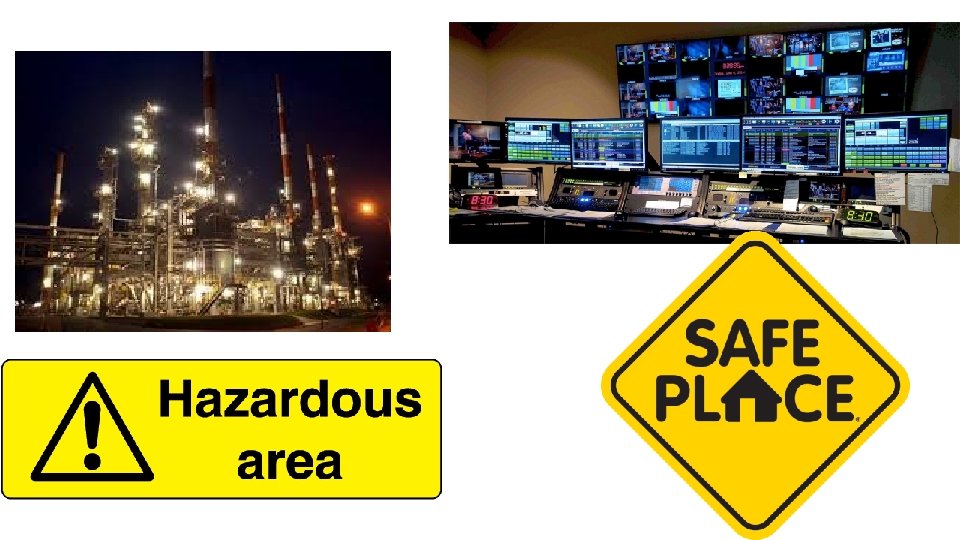
Safety measures in process telemetry Zankhana Mehta
Telemetry • Transfers Signals from one end to another end. • If signals are needed to transfer from hazardous area to safe area. • We need some mechanism to keep safe area “SAFE”.
Safety Measures in Telemetry • Isolation of signals from Hazardous area to Safe area • Suppression of any high voltage hike or extra current flow to safe area • Creating a protection layer between soft machinery and process field
Safety barrier (zone)
Safety barrier (Actual image)
Isolation of signal: Optical
Isolation of signal : Electrical
Installation in Industry
How to test Safety Barriers 1. For testing identify the tag number of safety barrier which has to be tested 2. Install the additional 24 VDC supply at the input terminal of the safety barrier 3. Check the out LEDs on barrier for the visual indication 4. Also check the output terminal for the desired output 5. If it is working proper it will give its desired output otherwise it will show Error LED or abrupt output. 6. After the test will over remove the supply from the daughter card