
Optical links Andrea Borga andrea borganikhef nl A
Optical links Andrea Borga andrea. borga@nikhef. nl A. Borga Electronics. Technolog y Department February 4, 2015 ISOTDAQ 2015 – Rio de Janeiro A. Borga Electronics Technology Department 1
Outline What can we do with fibres? Technology highlights Why optics? How optics? Where optics? Applications of optical links (for HEP) Data links A. Borga Electronics. Technolog y Department Timing and trigger Pure Timing February 4, 2015 ISOTDAQ 2015 – Rio de Janeiro A. Borga Electronics Technology Department 2
Technology highlights A. Borga Electronics. Technolog y Department February 4, 2015 ISOTDAQ 2015 – Rio de Janeiro A. Borga Electronics Technology Department 3
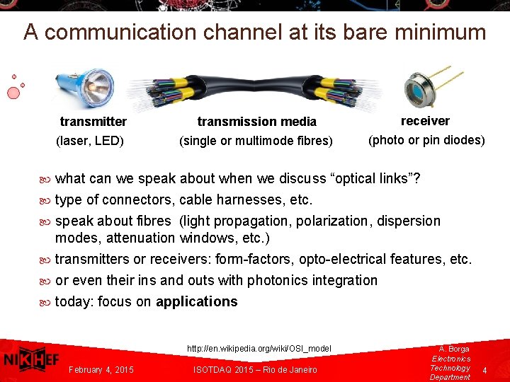
A communication channel at its bare minimum transmitter transmission media receiver (laser, LED) (single or multimode fibres) (photo or pin diodes) what can we speak about when we discuss “optical links”? type of connectors, cable harnesses, etc. speak about fibres (light propagation, polarization, dispersion modes, attenuation windows, etc. ) transmitters or receivers: form-factors, opto-electrical features, etc. or even their ins and outs with photonics integration A. Borga today: focus on applications Electronics Technolog y Department http: //en. wikipedia. org/wiki/OSI_model February 4, 2015 ISOTDAQ 2015 – Rio de Janeiro A. Borga Electronics Technology Department 4
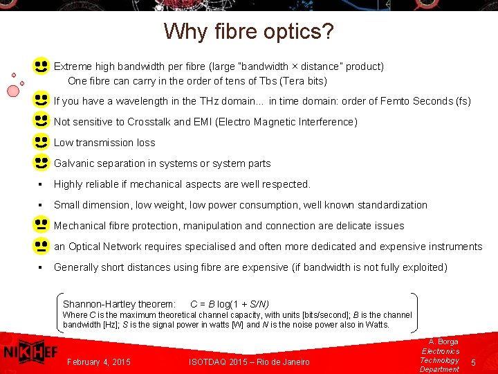
Why fibre optics? § Extreme high bandwidth per fibre (large ”bandwidth × distance” product) One fibre can carry in the order of tens of Tbs (Tera bits) § If you have a wavelength in the THz domain… in time domain: order of Femto Seconds (fs) § Not sensitive to Crosstalk and EMI (Electro Magnetic Interference) § Low transmission loss § Galvanic separation in systems or system parts § Highly reliable if mechanical aspects are well respected. § Small dimension, low weight, low power consumption, well known standardization § Mechanical fibre protection, manipulation and connection are delicate issues § an Optical Network requires specialised and often more dedicated and expensive instruments § Generally short distances using fibre are expensive (if bandwidth is not fully exploited) A. Borga Electronics. Technolog y Department Shannon-Hartley theorem: C = B log(1 + S/N) Where C is the maximum theoretical channel capacity, with units [bits/second]; B is the channel bandwidth [Hz]; S is the signal power in watts [W] and N is the noise power also in Watts. February 4, 2015 ISOTDAQ 2015 – Rio de Janeiro A. Borga Electronics Technology Department 5
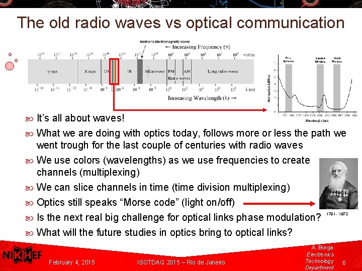
The old radio waves vs optical communication It’s all about waves! What we are doing with optics today, follows more or less the path we went trough for the last couple of centuries with radio waves We use colors (wavelengths) as we use frequencies to create channels (multiplexing) We can slice channels in time (time division multiplexing) Optics still speaks “Morse code” (light on/off) A. Borga Is the next real big challenge for optical links phase modulation? Electronics. Technolog y What will the future studies in optics bring to optical links? 1791 - 1872 Department February 4, 2015 ISOTDAQ 2015 – Rio de Janeiro A. Borga Electronics Technology Department 6
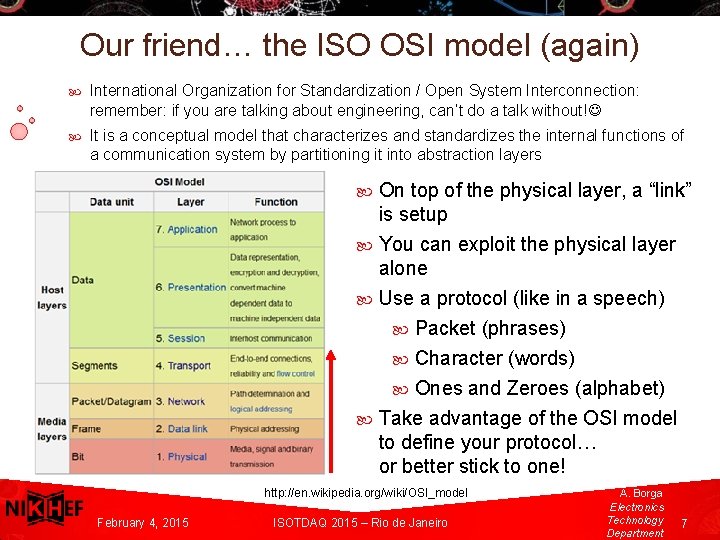
Our friend… the ISO OSI model (again) International Organization for Standardization / Open System Interconnection: remember: if you are talking about engineering, can’t do a talk without! It is a conceptual model that characterizes and standardizes the internal functions of a communication system by partitioning it into abstraction layers On top of the physical layer, a “link” is setup You can exploit the physical layer alone Use a protocol (like in a speech) Packet (phrases) Character (words) Ones and Zeroes (alphabet) Take advantage of the OSI model to define your protocol… or better stick to one! A. Borga Electronics. Technolog y Department http: //en. wikipedia. org/wiki/OSI_model February 4, 2015 ISOTDAQ 2015 – Rio de Janeiro A. Borga Electronics Technology Department 7
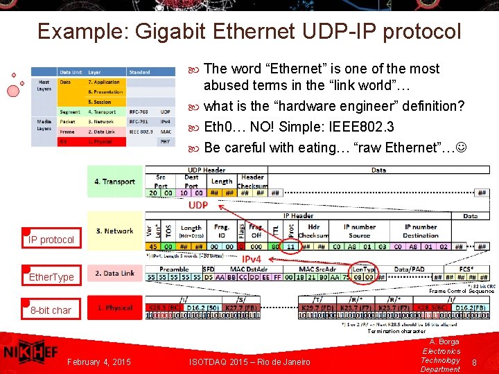
Example: Gigabit Ethernet UDP-IP protocol The word “Ethernet” is one of the most abused terms in the “link world”… what is the “hardware engineer” definition? Eth 0… NO! Simple: IEEE 802. 3 Be careful with eating… “raw Ethernet”… IP protocol Ether. Type Frame Control Sequence A. Borga Electronics 8 -bit char Technolog y Department February 4, 2015 Termination character ISOTDAQ 2015 – Rio de Janeiro A. Borga Electronics Technology Department 8
Data transmission on optical links A. Borga Electronics. Technolog y Department February 4, 2015 ISOTDAQ 2015 – Rio de Janeiro A. Borga Electronics Technology Department 9
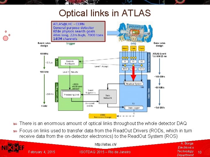
Optical links in ATLAS A. Borga There is an enormous amount of optical links throughout the whole detector DAQ Electronics Focus on links used to transfer data from the Read. Out Drivers (RODs, which in turn Technolog y receive data from the on-detector electronics) to the Read. Out System (ROS) Department A. Borga http: //atlas. ch/ February 4, 2015 ISOTDAQ 2015 – Rio de Janeiro Electronics Technology Department 10
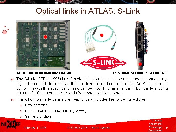
Optical links in ATLAS: S-Link Muon chamber Read. Out Driver (MROD) ROS - Read. Out Buffer INput (Robin. NP) The S-Link (CERN, 1995) is a Simple Link Interface which can be used to connect any layer of front-end electronics to the next layer of read-out electronics. An S-Link is a link complying with this specification and can be thought of as a virtual ribbon cable, moving data (at 2. 0 Gbps) or control words from one point to another In addition to simple data movement, S-Link includes the following features; A. Borga o Electronics. Technolog o y Department o Error detection Return channel for flow control (“XOFF”) Self-test function February 4, 2015 ISOTDAQ 2015 – Rio de Janeiro A. Borga Electronics Technology Department 11
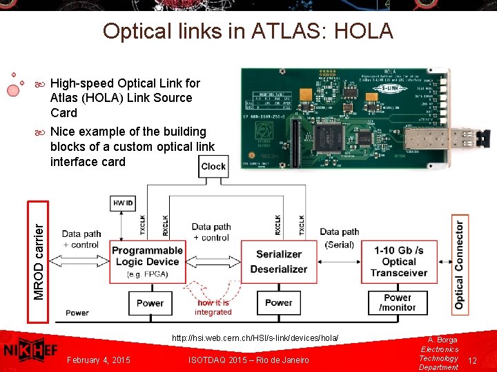
Optical links in ATLAS: HOLA High-speed Optical Link for Atlas (HOLA) Link Source Card Nice example of the building blocks of a custom optical link interface card MROD carrier A. Borga Electronics. Technolog y Department http: //hsi. web. cern. ch/HSI/s-link/devices/hola/ February 4, 2015 ISOTDAQ 2015 – Rio de Janeiro A. Borga Electronics Technology Department 12
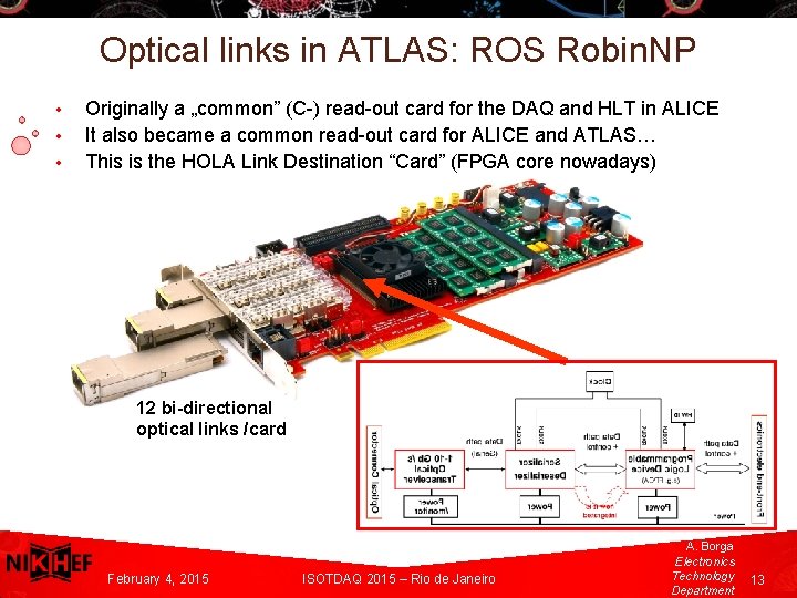
Optical links in ATLAS: ROS Robin. NP • • • Originally a „common” (C-) read-out card for the DAQ and HLT in ALICE It also became a common read-out card for ALICE and ATLAS… This is the HOLA Link Destination “Card” (FPGA core nowadays) 12 bi-directional optical links /card A. Borga Electronics. Technolog y Department February 4, 2015 ISOTDAQ 2015 – Rio de Janeiro A. Borga Electronics Technology Department 13
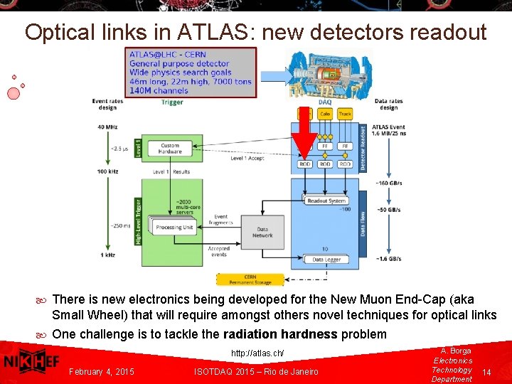
Optical links in ATLAS: new detectors readout A. Borga There is new electronics being developed for the New Muon End-Cap (aka Electronics. Small Wheel) that will require amongst others novel techniques for optical links Technolog y One challenge is to tackle the radiation hardness problem Department A. Borga http: //atlas. ch/ February 4, 2015 ISOTDAQ 2015 – Rio de Janeiro Electronics Technology Department 14
Radiation hardness problem • CERN/LHC: serious need for a common, radiation hard high-speed digital link that can deliver data, control and trigger information on the same physical link to on-detector eletronics: o Radiation hardness o Error detection and correction o Constant latency o Light-weight (for transparency to particles) o Intense magnetic field resistant • Common development efforts driven by CMS and ATLAS (and LHCb) • Results: the Versatile Link and the GBT protocol (and ASICs) A. Borga Electronics • Technolog y Department CERN provides: components, test boards, firmware and other support https: //espace. cern. ch/GBT-Project/default. aspx https: //espace. cern. ch/project-versatile-link/public/default. aspx February 4, 2015 ISOTDAQ 2015 – Rio de Janeiro A. Borga Electronics Technology Department 15
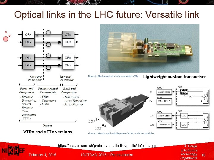
Optical links in the LHC future: Versatile link Lightweight custom transceiver Laser Driver A. Borga Electronics. Technolog VTRx and VTTx versions y Department https: //espace. cern. ch/project-versatile-link/public/default. aspx February 4, 2015 ISOTDAQ 2015 – Rio de Janeiro A. Borga Electronics Technology Department 16
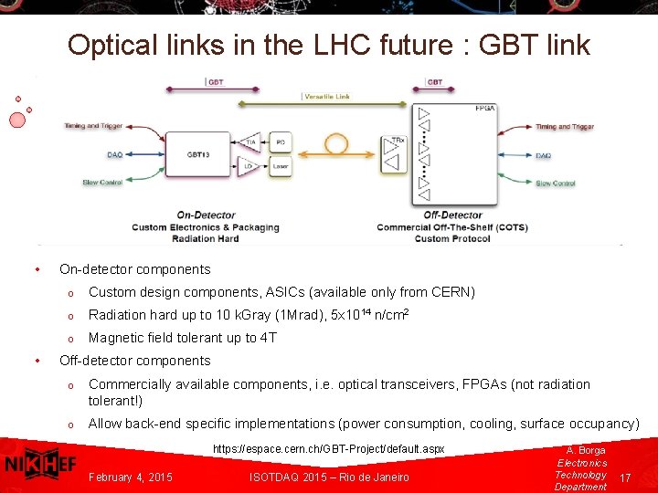
Optical links in the LHC future : GBT link • • On-detector components o Custom design components, ASICs (available only from CERN) o Radiation hard up to 10 k. Gray (1 Mrad), 5 x 10¹⁴ n/cm 2 o Magnetic field tolerant up to 4 T Off-detector components o A. Borga Electronics. Technolog o y Department Commercially available components, i. e. optical transceivers, FPGAs (not radiation tolerant!) Allow back-end specific implementations (power consumption, cooling, surface occupancy) https: //espace. cern. ch/GBT-Project/default. aspx February 4, 2015 ISOTDAQ 2015 – Rio de Janeiro A. Borga Electronics Technology Department 17
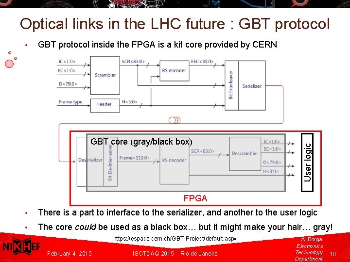
Optical links in the LHC future : GBT protocol inside the FPGA is a kit core provided by CERN GBT core (gray/black box) User logic • FPGA A. Borga Electronics • There is a part to interface to the serializer, and another to the user logic Technolog y • The core could be used as a black box… but it might make your hair… gray! Department https: //espace. cern. ch/GBT-Project/default. aspx A. Borga February 4, 2015 ISOTDAQ 2015 – Rio de Janeiro Electronics Technology Department 18
… it is not all about CERN A. Borga Electronics. Technolog y Department February 4, 2015 ISOTDAQ 2015 – Rio de Janeiro A. Borga Electronics Technology Department 19
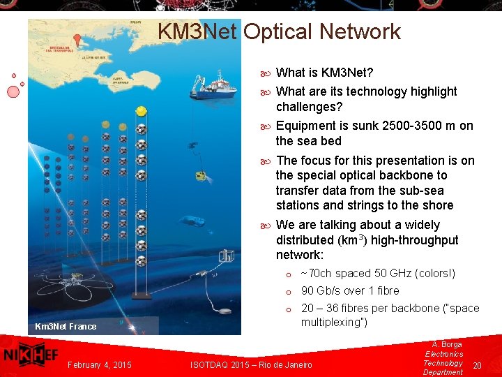
KM 3 Net Optical Network A. Borga Electronics. Technolog y Km 3 Net France Department February 4, 2015 What is KM 3 Net? What are its technology highlight challenges? Equipment is sunk 2500 -3500 m on the sea bed The focus for this presentation is on the special optical backbone to transfer data from the sub-sea stations and strings to the shore We are talking about a widely distributed (km 3) high-throughput network: o ~70 ch spaced 50 GHz (colors!) o 90 Gb/s over 1 fibre o 20 – 36 fibres per backbone (“space multiplexing”) ISOTDAQ 2015 – Rio de Janeiro A. Borga Electronics Technology Department 20
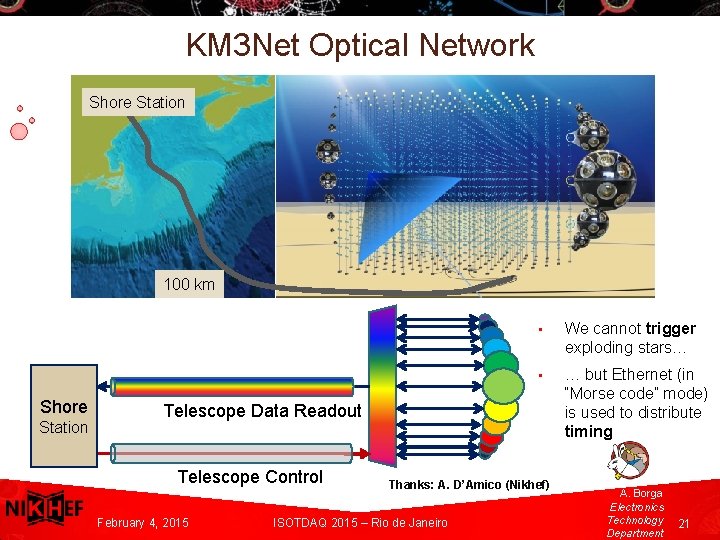
KM 3 Net Optical Network Shore Station 100 km Shore A. Borga Station Electronics. Technolog y Department • We cannot trigger exploding stars… • … but Ethernet (in “Morse code” mode) is used to distribute timing Telescope Data Readout Telescope Control February 4, 2015 Thanks: A. D’Amico (Nikhef) ISOTDAQ 2015 – Rio de Janeiro A. Borga Electronics Technology Department 21
Timing and Trigger on optical links A. Borga Electronics. Technolog y Department February 4, 2015 ISOTDAQ 2015 – Rio de Janeiro A. Borga Electronics Technology Department 22
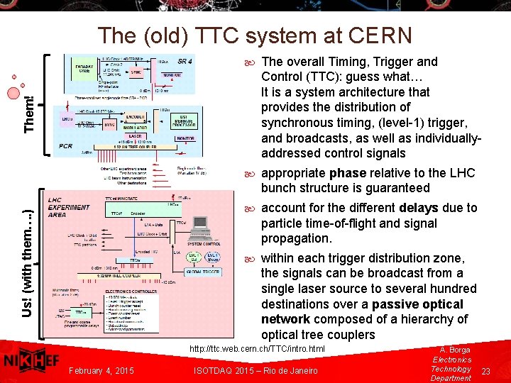
The (old) TTC system at CERN The overall Timing, Trigger and Control (TTC): guess what… It is a system architecture that provides the distribution of synchronous timing, (level-1) trigger, and broadcasts, as well as individuallyaddressed control signals appropriate phase relative to the LHC bunch structure is guaranteed account for the different delays due to particle time-of-flight and signal propagation. within each trigger distribution zone, the signals can be broadcast from a single laser source to several hundred destinations over a passive optical network composed of a hierarchy of optical tree couplers Us! (with them…. ) Them! A. Borga Electronics. Technolog y Department http: //ttc. web. cern. ch/TTC/intro. html February 4, 2015 ISOTDAQ 2015 – Rio de Janeiro A. Borga Electronics Technology Department 23
The TTC system: needs some refresh Desired features of a new system Backward compatibility with legacy TTC system Bi-directionality Increased bandwidth Common system Scalability, partitioning flexibility Better performances than TTC for clock recovery (i. e. better clocks) Low and fixed latency (opens possibility to do time-stamping at the ROS) Candidates: GBT Links and Passive Optical Networks (PONs) A. Borga GBT: ideal for detectors environments, presently the only rad hard multi-gigabit Electronics- optical link with deterministic latency Technolog y Passive Optical Networks offer the ideal gear for backbone distribution Department http: //ttc. web. cern. ch/TTC/intro. html A. Borga February 4, 2015 ISOTDAQ 2015 – Rio de Janeiro Electronics Technology Department 24
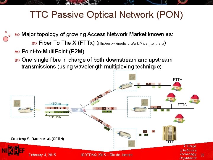
TTC Passive Optical Network (PON) Major topology of growing Access Network Market known as: Fiber To The X (FTTx) (http: //en. wikipedia. org/wiki/Fiber_to_the_x) Point-to-Multi. Point (P 2 M) One single fibre in charge of both downstream and upstream transmissions (using wavelength multiplexing technique) FTTH B 1 ONU 1 1 2 B 1 3 1 1 1 B 2 1 1490 nm 1 OLT 1 2 1 B 1 2 1 1 2 3 1 1 2 B 2 2 3 3 3 1310 nm 1 2 3 1 ONU 2 2 2 FTTC 2 2 1 2 B A. Borga Electronics. Technolog y Courtesy S. Baron et al. (CERN) Department February 4, 2015 1 3 3 3 1 3 B 3 ONU 3 3 3 FTTB ISOTDAQ 2015 – Rio de Janeiro A. Borga Electronics Technology Department 25
Pure Timing on optical links A. Borga Electronics. Technolog y Department February 4, 2015 ISOTDAQ 2015 – Rio de Janeiro A. Borga Electronics Technology Department 26
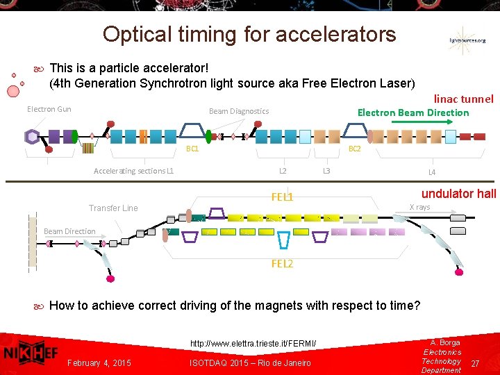
Optical timing for accelerators This is a particle accelerator! (4 th Generation Synchrotron light source aka Free Electron Laser) linac tunnel Electron Gun Electron Beam Direction Beam Diagnostics BC 1 Accelerating sections L 1 Transfer Line BC 2 L 2 FEL 1 L 3 L 4 undulator hall X rays Beam Direction FEL 2 A. Borga Electronics How to achieve correct driving of the magnets with respect to time? Technolog y Department A. Borga http: //www. elettra. trieste. it/FERMI/ February 4, 2015 ISOTDAQ 2015 – Rio de Janeiro Electronics Technology Department 27
Optical timing for accelerators Two class of signals are needed: • aux signals (triggers and low-performance clock signals) o the machine is pulsed, hence the acquisition is not continuous but event based, therefore event-labelling for post-processing of data is required • Ultra-stable phase reference signals (“clocks”) o used to synchronize key elements of the machine (klystrons, lasers, special diagnostics as the Bunch Arrival Monitor (BAM), etc. ) Why optical? large scale facilities (100 s meters – a few km) with demanding requirements (10 s femtosecond level stability). A. Borga Electronics. Optical techniques are available to achieve the result! Technolog y Department February 4, 2015 ISOTDAQ 2015 – Rio de Janeiro A. Borga Electronics Technology Department 28
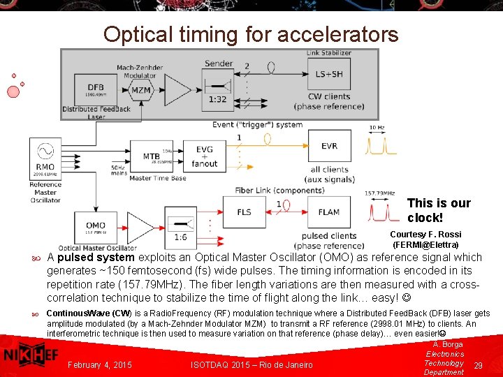
Optical timing for accelerators This is our clock! Courtesy F. Rossi (FERMI@Elettra) A pulsed system exploits an Optical Master Oscillator (OMO) as reference signal which generates ~150 femtosecond (fs) wide pulses. The timing information is encoded in its repetition rate (157. 79 MHz). The fiber length variations are then measured with a crosscorrelation technique to stabilize the time of flight along the link… easy! A. Borga Electronics Continous. Wave (CW) is a Radio. Frequency (RF) modulation technique where a Distributed Feed. Back (DFB) laser gets Technolog amplitude modulated (by a Mach-Zehnder Modulator MZM) to transmit a RF reference (2998. 01 MHz) to clients. An y Departmentinterferometric technique is then used to measure variation on that reference (phase delay)… even easier! February 4, 2015 ISOTDAQ 2015 – Rio de Janeiro A. Borga Electronics Technology Department 29
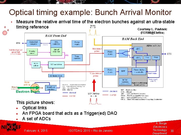
Optical timing example: Bunch Arrival Monitor • Measure the relative arrival time of the electron bunches against an ultra-stable timing reference Courtesy L. Pavlovic (FERMI@Elettra) Electron Beam This picture shows: Optical links An FPGA board that acts as a Trigger(ed) DAQ A set of ADCs A. Borga Electronics. Technolog y Department February 4, 2015 ISOTDAQ 2015 – Rio de Janeiro A. Borga Electronics Technology Department 30
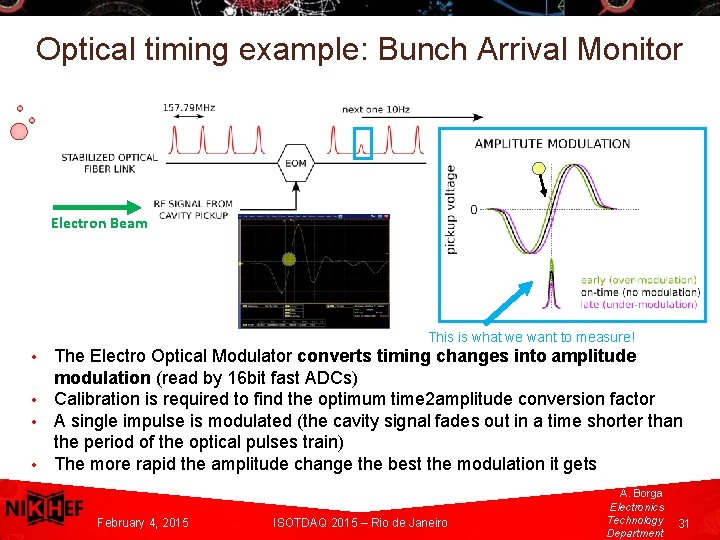
Optical timing example: Bunch Arrival Monitor Electron Beam This is what we want to measure! The Electro Optical Modulator converts timing changes into amplitude modulation (read by 16 bit fast ADCs) • Calibration is required to find the optimum time 2 amplitude conversion factor • A single impulse is modulated (the cavity signal fades out in a time shorter than A. Borga Electronicsthe period of the optical pulses train) Technolog y • The more rapid the amplitude change the best the modulation it gets • Department February 4, 2015 ISOTDAQ 2015 – Rio de Janeiro A. Borga Electronics Technology Department 31
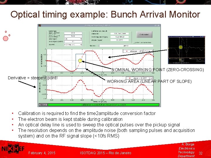
Optical timing example: Bunch Arrival Monitor NOMINAL WORKING POINT (ZERO-CROSSING) Derivative = steepest point! WORKING AREA (LINEAR PART OF SLOPE) • Calibration is required to find the time 2 amplitude conversion factor • The electron beam is kept stable during calibration A. Borga • An optical delay line is used to sweep the optical pulses over the pickup signal Electronics • The resolution depends on the amplitude noise (both sampling pulses and acquisition Technolog system) and on the RF signal slope (<10 fs RMS) y Department February 4, 2015 ISOTDAQ 2015 – Rio de Janeiro A. Borga Electronics Technology Department 32
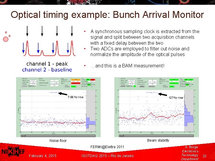
Optical timing example: Bunch Arrival Monitor • • • A synchronous sampling clock is extracted from the signal and split between two acquisition channels with a fixed delay between the two Two ADCs are employed to filter out noise and normalize the amplitude of the optical pulses …and this is a BAM measurement! 7. 66 fs rms A. Borga Electronics. Technolog y Department 127 fs rms Beam stability Noise floor FERMI@Elettra 2011 February 4, 2015 ISOTDAQ 2015 – Rio de Janeiro A. Borga Electronics Technology Department 33
Takeaway thoughts Light… has a bright side! Application of optical links are broad and varied It has a fundamental importance and interest in both the physics (of the phenomena) and engineering (of the equipment) There are lots of Nobel prize winners for optics related discoveries! Think hard! Acknowledgments: A. Borga Electronics. Technolog y Department Peter Jansweijer (Nikhef), Fabio Rossi (FERMI@Elettra) February 4, 2015 ISOTDAQ 2015 – Rio de Janeiro A. Borga Electronics Technology Department 34
- Slides: 34