Optical Fiber Optical Fiber n A thin 2

Optical Fiber
 flexible strand of glass or plastic")
Optical Fiber n A thin (2 -125 m) flexible strand of glass or plastic q q Light entering at one end travels confined within the fiber until it leaves it at the other end As fiber bends around corners, the light remains within the fiber through multiple internal reflections Lowest losses (attenuation) with Quali ultra pure fused silica glass… ) ty (Loss Diffic , Cost, n o i t a ulty o ttenu f Han but expensive and more difficult to dlin. A g manufacture Reasonable losses with multi. Pure Multi. Plastic Glass component glass and with plastic Glass

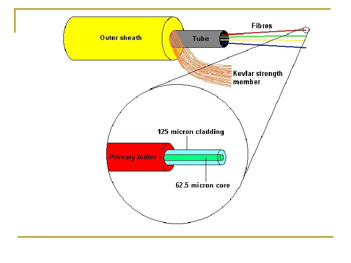
Optical Fiber: Construction n An optical fiber consists of three main parts q Core n q Cladding n n q A narrow cylindrical strand of glass/plastic, with refractive index n 1 A tube surrounding each core, with refractive index n 2 The core must have a higher refractive index than the cladding to keep the light beam trapped inside: n 1 > n 2 Protective outer jacket n Protects against moisture, crushing Individual Fibers: (Each having its core & Cladding) Single Fiber Cable Multiple Fiber Cable Important: Each core surrounded by a cladding

Reflection and Refraction Increasing Incidence angle, 1 rarer n 2 denser n 1 n At a n 1 > n 2 2 Angles With the Normal v 2 = c/n 2 1 2 boundary between a denser (n 1) and a rarer (n 2) critical 1 v = c/n 1 medium, n 1 > 1 n 2 (e. g. water-air, optical fiber core. Total internal Critical angle Refraction cladding) a ray of light will be refracted or reflected reflection depending on the incidence angle

Optical Fiber Refraction at boundary for i < critical. Escaping light is absorbed in jacket Rarer Denser Rarer n 1 > n 2 n 1 Total Internal Reflection at i core-cladding boundary for i > critical
 then there is no")
Total Internal Reflection • As 1 increases (or 1 decreases) then there is no reflection • The incident angle 1 = c = Critical Angle • Beyond the critical angle, light ray becomes totally internally reflected When 1 = 90 o (or c = 0 o) n 1 sin 1 = n 2 Thus the critical angle n 1 > n 2 1 c n 1 > n 2 1< c n 1 n 2 1 1> c n 1

Ray Propagation in Fibre - Bound Rays > c, > max 5 c 3 2 1 4 Core n 1 Air (no =1) Cladding n 2 From Snell’s Law: n 0 sin = n 1 sin (90 - ) Thus, n 0 sin max = n 1 cos c = when = c max a

Ray Propagation in Fibre - contd. Or n 0 sin max = n 1 (1 - sin 2 c)0. 5 Since Then NA determines the light gathering capabilities of the fibre

Ray Propagation in Fibre - contd. Therefore n 0 sin max = NA Fibre acceptance angle Thus 0. 14< NA < 1

Attenuation in Guided Media Larger Frequency

Optical Fiber - Benefits n Greater capacity q q q n Lower/more uniform* attenuation (Figure) q q n Fiber: 100’s of Gbps over 10’s of Kms Cable: 100’s of Mbps over 1’s of Kms Twisted pair: 100’s of Mbps over 10’s of meters An order of magnitude lower Relatively constant over a larger range of frequencies* Electromagnetic isolation q q Not affected by external EM fields: n No interference, impulse noise, crosstalk Does not radiate: n Not a source of interference n Difficult to tap (data security) * With careful selection of operating band

Optical Fiber – Benefits, Contd. n Greater repeater spacing: Lower cost, Fewer Units q q n Fiber: 10 -100’s of Kms Cable, Twisted pair: 1’s Kms Smaller size and weight: q An order of magnitude thinner for same capacity n n n Useful in cramped places Reduced cost of digging in populated areas Reduced cost of support structures

Optical Fiber - Applications n Long-haul trunks q Telephone traffic over long routes between cities, and undersea: n n n Metropolitan trunks q Joining exchanges inside large cities: n n City Joining exchanges of towns and villages: n 40 -160 km, Up to 5, 000 voice channels Subscriber loops q City Joining subscribers to exchange: n n 12 km, Up to 100, 000 voice channels Exchange Rural exchange trunks q n Fiber & Microwave now replacing coaxial cable 1500 km, Up to 60, 000 voice channels Fiber replacing TP, allowing all types of data LANs, Main Exchange

Optical Fiber - Transmission Characteristics n Acts as a wave guide for light (1014 to 1015 Hz) q n Covers portions of infrared and visible spectrum Transmission Modes: Multimode Single Mode Step Index Graded Index

Modes in Fibre n A fiber can support: q q n many modes (multi-mode fibre). a single mode (single mode fiber). The number of modes supported in a fiber is determined by the indices, operating wavelength and the diameter of the core, given as. or n n V<2. 405 corresponds to a single mode fiber. By reducing the radius of the fiber, V goes down, and it becomes impossible to reach a point when only a single mode can be supported.
 Step index: • Multi-mode")
Types of Fibre There are two main fibre types: (1) Step index: • Multi-mode • Single mode (2) Graded index multi-mode Total number of guided modes M for multi-mode fibres: Multi-mode SI Multi-mode GI

Step-index Multi-mode Fibre Input pulse 120 -400 m 50 -200 m Output pulse n 1 =1. 48 -1. 5 n 2 = 1. 46 100 ns/km Advantages: • Allows the use of non-coherent optical light source, e. g. LED's • Facilitates connecting together similar fibres • Imposes lower tolerance requirements on fibre connectors. • Cost effective Disadvantages: • Suffer from dispersion (i. e. low bandwidth (a few MHz) • High power loss

Graded-index Multi-mode Fibre 50 -100 m Input pulse 120 -140 m n 2 n 1 Output pulse 1 ns/km Advantages: • Allows the use of non-coherent optical light source, e. g. LED's • Facilitates connecting together similar fibres • Imposes lower tolerance requirements on fibre connectors. • Reduced dispersion compared with STMMF Disadvantages: • Lower bandwidth compared with STSMF • High power loss compared with the STSMF

Step-index Single-mode Fibre Input pulse 100 -120 m 8 -12 m Output pulse n 1 =1. 48 -1. 5 n 2 = 1. 46 5 ps/km Advantages: • Only one mode is allowed due to diffraction/interference effects. • Allows the use high power laser source • Facilitates fusion splicing similar fibres • Low dispersion, therefore high bandwidth (a few GHz). • Low loss (0. 1 d. B/km) Disadvantages: • Cost

Optical Fiber – Transmission modes n n Spread of received light pulse in time (dispersion) is bad: q Causes inter-symbol interference bit errors (similar to delay distortion) q Limits usable data rate and usable transmission distance Caused by propagation through multiple reflections at different angles of incidence Dispersion increases with: q Larger distance traveled q Thicker fibers with step index q Less focused sources Can be reduced by: q Limiting the distance q Thinner fibers and a highly focused light source Single mode (in the limit): High data rates, very long distances q Or Graded-index multimode thicker fibers: The half-way (lower cost) solution

Optical Fiber Transmission System– Light Source + Fiber + Light Detector Light Sources n Light Emitting Diode (LED) q q n Incoherent light- More dispersion Lower data rates Low cost Wider operating temp range Longer life Injection Laser Diode (ILD) q q q Coherent light- Less dispersion Higher data rate More efficient Faster switching Higher data rate
 n n n A form of FDM")
Optical Fiber – Wavelength Division Multiplexing (WDM) n n n A form of FDM (Channels sharing the medium by occupying different frequency bands) Multiple light beams at different light frequencies (wavelengths) transmitted on the same fiber Each beam forms a separate communication channel Separated at destination by filters Example: 256 channels @ 40 Gbps each 10 Tbps total data rate WDM
 in the Infrared (IR) region n Band")
Optical Fiber – Four Transmission bands (windows) in the Infrared (IR) region n Band selection is a system decision based on: q q q Attenuation of the fiber Properties of the light sources Properties of the light receivers S C L Bandwidth, THz 33 12 4 7 Note: l in fiber = v/f = (c/n)/f = (c/f)/n = l in vacuum/n i. e. l in fiber < l in vacuum
- Slides: 24