
Operation Concepts Definition Document OCDD Chip Kobulnicky University
Operation Concepts Definition Document (OCDD) Chip Kobulnicky University of Wisconsin Oct 17, 2001 SALT PFIS Preliminary Design Review 1
Operational Mode Description • Operational modes are fully characterized by the configuration of 4 primary subsystems (“basis vectors” in 4 -D) which describe the dataset being acquired. – – Focal Plane Elements (spatial) Dispersive Elements (spectral) Polarizing Elements (polarization) Detector (time) Oct 17, 2001 SALT PFIS Preliminary Design Review 2
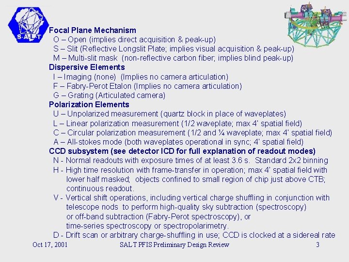
Focal Plane Mechanism O – Open (implies direct acquisition & peak-up) S – Slit (Reflective Longslit Plate; implies visual acquisition & peak-up) M – Multi-slit mask (non-reflective carbon fiber; implies blind peak-up) Dispersive Elements I – Imaging (none) (Implies no camera articulation) F – Fabry-Perot Etalon (Implies no camera articulation) G – Grating (Articulated camera) Polarization Elements U – Unpolarized measurement (quartz block in place of waveplates) L – Linear polarization measurement (1/2 waveplate; max 4’ spatial field) C – Circular polarization measurement (1/2 and ¼ waveplate; max 4’ spatial field) A – All-stokes mode (both waveplates operational in sync; 4’ spatial field) CCD subsystem (see detector ICD for full explanation of readout modes) N - Normal readouts with exposure times of at least 3. 6 s. Standard 2 x 2 binning H - High time resolution with frame-transfer in operation; max 4’ spatial field with lower half masked; objects confined to small region of chip just above CTB; continuous readout. V - Vertical shift operations, including vertical charge shuffling in conjunction with telescope nods to perform high-quality sky subtraction (spectroscopy) or off-band subtraction (Fabry-Perot spectroscopy), or time-series spectroscopy or spectropolarimetry. D - Drift scan or arbitrary charge-shuffling in use; CCD is clocked at a sidereal rate Oct 17, 2001 SALT PFIS Preliminary Design Review 3
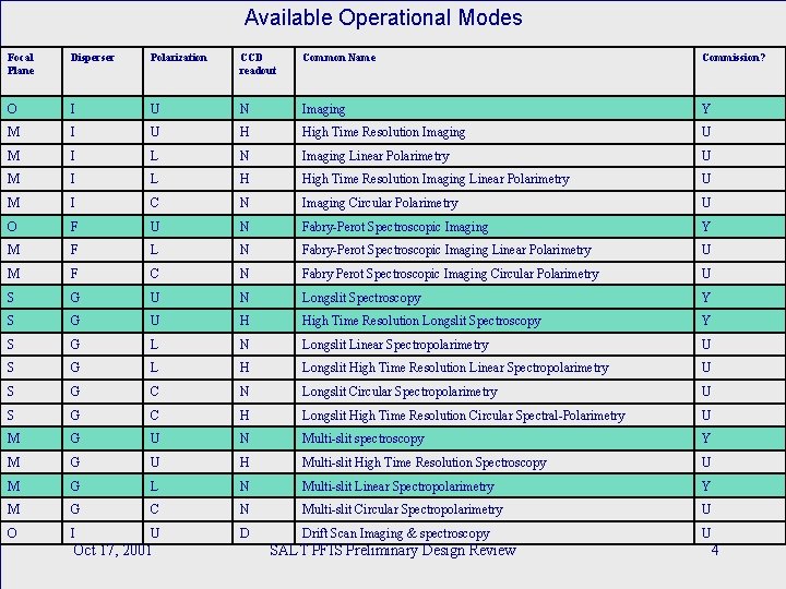
Available Operational Modes Focal Plane Disperser Polarization CCD readout Common Name Commission? O I U N Imaging Y M I U H High Time Resolution Imaging U M I L N Imaging Linear Polarimetry U M I L H High Time Resolution Imaging Linear Polarimetry U M I C N Imaging Circular Polarimetry U O F U N Fabry-Perot Spectroscopic Imaging Y M F L N Fabry-Perot Spectroscopic Imaging Linear Polarimetry U M F C N Fabry Perot Spectroscopic Imaging Circular Polarimetry U S G U N Longslit Spectroscopy Y S G U H High Time Resolution Longslit Spectroscopy Y S G L N Longslit Linear Spectropolarimetry U S G L H Longslit High Time Resolution Linear Spectropolarimetry U S G C N Longslit Circular Spectropolarimetry U S G C H Longslit High Time Resolution Circular Spectral-Polarimetry U M G U N Multi-slit spectroscopy Y M G U H Multi-slit High Time Resolution Spectroscopy U M G L N Multi-slit Linear Spectropolarimetry Y M G C N Multi-slit Circular Spectropolarimetry U O I U D Drift Scan Imaging & spectroscopy U Oct 17, 2001 SALT PFIS Preliminary Design Review 4
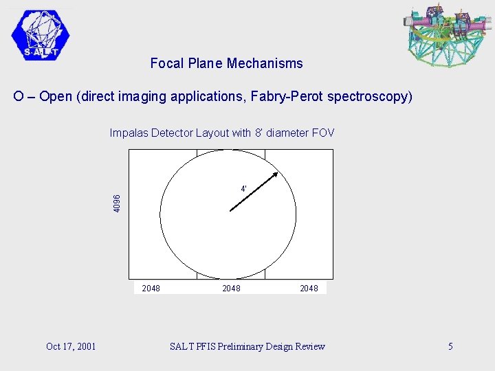
Focal Plane Mechanisms O – Open (direct imaging applications, Fabry-Perot spectroscopy) Impalas Detector Layout with 8’ diameter FOV 4096 4’ 2048 Oct 17, 2001 2048 SALT PFIS Preliminary Design Review 5
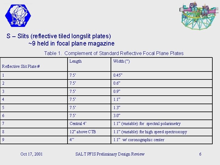
S – Slits (reflective tiled longslit plates) ~9 held in focal plane magazine Table 1. Complement of Standard Reflective Focal Plane Plates Length Width (“) 1 7. 5’ 0. 45” 2 7. 5’ 0. 6” 3 7. 5’ 0. 9” 4 7. 5’ 1. 1” 5 7. 5’ 1. 3” 6 7. 5’ 3. 0” 7 Central 4’ 1. 1” (variable) for spectral polarimetry 8 12” above CTB 1. 1” (variable) for high speed spectroscopy 9 4’’ 1. 1” w/ coronographic center Reflective Slit Plate # Oct 17, 2001 SALT PFIS Preliminary Design Review 6
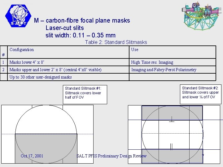
M – carbon-fibre focal plane masks Laser-cut slits slit width: 0. 11 – 0. 35 mm Table 2: Standard Slitmasks Configuration Use 1 Masks lower 4’ x 8’ High Time res. Imaging 2 Masks upper and lower 2’ x 8’ (central 4’x 8’ visible) Imaging and Fabry-Perot Polarimetry # Up to 30 other user-designed masks Standard Slitmask #1: Slitmask covers lower half of FOV Oct 17, 2001 SALT PFIS Preliminary Design Review Standard Slitmask #2: Slitmask covers upper and lower ¼ of FOV 7
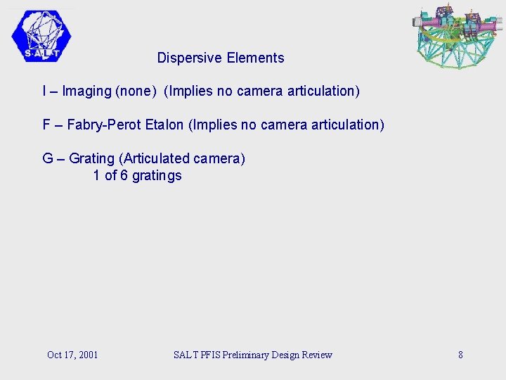
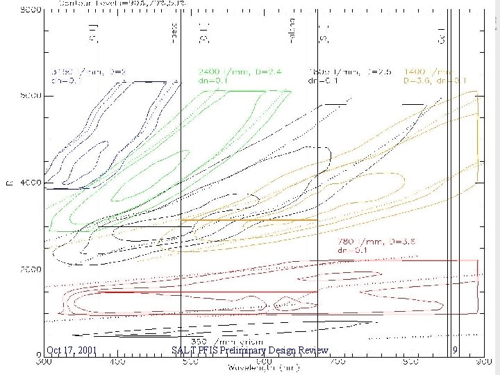
Dispersive Elements I – Imaging (none) (Implies no camera articulation) F – Fabry-Perot Etalon (Implies no camera articulation) G – Grating (Articulated camera) 1 of 6 gratings Oct 17, 2001 SALT PFIS Preliminary Design Review 8
Oct 17, 2001 SALT PFIS Preliminary Design Review 9
Polarizing Elements U – Unpolarized measurements (quartz block in beam) L – Linear polarization (half-waveplate; rotates through 8 positions) C – Circular polarization (half- and quarter-waveplate) A – All-stokes mode (synchronized half- and quarter-waveplate) Oct 17, 2001 SALT PFIS Preliminary Design Review 10
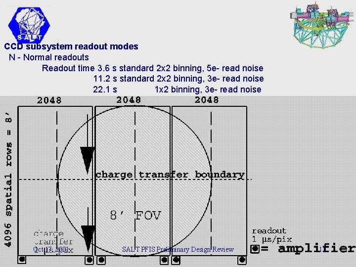
CCD subsystem readout modes N - Normal readouts Readout time 3. 6 s standard 2 x 2 binning, 5 e- read noise 11. 2 s standard 2 x 2 binning, 3 e- read noise 22. 1 s 1 x 2 binning, 3 e- read noise Oct 17, 2001 SALT PFIS Preliminary Design Review 11
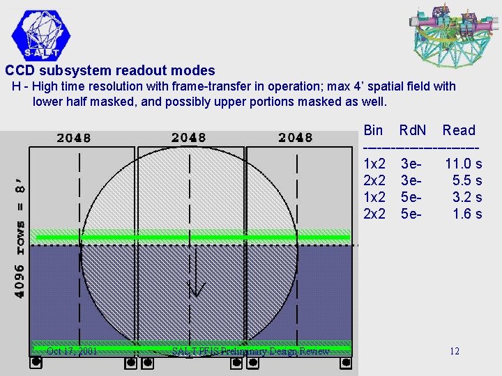
CCD subsystem readout modes H - High time resolution with frame-transfer in operation; max 4’ spatial field with lower half masked, and possibly upper portions masked as well. Bin Rd. N Read ------------1 x 2 3 e 11. 0 s 2 x 2 3 e 5. 5 s 1 x 2 5 e 3. 2 s 2 x 2 5 e 1. 6 s Oct 17, 2001 SALT PFIS Preliminary Design Review 12
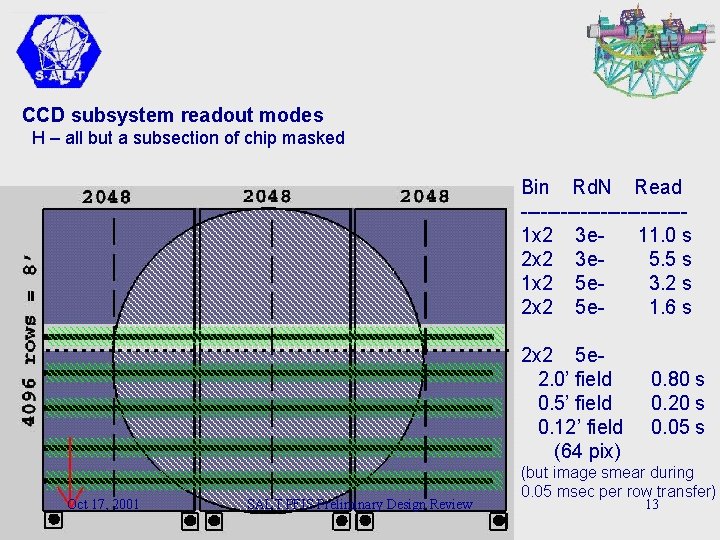
CCD subsystem readout modes H – all but a subsection of chip masked Bin Rd. N Read ------------1 x 2 3 e 11. 0 s 2 x 2 3 e 5. 5 s 1 x 2 5 e 3. 2 s 2 x 2 5 e 1. 6 s 2 x 2 5 e 2. 0’ field 0. 5’ field 0. 12’ field (64 pix) Oct 17, 2001 SALT PFIS Preliminary Design Review 0. 80 s 0. 20 s 0. 05 s (but image smear during 0. 05 msec per row transfer) 13
CCD subsystem readout modes V - Vertical shift operations, including vertical charge shuffling in conjunction with telescope nods to perform high-quality sky subtraction (spectroscopy) or off-band subtraction (Fabry-Perot spectroscopy), or time-series spectroscopy or spectropolarimetry. D - Drift scan or arbitrary charge-shuffling in use; CCD is clocked at a sidereal or other rate Oct 17, 2001 SALT PFIS Preliminary Design Review 14
Example of longslit spectroscopic mode operation Simultaneous! Typical sequence of operation: Setup Telescope & Instrument (LOW OVERHEAD DESIGN GOAL FOR QUEUE MODE) Rotate telescope in Azimuth to correct location (few min; rate-limiting action) Select & insert filter (43 s) Select & insert grating (25 s) Select & insert longslit plate to be used (50 s) Articulate camera to desired position angle (<70 s) Acquire Field/Target Image field w/SALTICAM off reflective slitplate (2’ FOV) Locate desired object and move tracker to place object on slit Do Science Begin tracking/guiding using either guide probes or slit viewer camera Begin exposure Insert cal. lamp & take arc exposure Data Rate: 6154 pixels spectral x 4096 pixels spatial at >3. 6 s total readout time Target acquisition: By guide probe, and using visual peak-up with SALTICAM as slit viewing camera. Tracking During Exposures: By guide probe, or by reflected light from slit viewed by SALTICAM. Oct 17, 2001 SALT PFIS Preliminary Design Review 15
Example of multi-slit (slitmask) spectroscopic mode Peak-up performed In spectral mode Simultaneous Setup Telescope & Instrument Rotate telescope in Azimuth to correct location (few min; rate-limiting step) Select & insert filter (43 s) Select & insert grating (25) Select & insert slitmask to be used (50 s) Articulate camera to desired position angle (<70 s) Acquire Field/target (no view of slit, like nearly all multi-slit spectrographs) Insert SALTICAM fold mirror Image field with acquisition camera (SALTICAM) to locate alignment stars Perform offset to place alignment stars at proper location on focal plane (blind, but calibrated offsets) Remove fold mirror Perfect alignment by taking a series of exposures while performing a patterned dither on sky Location of maximum signal is used as final alignment position (0. 5 s x 9) [ fallback acquisition plan is direct imaging through unarticulated camera] Do Science Begin tracking/guiding using guide probes Begin science exposure Insert diffuser/cal lamp and do arc exposures Data Rate: 6154 pixels spectral x 4096 pixels spatial at >3. 6 s total readout time Target acquisition: By SALTICAM, guide probe, and dithered exposure peak-up Tracking During Exposures: By guide probe Oct 17, 2001 SALT PFIS Preliminary Design Review 16
Instrument Commissioning Plan • Let science drive commissioning Goal: 6 science programs corresponding to each major instrument mode • Start with simplest modes (i. e. , imaging) • Fully commission all “basic” modes • Leave specialized modes to users for shared-risk basis • Reduction Software: standard community tools Oct 17, 2001 SALT PFIS Preliminary Design Review 17
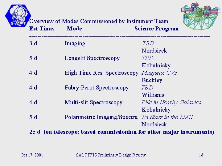
Overview of Modes Commissioned by Instrument Team Est Time. Mode Science Program --------------------------------------------3 d Imaging TBD Nordsieck 5 d Longslit Spectroscopy TBD Kobulnicky 4 d High Time Res. Spectroscopy Magnetic CVs Buckley 4 d Fabry-Perot Spectroscopy TBD Williams 4 d Multi-slit Spectroscopy PNe in Nearby Galaxies Kobulnicky 5 d Polarimetric Imaging/Spectra Be Stars in the LMC Nordsieck 25 d (on telescope; based commissioning for other major instruments) Oct 17, 2001 SALT PFIS Preliminary Design Review 18
Other possible user-commissioned modes (extensions of team-commissioned modes) High Time Resolution Spectral-Polarimetry Fabry-Perot Spectral-Polarimetry Circular polarimetry Circular Spectral-Polarimetry All-stokes Polarimetry High Time Resolution Multi-slit Spectral Polarimetry Shift+nod high-precision spectroscopy Drift scan imaging Oct 17, 2001 SALT PFIS Preliminary Design Review 19
Commissioning tasks not requiring all mirror segments - acquisition strategies - software interfaces - focus, optical distortion, vignetting tests - wavelength calibration & stability - tracking & guiding stability Commissioning tasks requiring all mirror segments - instrumental polarization calibrations - total sensitivity calibrations - final flatfield calibrations & variability - other aspects sensitive to pupil illumination Oct 17, 2001 SALT PFIS Preliminary Design Review 20
Calibration Issues Wavelength: He, Ne, Ar, Cu lamps fed to diffuser before moving baffle Flatfields: Continuum lamps fed to diffuser before moving baffle Flats taken next morning by re-creating actual science tracks w/baffle Observing scripts stored for easy reproduction (only a subset of spectrophotometric observations will need this precision) Observatory “superflats” created periodically in standard configurations -> enable differential flats taken on nightly basis Stray/scattered light? TBD during commissioning Oct 17, 2001 SALT PFIS Preliminary Design Review 21
Oct 17, 2001 SALT PFIS Preliminary Design Review 22
Oct 17, 2001 SALT PFIS Preliminary Design Review 23
Oct 17, 2001 SALT PFIS Preliminary Design Review 24
- Slides: 24