
ONS 15454 MSTP DWDM Networking Primer October 2003
ONS 15454 MSTP DWDM Networking Primer October 2003 © 2003, Cisco Systems, Inc. All rights reserved.
Agenda • Introduction • Optical Fundamentals • Dense Wavelength Division Multiplexing (DWDM) © 2003, Cisco Systems, Inc. All rights reserved.
Optical Fundamentals © 2003, Cisco Systems, Inc. All rights reserved.
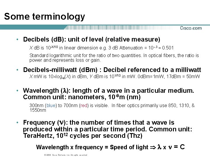
Some terminology • Decibels (d. B): unit of level (relative measure) X d. B is 10 -X/10 in linear dimension e. g. 3 d. B Attenuation = 10 -. 3 = 0. 501 Standard logarithmic unit for the ratio of two quantities. In optical fibers, the ratio is power and represents loss or gain. • Decibels-milliwatt (d. Bm) : Decibel referenced to a milliwatt X m. W is 10 log 10(X) in d. Bm, Y d. Bm is 10 Y/10 in m. W. 0 d. Bm=1 m. W, 17 d. Bm = 50 m. W • Wavelength ( ): length of a wave in a particular medium. Common unit: nanometers, 10 -9 m (nm) 300 nm (blue) to 700 nm (red) is visible. In fiber optics primarily use 850, 1310, & 1550 nm • Frequency ( ): the number of times that a wave is produced within a particular time period. Common unit: Tera. Hertz, 1012 cycles per second (Thz) Wavelength x frequency = Speed of light x © 2003, Cisco Systems, Inc. All rights reserved. =C
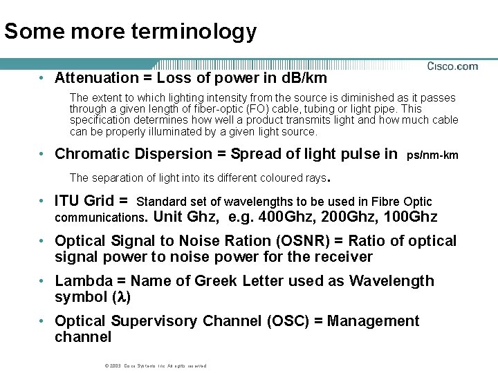
Some more terminology • Attenuation = Loss of power in d. B/km The extent to which lighting intensity from the source is diminished as it passes through a given length of fiber-optic (FO) cable, tubing or light pipe. This specification determines how well a product transmits light and how much cable can be properly illuminated by a given light source. • Chromatic Dispersion = Spread of light pulse in ps/nm-km The separation of light into its different coloured rays. • ITU Grid = Standard set of wavelengths to be used in Fibre Optic communications. Unit Ghz, e. g. 400 Ghz, 200 Ghz, 100 Ghz • Optical Signal to Noise Ration (OSNR) = Ratio of optical signal power to noise power for the receiver • Lambda = Name of Greek Letter used as Wavelength symbol ( ) • Optical Supervisory Channel (OSC) = Management channel © 2003, Cisco Systems, Inc. All rights reserved.

d. B versus d. Bm • d. Bm used for output power and receive sensitivity (Absolute Value) • d. B used for power gain or loss (Relative Value) © 2003, Cisco Systems, Inc. All rights reserved.
Bit Error Rate ( BER) • BER is a key objective of the Optical System Design • Goal is to get from Tx to Rx with a BER < BER threshold of the Rx • BER thresholds are on Data sheets • Typical minimum acceptable rate is 10 -12 © 2003, Cisco Systems, Inc. All rights reserved.
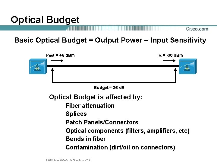
Optical Budget Basic Optical Budget = Output Power – Input Sensitivity Pout = +6 d. Bm R = -30 d. Bm Budget = 36 d. B Optical Budget is affected by: Fiber attenuation Splices Patch Panels/Connectors Optical components (filters, amplifiers, etc) Bends in fiber Contamination (dirt/oil on connectors) © 2003, Cisco Systems, Inc. All rights reserved.
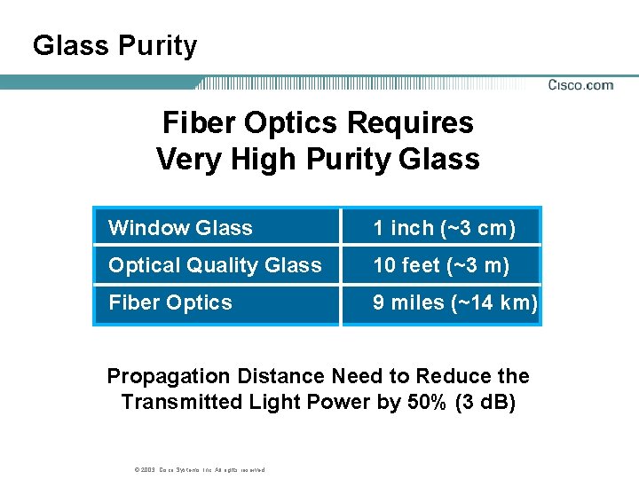
Glass Purity Fiber Optics Requires Very High Purity Glass Window Glass 1 inch (~3 cm) Optical Quality Glass 10 feet (~3 m) Fiber Optics 9 miles (~14 km) Propagation Distance Need to Reduce the Transmitted Light Power by 50% (3 d. B) © 2003, Cisco Systems, Inc. All rights reserved.
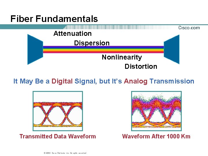
Fiber Fundamentals Attenuation Dispersion Nonlinearity Distortion It May Be a Digital Signal, but It’s Analog Transmission Transmitted Data Waveform © 2003, Cisco Systems, Inc. All rights reserved. Waveform After 1000 Km
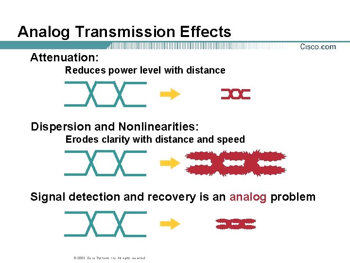
Analog Transmission Effects Attenuation: Reduces power level with distance Dispersion and Nonlinearities: Erodes clarity with distance and speed Signal detection and recovery is an analog problem © 2003, Cisco Systems, Inc. All rights reserved.
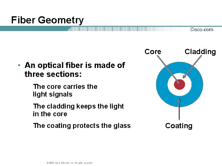
Fiber Geometry Core Cladding • An optical fiber is made of three sections: The core carries the light signals The cladding keeps the light in the core The coating protects the glass © 2003, Cisco Systems, Inc. All rights reserved. Coating
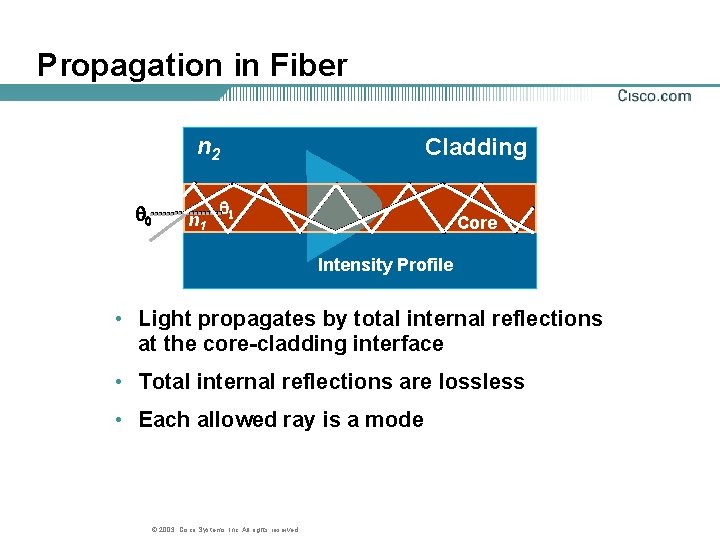
Propagation in Fiber n 2 q 0 n 1 Cladding q 1 Core Intensity Profile • Light propagates by total internal reflections at the core-cladding interface • Total internal reflections are lossless • Each allowed ray is a mode © 2003, Cisco Systems, Inc. All rights reserved.
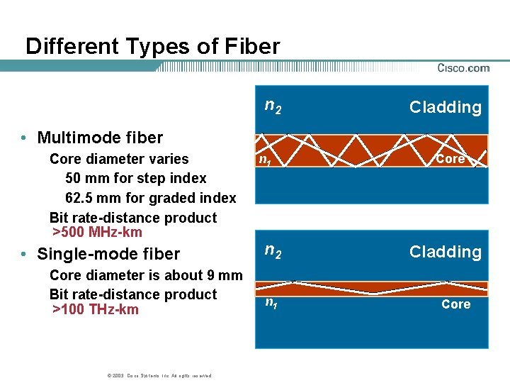
Different Types of Fiber n 2 Cladding • Multimode fiber Core diameter varies 50 mm for step index 62. 5 mm for graded index Bit rate-distance product >500 MHz-km • Single-mode fiber Core diameter is about 9 mm Bit rate-distance product >100 THz-km © 2003, Cisco Systems, Inc. All rights reserved. n 1 n 2 n 1 Core Cladding Core
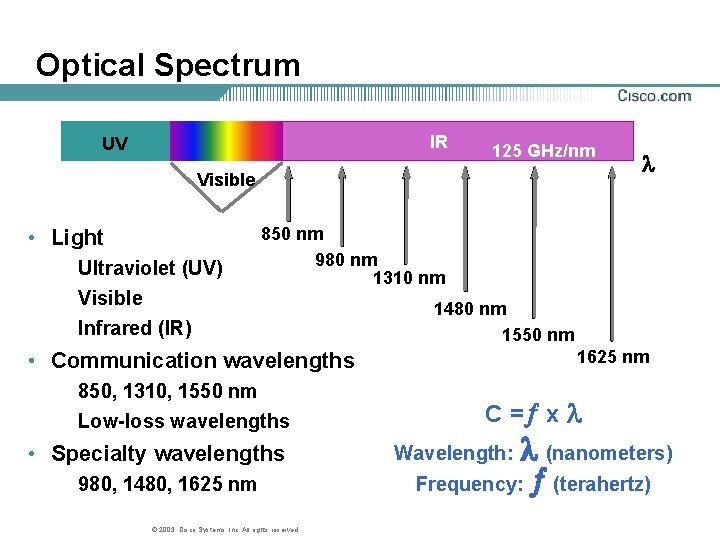
Optical Spectrum IR UV 125 GHz/nm Visible • Light Ultraviolet (UV) Visible Infrared (IR) 850 nm 980 nm 1310 nm 1480 nm 1550 nm 1625 nm • Communication wavelengths 850, 1310, 1550 nm Low-loss wavelengths • Specialty wavelengths 980, 1480, 1625 nm © 2003, Cisco Systems, Inc. All rights reserved. C =¦ x (nanometers) Frequency: ¦ (terahertz) Wavelength:
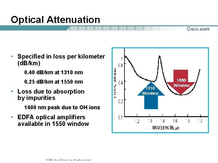
Optical Attenuation • Specified in loss per kilometer (d. B/km) 0. 40 d. B/km at 1310 nm 0. 25 d. B/km at 1550 nm • Loss due to absorption by impurities 1400 nm peak due to OH ions • EDFA optical amplifiers available in 1550 window © 2003, Cisco Systems, Inc. All rights reserved. 1310 Window 1550 Window
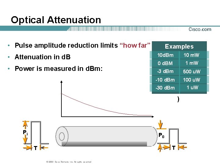
Optical Attenuation • Pulse amplitude reduction limits “how far” • Attenuation in d. B • Power is measured in d. Bm: Examples 10 d. Bm 10 m. W 0 d. BM 1 m. W -3 d. Bm 500 u. W -10 d. Bm 100 u. W -30 d. Bm 1 u. W ) Pi P 0 T T © 2003, Cisco Systems, Inc. All rights reserved.
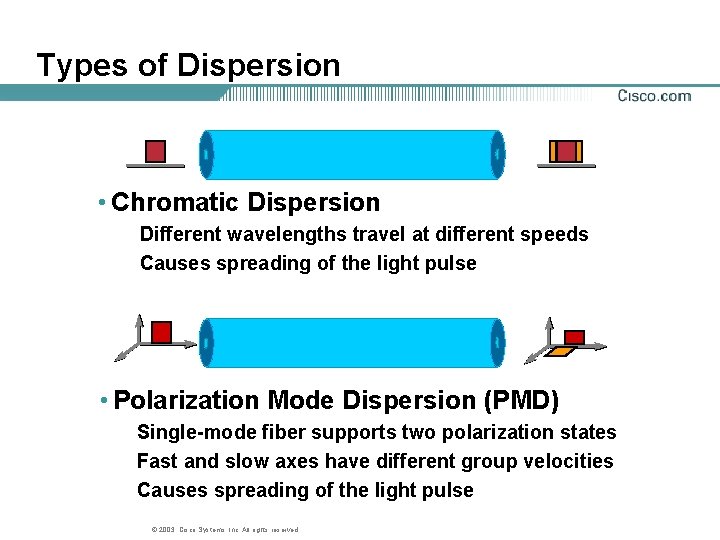
Types of Dispersion • Chromatic Dispersion Different wavelengths travel at different speeds Causes spreading of the light pulse • Polarization Mode Dispersion (PMD) Single-mode fiber supports two polarization states Fast and slow axes have different group velocities Causes spreading of the light pulse © 2003, Cisco Systems, Inc. All rights reserved.
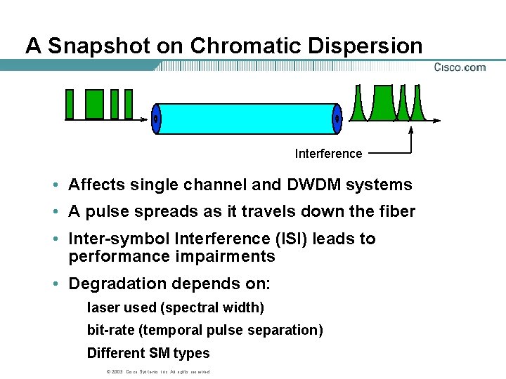
A Snapshot on Chromatic Dispersion Interference • Affects single channel and DWDM systems • A pulse spreads as it travels down the fiber • Inter-symbol Interference (ISI) leads to performance impairments • Degradation depends on: laser used (spectral width) bit-rate (temporal pulse separation) Different SM types © 2003, Cisco Systems, Inc. All rights reserved.
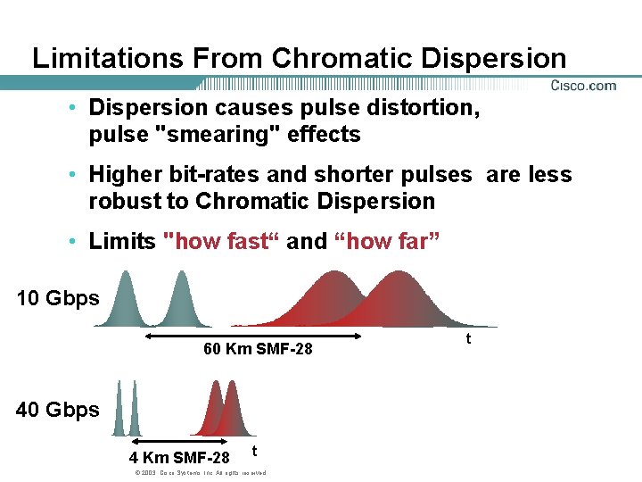
Limitations From Chromatic Dispersion • Dispersion causes pulse distortion, pulse "smearing" effects • Higher bit-rates and shorter pulses are less robust to Chromatic Dispersion • Limits "how fast“ and “how far” 10 Gbps 60 Km SMF-28 40 Gbps 4 Km SMF-28 t © 2003, Cisco Systems, Inc. All rights reserved. t
Combating Chromatic Dispersion • Use DSF and NZDSF fibers (G. 653 & G. 655) • Dispersion Compensating Fiber • Transmitters with narrow spectral width © 2003, Cisco Systems, Inc. All rights reserved.
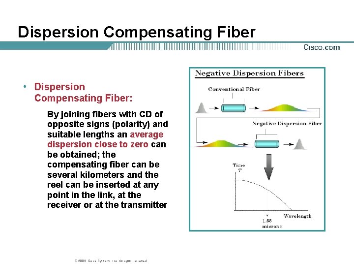
Dispersion Compensating Fiber • Dispersion Compensating Fiber: By joining fibers with CD of opposite signs (polarity) and suitable lengths an average dispersion close to zero can be obtained; the compensating fiber can be several kilometers and the reel can be inserted at any point in the link, at the receiver or at the transmitter © 2003, Cisco Systems, Inc. All rights reserved.
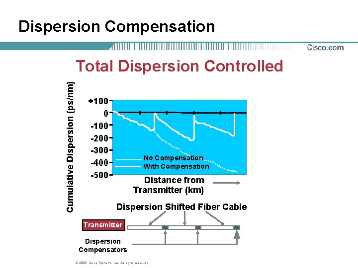
Dispersion Compensation Cumulative Dispersion (ps/nm) Total Dispersion Controlled +100 0 -100 -200 -300 -400 -500 No Compensation With Compensation Distance from Transmitter (km) Dispersion Shifted Fiber Cable Transmitter Dispersion Compensators © 2003, Cisco Systems, Inc. All rights reserved.
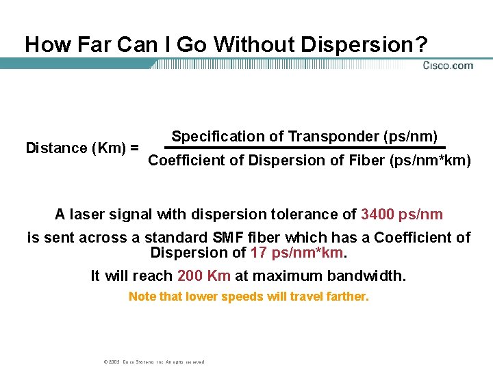
How Far Can I Go Without Dispersion? Distance (Km) = Specification of Transponder (ps/nm) Coefficient of Dispersion of Fiber (ps/nm*km) A laser signal with dispersion tolerance of 3400 ps/nm is sent across a standard SMF fiber which has a Coefficient of Dispersion of 17 ps/nm*km. It will reach 200 Km at maximum bandwidth. Note that lower speeds will travel farther. © 2003, Cisco Systems, Inc. All rights reserved.
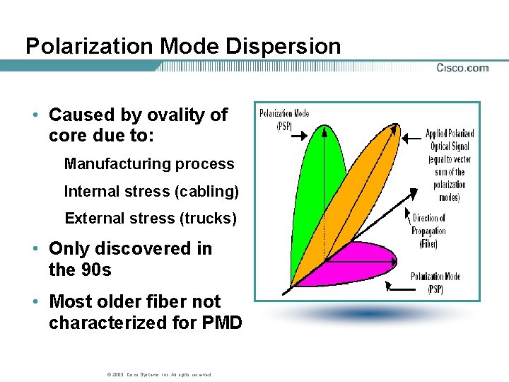
Polarization Mode Dispersion • Caused by ovality of core due to: Manufacturing process Internal stress (cabling) External stress (trucks) • Only discovered in the 90 s • Most older fiber not characterized for PMD © 2003, Cisco Systems, Inc. All rights reserved.
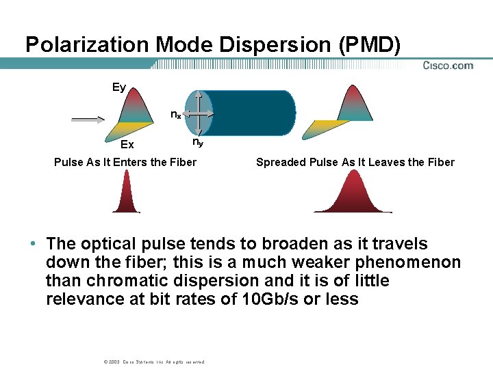
Polarization Mode Dispersion (PMD) Ey nx Ex ny Pulse As It Enters the Fiber Spreaded Pulse As It Leaves the Fiber • The optical pulse tends to broaden as it travels down the fiber; this is a much weaker phenomenon than chromatic dispersion and it is of little relevance at bit rates of 10 Gb/s or less © 2003, Cisco Systems, Inc. All rights reserved.
Combating Polarization Mode Dispersion • Factors contributing to PMD Bit Rate Fiber core symmetry Environmental factors Bends/stress in fiber Imperfections in fiber • Solutions for PMD Improved fibers Regeneration Follow manufacturer’s recommended installation techniques for the fiber cable © 2003, Cisco Systems, Inc. All rights reserved.
Types of Single-Mode Fiber • SMF-28(e) (standard, 1310 nm optimized, G. 652) Most widely deployed so far, introduced in 1986, cheapest • DSF (Dispersion Shifted, G. 653) Intended for single channel operation at 1550 nm • NZDSF (Non-Zero Dispersion Shifted, G. 655) For WDM operation, optimized for 1550 nm region – True. Wave, Free. Light, LEAF, Tera. Light… Latest generation fibers developed in mid 90’s For better performance with high capacity DWDM systems – Metro. Cor, Wide. Light… – Low PMD ULH fibers © 2003, Cisco Systems, Inc. All rights reserved.
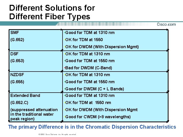
Different Solutions for Different Fiber Types SMF • Good for TDM at 1310 nm (G. 652) • OK for TDM at 1550 • OK for DWDM (With Dispersion Mgmt) DSF • OK for TDM at 1310 nm (G. 653) • Good for TDM at 1550 nm • Bad for DWDM (C-Band) NZDSF • OK for TDM at 1310 nm (G. 655) • Good for TDM at 1550 nm • Good for DWDM (C + L Bands) Extended Band • Good for TDM at 1310 nm (G. 652. C) • OK for TDM at 1550 nm (suppressed attenuation in the traditional water peak region) • OK for DWDM (With Dispersion Mgmt • Good for CWDM (>8 wavelengths) The primary Difference is in the Chromatic Dispersion Characteristics © 2003, Cisco Systems, Inc. All rights reserved.
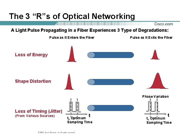
The 3 “R”s of Optical Networking A Light Pulse Propagating in a Fiber Experiences 3 Type of Degradations: Pulse as It Enters the Fiber Pulse as It Exits the Fiber Loss of Energy Shape Distortion Phase Variation Loss of Timing (Jitter) (From Various Sources) t ts Optimum Sampling Time © 2003, Cisco Systems, Inc. All rights reserved. t ts Optimum Sampling Time
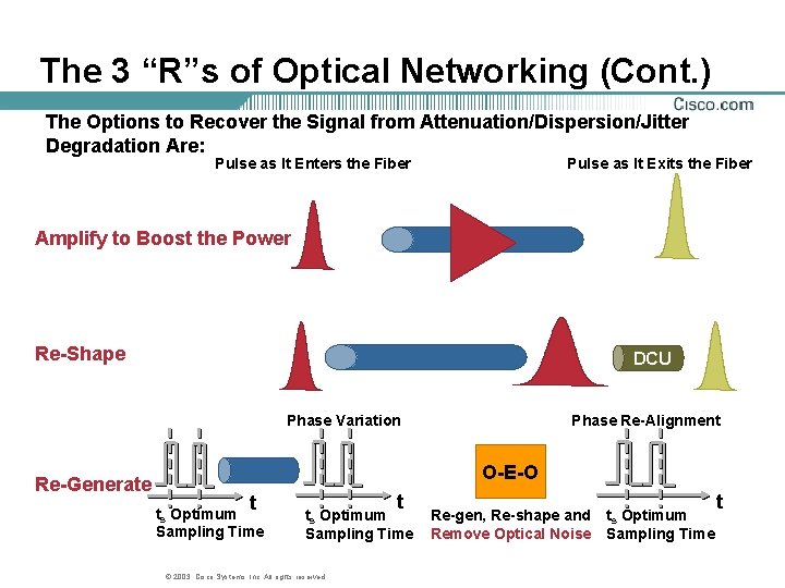
The 3 “R”s of Optical Networking (Cont. ) The Options to Recover the Signal from Attenuation/Dispersion/Jitter Degradation Are: Pulse as It Enters the Fiber Pulse as It Exits the Fiber Amplify to Boost the Power Re-Shape DCU Phase Variation Re-Generate Phase Re-Alignment O-E-O t ts Optimum Sampling Time © 2003, Cisco Systems, Inc. All rights reserved. Re-gen, Re-shape and ts Optimum Remove Optical Noise Sampling Time t
DWDM © 2003, Cisco Systems, Inc. All rights reserved.
Agenda • Introduction • Components • Forward Error Correction • DWDM Design • Summary © 2003, Cisco Systems, Inc. All rights reserved.
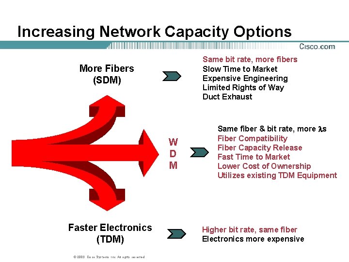
Increasing Network Capacity Options Same bit rate, more fibers Slow Time to Market Expensive Engineering Limited Rights of Way Duct Exhaust More Fibers (SDM) W D M Faster Electronics (TDM) © 2003, Cisco Systems, Inc. All rights reserved. Same fiber & bit rate, more s Fiber Compatibility Fiber Capacity Release Fast Time to Market Lower Cost of Ownership Utilizes existing TDM Equipment Higher bit rate, same fiber Electronics more expensive
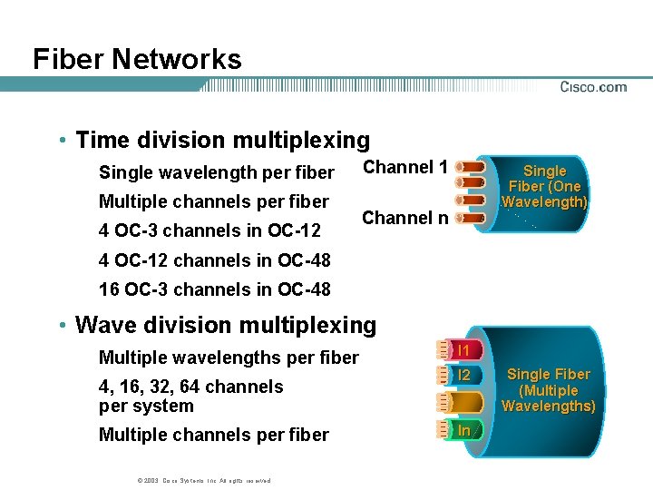
Fiber Networks • Time division multiplexing Single wavelength per fiber Multiple channels per fiber 4 OC-3 channels in OC-12 Channel 1 Single Fiber (One Wavelength) Channel n 4 OC-12 channels in OC-48 16 OC-3 channels in OC-48 • Wave division multiplexing Multiple wavelengths per fiber 4, 16, 32, 64 channels per system Multiple channels per fiber © 2003, Cisco Systems, Inc. All rights reserved. l 1 l 2 ln Single Fiber (Multiple Wavelengths)
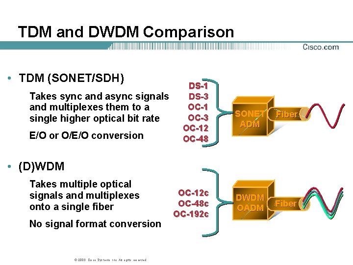
TDM and DWDM Comparison • TDM (SONET/SDH) Takes sync and async signals and multiplexes them to a single higher optical bit rate E/O or O/E/O conversion DS-1 DS-3 OC-1 OC-3 OC-12 OC-48 SONET ADM Fiber • (D)WDM Takes multiple optical signals and multiplexes onto a single fiber No signal format conversion © 2003, Cisco Systems, Inc. All rights reserved. OC-12 c OC-48 c OC-192 c DWDM OADM Fiber
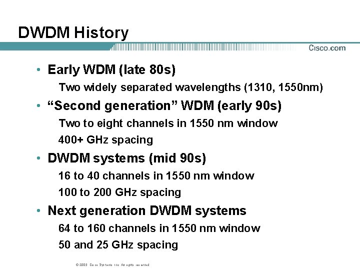
DWDM History • Early WDM (late 80 s) Two widely separated wavelengths (1310, 1550 nm) • “Second generation” WDM (early 90 s) Two to eight channels in 1550 nm window 400+ GHz spacing • DWDM systems (mid 90 s) 16 to 40 channels in 1550 nm window 100 to 200 GHz spacing • Next generation DWDM systems 64 to 160 channels in 1550 nm window 50 and 25 GHz spacing © 2003, Cisco Systems, Inc. All rights reserved.
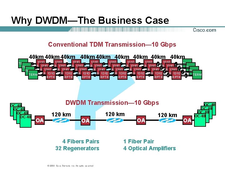
Why DWDM—The Business Case Conventional TDM Transmission— 10 Gbps 40 km 40 km 40 km 1310 1310 TERM 1310 1310 1310 1310 RPTR RPTR RPTR RPTR TERM 1310 1310 RPTR RPTR TERM RPTR RPTR OC-48 DWDM Transmission— 10 Gbps OA 120 km OA 4 Fibers Pairs 32 Regenerators © 2003, Cisco Systems, Inc. All rights reserved. OA 120 km 1 Fiber Pair 4 Optical Amplifiers OA OC-48
Drivers of WDM Economics • Fiber underground/undersea Existing fiber • Conduit rights-of-way Lease or purchase • Digging Time-consuming, labor intensive, license $15, 000 to $90, 000 per Km • 3 R regenerators Space, power, OPS in POP Re-shape, re-time and re-amplify • Simpler network management Delayering, less complexity, less elements © 2003, Cisco Systems, Inc. All rights reserved.
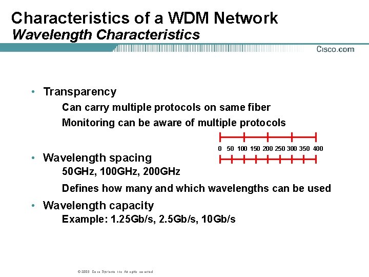
Characteristics of a WDM Network Wavelength Characteristics • Transparency Can carry multiple protocols on same fiber Monitoring can be aware of multiple protocols • Wavelength spacing 0 50 100 150 200 250 300 350 400 50 GHz, 100 GHz, 200 GHz Defines how many and which wavelengths can be used • Wavelength capacity Example: 1. 25 Gb/s, 2. 5 Gb/s, 10 Gb/s © 2003, Cisco Systems, Inc. All rights reserved.
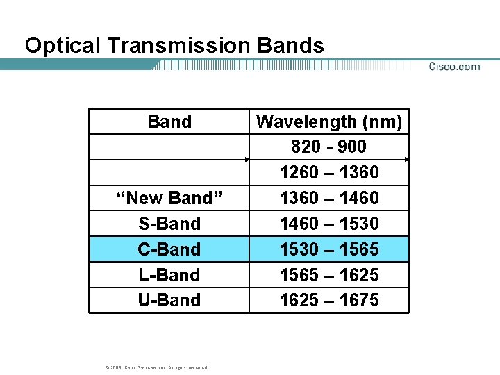
Optical Transmission Bands Band “New Band” S-Band C-Band L-Band U-Band © 2003, Cisco Systems, Inc. All rights reserved. Wavelength (nm) 820 - 900 1260 – 1360 – 1460 – 1530 – 1565 – 1625 – 1675
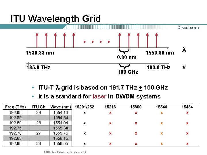
ITU Wavelength Grid 1530. 33 nm 195. 9 THz 0. 80 nm 100 GHz 1553. 86 nm 193. 0 THz • ITU-T grid is based on 191. 7 THz + 100 GHz • It is a standard for laser in DWDM systems © 2003, Cisco Systems, Inc. All rights reserved.
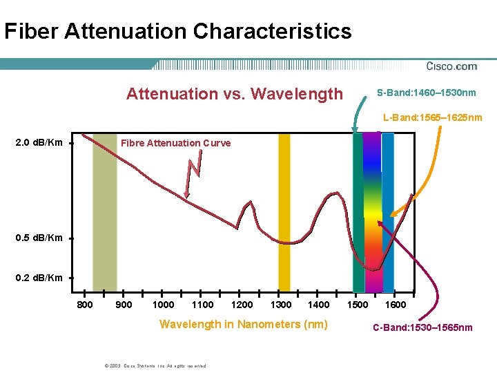
Fiber Attenuation Characteristics Attenuation vs. Wavelength S-Band: 1460– 1530 nm L-Band: 1565– 1625 nm 2. 0 d. B/Km Fibre Attenuation Curve 0. 5 d. B/Km 0. 2 d. B/Km 800 900 1000 1100 1200 1300 1400 Wavelength in Nanometers (nm) © 2003, Cisco Systems, Inc. All rights reserved. 1500 1600 C-Band: 1530– 1565 nm
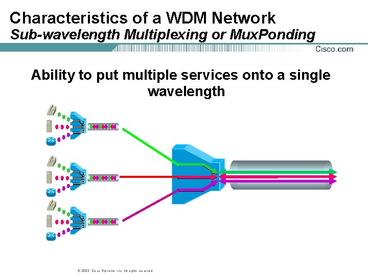
Characteristics of a WDM Network Sub-wavelength Multiplexing or Mux. Ponding Ability to put multiple services onto a single wavelength © 2003, Cisco Systems, Inc. All rights reserved.
Why DWDM? The Technical Argument • DWDM provides enormous amounts of scaleable transmission capacity Unconstrained by speed of available electronics Subject to relaxed dispersion and nonlinearity tolerances Capable of graceful capacity growth © 2003, Cisco Systems, Inc. All rights reserved.
Agenda • Introduction • Components • Forward Error Correction • DWDM Design © 2003, Cisco Systems, Inc. All rights reserved.
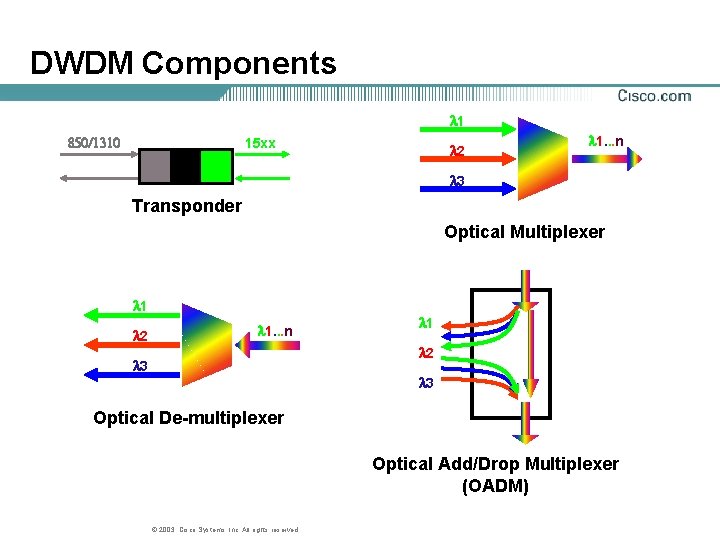
DWDM Components 1 850/1310 15 xx 2 1. . . n 3 Transponder Optical Multiplexer 1 2 1. . . n 1 2 3 3 Optical De-multiplexer Optical Add/Drop Multiplexer (OADM) © 2003, Cisco Systems, Inc. All rights reserved.
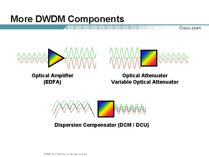
More DWDM Components Optical Amplifier (EDFA) Optical Attenuator Variable Optical Attenuator Dispersion Compensator (DCM / DCU) © 2003, Cisco Systems, Inc. All rights reserved.
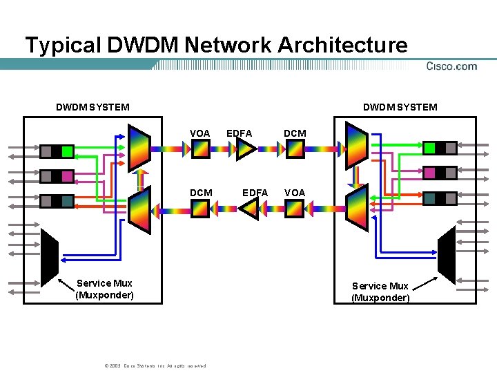
Typical DWDM Network Architecture DWDM SYSTEM VOA DCM Service Mux (Muxponder) © 2003, Cisco Systems, Inc. All rights reserved. EDFA DCM VOA Service Mux (Muxponder)
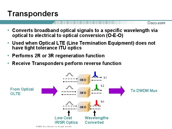
Transponders • Converts broadband optical signals to a specific wavelength via optical to electrical to optical conversion (O-E-O) • Used when Optical LTE (Line Termination Equipment) does not have tight tolerance ITU optics • Performs 2 R or 3 R regeneration function • Receive Transponders perform reverse function OEO l 1 l 2 From Optical OLTE To DWDM Mux OEO ln OEO Low Cost IR/SR Optics © 2003, Cisco Systems, Inc. All rights reserved. Wavelengths Converted
Performance Monitoring • Performance monitoring performed on a per wavelength basis through transponder • No modification of overhead Data transparency is preserved © 2003, Cisco Systems, Inc. All rights reserved.
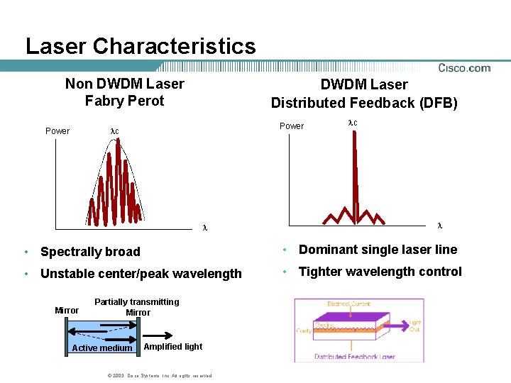
Laser Characteristics Non DWDM Laser Fabry Perot DWDM Laser Distributed Feedback (DFB) Power lc Power l lc l • Spectrally broad • Dominant single laser line • Unstable center/peak wavelength • Tighter wavelength control Mirror Partially transmitting Mirror Active medium Amplified light © 2003, Cisco Systems, Inc. All rights reserved.
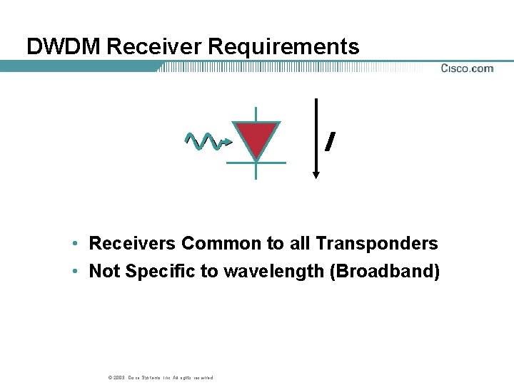
DWDM Receiver Requirements I • Receivers Common to all Transponders • Not Specific to wavelength (Broadband) © 2003, Cisco Systems, Inc. All rights reserved.
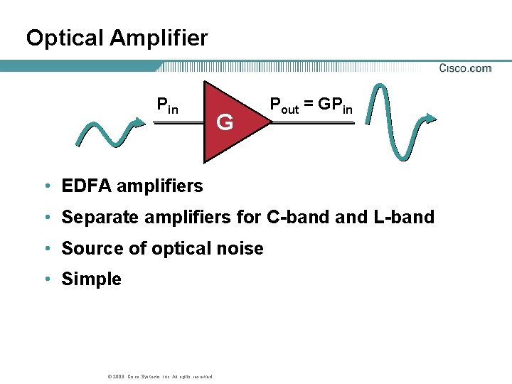
Optical Amplifier Pin G Pout = GPin • EDFA amplifiers • Separate amplifiers for C-band L-band • Source of optical noise • Simple © 2003, Cisco Systems, Inc. All rights reserved.
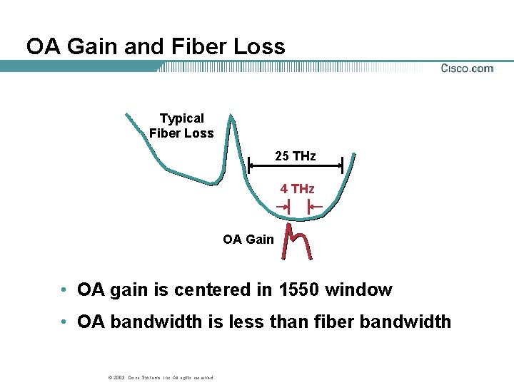
OA Gain and Fiber Loss Typical Fiber Loss 25 THz 4 THz OA Gain • OA gain is centered in 1550 window • OA bandwidth is less than fiber bandwidth © 2003, Cisco Systems, Inc. All rights reserved.
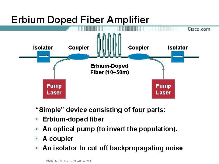
Erbium Doped Fiber Amplifier Isolator Coupler Isolator Erbium-Doped Fiber (10– 50 m) Pump Laser “Simple” device consisting of four parts: • Erbium-doped fiber • An optical pump (to invert the population). • A coupler • An isolator to cut off backpropagating noise © 2003, Cisco Systems, Inc. All rights reserved.
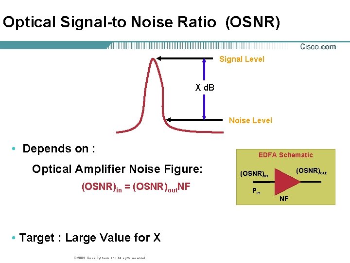
Optical Signal-to Noise Ratio (OSNR) Signal Level X d. B Noise Level • Depends on : Optical Amplifier Noise Figure: (OSNR)in = (OSNR)out. NF • Target : Large Value for X © 2003, Cisco Systems, Inc. All rights reserved. EDFA Schematic (OSNR)out (OSNR)in Pin NF
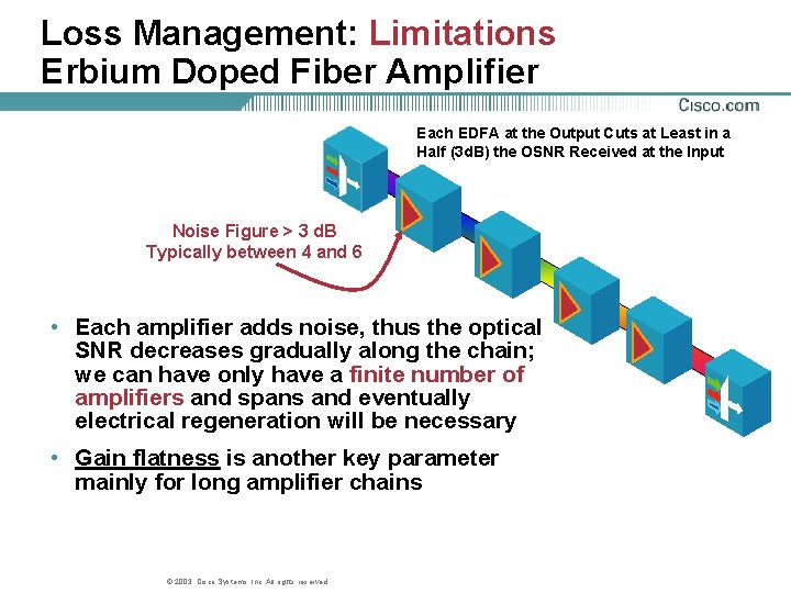
Loss Management: Limitations Erbium Doped Fiber Amplifier Each EDFA at the Output Cuts at Least in a Half (3 d. B) the OSNR Received at the Input Noise Figure > 3 d. B Typically between 4 and 6 • Each amplifier adds noise, thus the optical SNR decreases gradually along the chain; we can have only have a finite number of amplifiers and spans and eventually electrical regeneration will be necessary • Gain flatness is another key parameter mainly for long amplifier chains © 2003, Cisco Systems, Inc. All rights reserved.
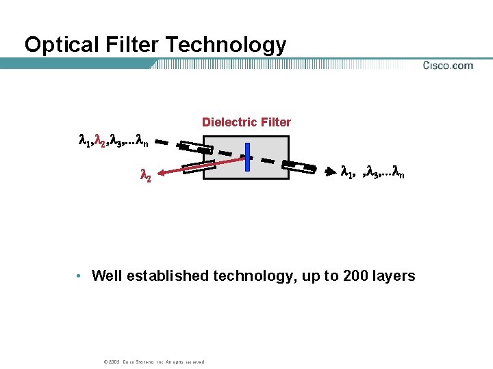
Optical Filter Technology Dielectric Filter 1, 2, 3, . . . n 2 1, , 3, . . . n • Well established technology, up to 200 layers © 2003, Cisco Systems, Inc. All rights reserved.
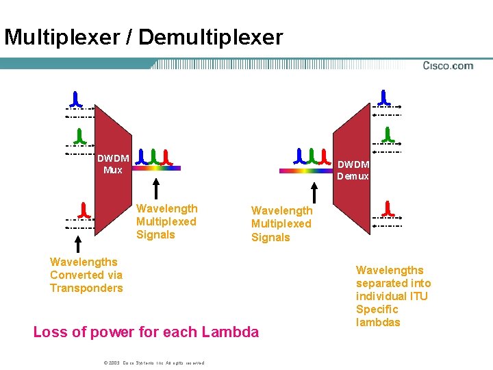
Multiplexer / Demultiplexer DWDM Mux DWDM Demux Wavelength Multiplexed Signals Wavelengths Converted via Transponders Loss of power for each Lambda © 2003, Cisco Systems, Inc. All rights reserved. Wavelengths separated into individual ITU Specific lambdas
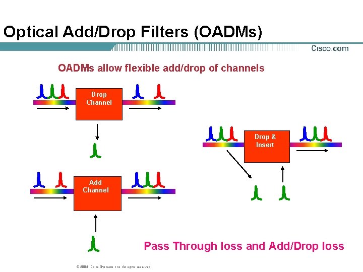
Optical Add/Drop Filters (OADMs) OADMs allow flexible add/drop of channels Drop Channel Drop & Insert Add Channel Pass Through loss and Add/Drop loss © 2003, Cisco Systems, Inc. All rights reserved.
Agenda • Introduction • Components • Forward Error Correction • DWDM Design • Summary © 2003, Cisco Systems, Inc. All rights reserved.
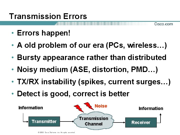
Transmission Errors • Errors happen! • A old problem of our era (PCs, wireless…) • Bursty appearance rather than distributed • Noisy medium (ASE, distortion, PMD…) • TX/RX instability (spikes, current surges…) • Detect is good, correct is better Information Transmitter © 2003, Cisco Systems, Inc. All rights reserved. Noise Transmission Channel Information Receiver
Error Correction • Error correcting codes both detect errors and correct them • Forward Error Correction (FEC) is a system adds additional information to the data stream corrects eventual errors that are caused by the transmission system. • Low BER achievable on noisy medium © 2003, Cisco Systems, Inc. All rights reserved.
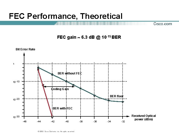
FEC Performance, Theoretical FEC gain 6. 3 d. B @ 10 -15 BER Bit Error Rate 1 BER without FEC 10 -10 Coding Gain BER floor 10 -20 BER with FEC 10 -30 -46 -44 -42 -40 © 2003, Cisco Systems, Inc. All rights reserved. -38 -36 -34 -32 Received Optical power (d. Bm)
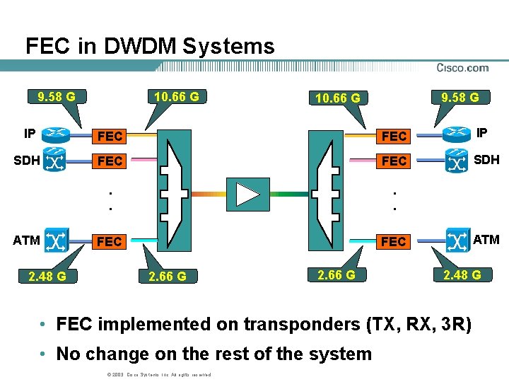
FEC in DWDM Systems 9. 58 G 10. 66 G IP FEC IP SDH FEC SDH . . FEC ATM 2. 48 G 2. 66 G ATM 2. 48 G • FEC implemented on transponders (TX, RX, 3 R) • No change on the rest of the system © 2003, Cisco Systems, Inc. All rights reserved.
Agenda • Introduction • Components • Forward Error Correction • DWDM Design • Summary © 2003, Cisco Systems, Inc. All rights reserved.
DWDM Design Topics • DWDM Challenges • Unidirectional vs. Bidirectional • Protection • Capacity • Distance © 2003, Cisco Systems, Inc. All rights reserved.
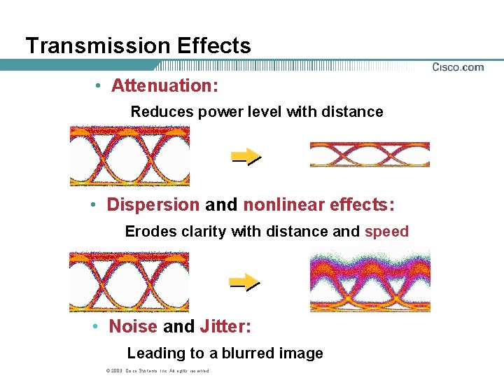
Transmission Effects • Attenuation: Reduces power level with distance • Dispersion and nonlinear effects: Erodes clarity with distance and speed • Noise and Jitter: Leading to a blurred image © 2003, Cisco Systems, Inc. All rights reserved.
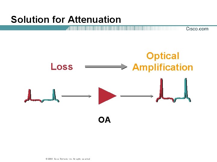
Solution for Attenuation Optical Amplification Loss OA © 2003, Cisco Systems, Inc. All rights reserved.
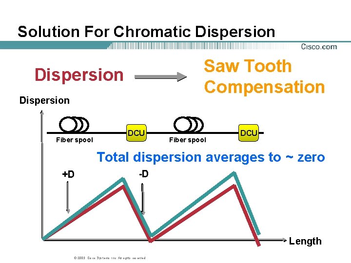
Solution For Chromatic Dispersion Saw Tooth Compensation Dispersion Fiber spool DCU Total dispersion averages to ~ zero +D -D Length © 2003, Cisco Systems, Inc. All rights reserved.
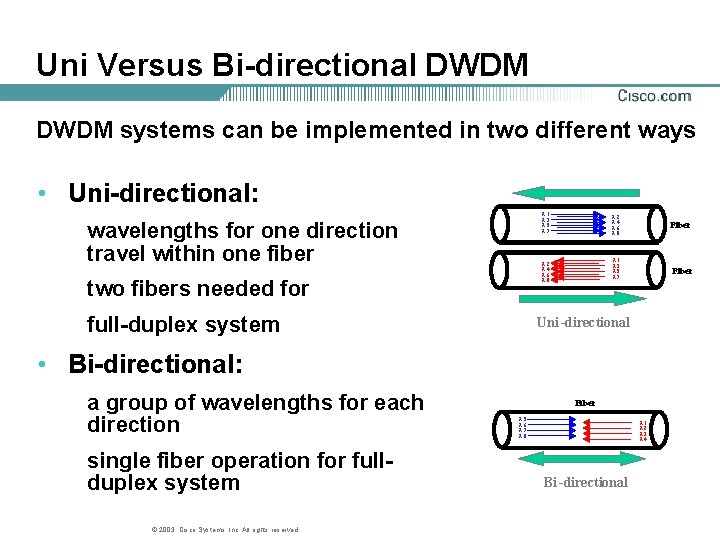
Uni Versus Bi-directional DWDM systems can be implemented in two different ways • Uni-directional: l 1 l 3 l 5 l 7 wavelengths for one direction travel within one fiber l 2 l 4 l 6 l 8 two fibers needed for full-duplex system l 2 l 4 l 6 l 8 Fiber l 1 l 3 l 5 l 7 Fiber Uni -directional • Bi-directional: a group of wavelengths for each direction single fiber operation for fullduplex system © 2003, Cisco Systems, Inc. All rights reserved. Fiber l 5 l 6 l 7 l 8 l 1 l 2 l 3 l 4 Bi -directional
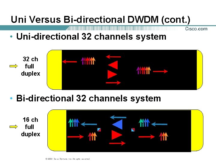
Uni Versus Bi-directional DWDM (cont. ) • Uni-directional 32 channels system 32 ch full duplex • Bi-directional 32 channels system 16 ch full duplex © 2003, Cisco Systems, Inc. All rights reserved.
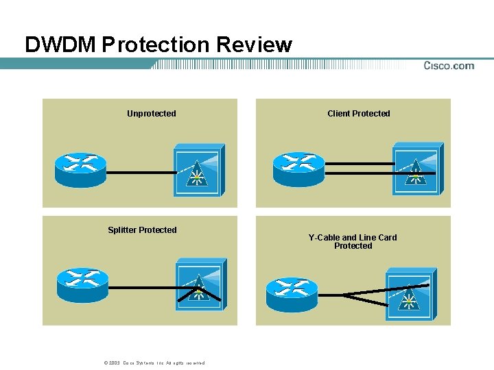
DWDM Protection Review Unprotected Splitter Protected © 2003, Cisco Systems, Inc. All rights reserved. Client Protected Y-Cable and Line Card Protected
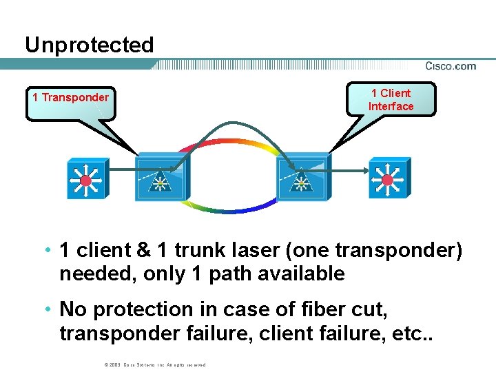
Unprotected 1 Transponder 1 Client Interface • 1 client & 1 trunk laser (one transponder) needed, only 1 path available • No protection in case of fiber cut, transponder failure, client failure, etc. . © 2003, Cisco Systems, Inc. All rights reserved.
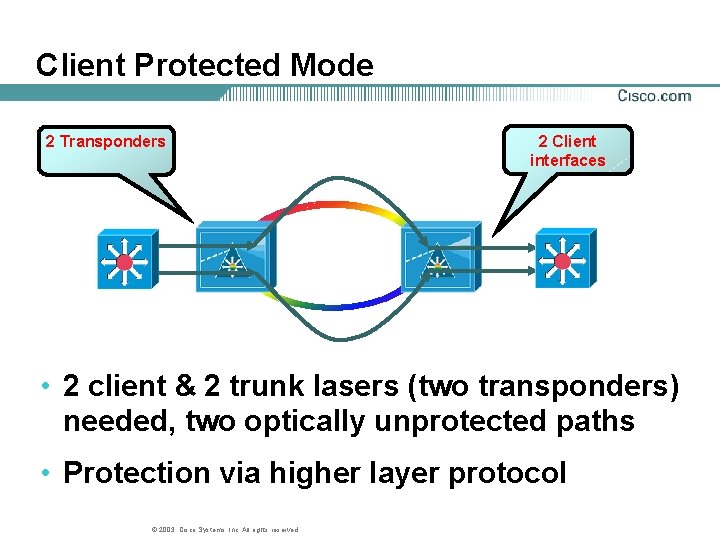
Client Protected Mode 2 Transponders 2 Client interfaces • 2 client & 2 trunk lasers (two transponders) needed, two optically unprotected paths • Protection via higher layer protocol © 2003, Cisco Systems, Inc. All rights reserved.
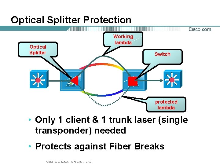
Optical Splitter Protection Working lambda Optical Splitter Switch protected lambda • Only 1 client & 1 trunk laser (single transponder) needed • Protects against Fiber Breaks © 2003, Cisco Systems, Inc. All rights reserved.
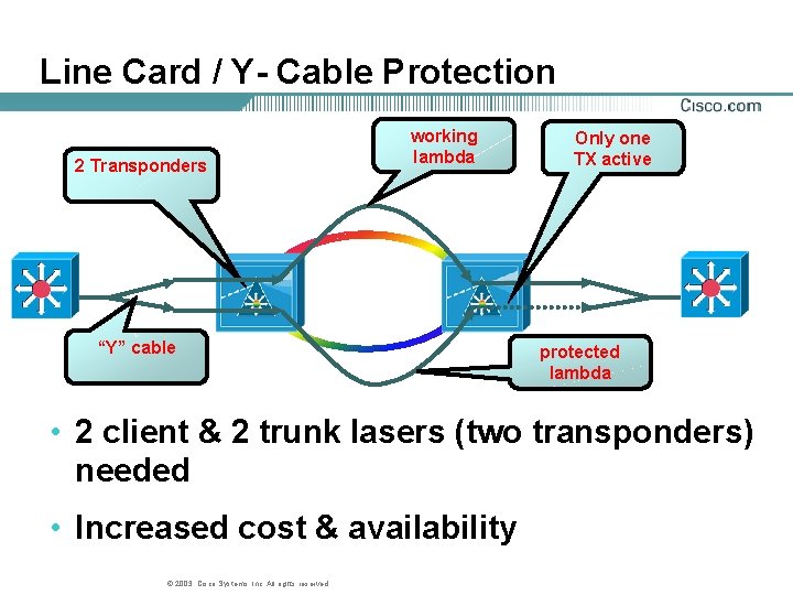
Line Card / Y- Cable Protection 2 Transponders working lambda “Y” cable Only one TX active protected lambda • 2 client & 2 trunk lasers (two transponders) needed • Increased cost & availability © 2003, Cisco Systems, Inc. All rights reserved.
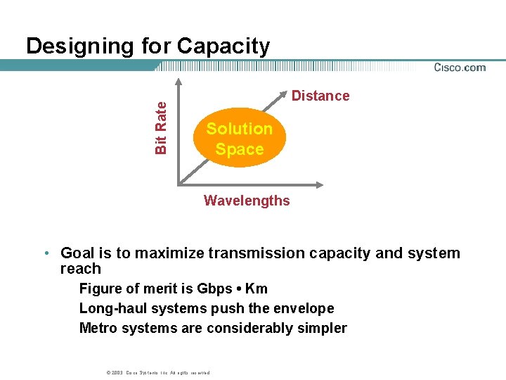
Bit Rate Designing for Capacity Distance Solution Space Wavelengths • Goal is to maximize transmission capacity and system reach Figure of merit is Gbps • Km Long-haul systems push the envelope Metro systems are considerably simpler © 2003, Cisco Systems, Inc. All rights reserved.
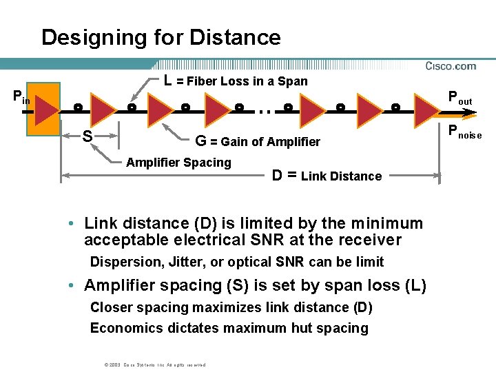
Designing for Distance L = Fiber Loss in a Span Pin Pout S G = Gain of Amplifier Spacing D = Link Distance • Link distance (D) is limited by the minimum acceptable electrical SNR at the receiver Dispersion, Jitter, or optical SNR can be limit • Amplifier spacing (S) is set by span loss (L) Closer spacing maximizes link distance (D) Economics dictates maximum hut spacing © 2003, Cisco Systems, Inc. All rights reserved. Pnoise
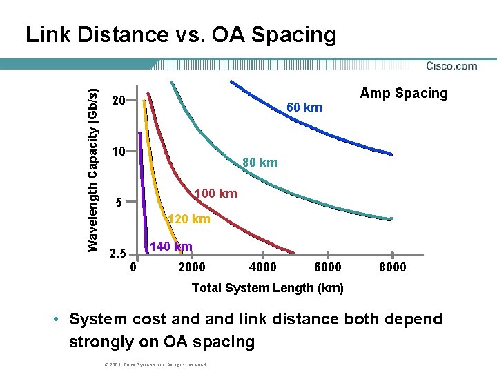
Wavelength Capacity (Gb/s) Link Distance vs. OA Spacing 20 60 km 10 Amp Spacing 80 km 100 km 5 120 km 140 km 2. 5 0 2000 4000 6000 8000 Total System Length (km) • System cost and link distance both depend strongly on OA spacing © 2003, Cisco Systems, Inc. All rights reserved.
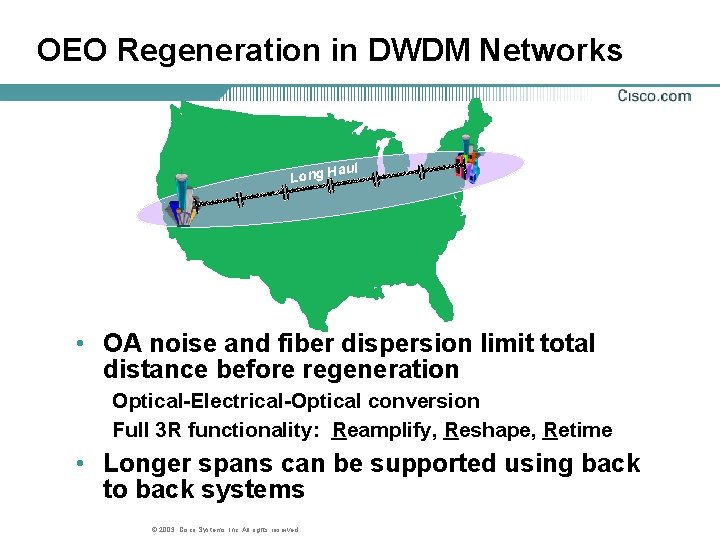
OEO Regeneration in DWDM Networks ul a Long H • OA noise and fiber dispersion limit total distance before regeneration Optical-Electrical-Optical conversion Full 3 R functionality: Reamplify, Reshape, Retime • Longer spans can be supported using back to back systems © 2003, Cisco Systems, Inc. All rights reserved.
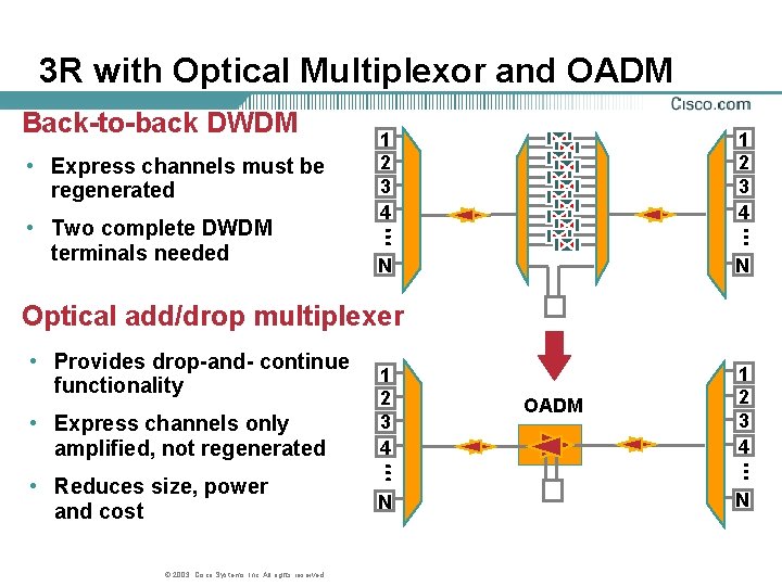
3 R with Optical Multiplexor and OADM Back-to-back DWDM • Express channels must be regenerated • Two complete DWDM terminals needed 1 2 3 4 N 7 Optical add/drop multiplexer • Provides drop-and- continue functionality • Express channels only amplified, not regenerated • Reduces size, power and cost © 2003, Cisco Systems, Inc. All rights reserved. 1 2 3 4 N 7 OADM 1 2 3 4 N 7
Agenda • Introduction • Components • Forward Error Correction • DWDM Design • Summary © 2003, Cisco Systems, Inc. All rights reserved.
DWDM Benefits • DWDM provides hundreds of Gbps of scalable transmission capacity today Provides capacity beyond TDM’s capability Supports incremental, modular growth Transport foundation for next generation networks © 2003, Cisco Systems, Inc. All rights reserved.
Metro DWDM • Metro DWDM is an emerging market for next generation DWDM equipment • The value proposition is very different from the long haul Rapid-service provisioning Protocol/bitrate transparency Carrier Class Optical Protection • Metro DWDM is not yet as widely deployed © 2003, Cisco Systems, Inc. All rights reserved.
- Slides: 87