
ONAP NF Modeling in SDC for Casablanca R
ONAP NF Modeling in SDC for Casablanca (R 3, 4 Q 2018) • NF (VNF/PNF) Modeling for R 3 • SDC Project Sept 14, 2018 version 6
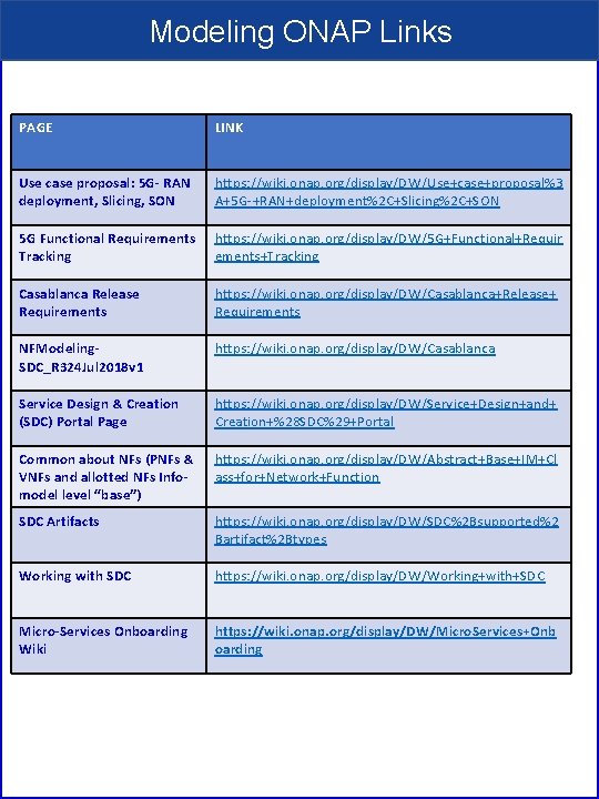
Modeling ONAP Links PAGE LINK Use case proposal: 5 G- RAN deployment, Slicing, SON https: //wiki. onap. org/display/DW/Use+case+proposal%3 A+5 G-+RAN+deployment%2 C+Slicing%2 C+SON 5 G Functional Requirements Tracking https: //wiki. onap. org/display/DW/5 G+Functional+Requir ements+Tracking Casablanca Release Requirements https: //wiki. onap. org/display/DW/Casablanca+Release+ Requirements NFModeling. SDC_R 324 Jul 2018 v 1 https: //wiki. onap. org/display/DW/Casablanca Service Design & Creation (SDC) Portal Page https: //wiki. onap. org/display/DW/Service+Design+and+ Creation+%28 SDC%29+Portal Common about NFs (PNFs & VNFs and allotted NFs Infomodel level “base”) https: //wiki. onap. org/display/DW/Abstract+Base+IM+Cl ass+for+Network+Function SDC Artifacts https: //wiki. onap. org/display/DW/SDC%2 Bsupported%2 Bartifact%2 Btypes Working with SDC https: //wiki. onap. org/display/DW/Working+with+SDC Micro-Services Onboarding Wiki https: //wiki. onap. org/display/DW/Micro. Services+Onb oarding
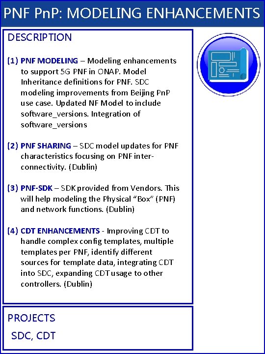
PNF Pn. P: MODELING ENHANCEMENTS DESCRIPTION (1) PNF MODELING – Modeling enhancements to support 5 G PNF in ONAP. Model Inheritance definitions for PNF. SDC modeling improvements from Beijing Pn. P use case. Updated NF Model to include software_versions. Integration of software_versions (2) PNF SHARING – SDC model updates for PNF characteristics focusing on PNF interconnectivity. (Dublin) (3) PNF-SDK – SDK provided from Vendors. This will help modeling the Physical “Box” (PNF) and network functions. (Dublin) (4) CDT ENHANCEMENTS - Improving CDT to handle complex config templates, multiple templates per PNF, identify different sources for template data, integrating CDT into SDC, expanding CDT usage to other controllers. (Dublin) PROJECTS SDC, CDT
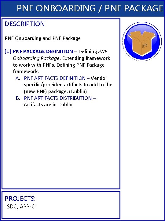
PNF ONBOARDING / PNF PACKAGE DESCRIPTION PNF Onboarding and PNF Package (1) PNF PACKAGE DEFINITION – Defining PNF Onboarding Package. Extending framework to work with PNFs. Defining PNF Package framework. A. PNF ARTIFACTS DEFINITION – Vendor specific/provided artifacts to add to the (new PNF) package. (Dublin) B. PNF ARTIFACTS DISTRIBUTION – Artifacts are in Dublin PROJECTS: SDC, APP-C
TERMS, CONCEPTS & PRINCIPLES • ONAP and NF Plug and Play for 5 G RAN • 5 G Use Case Team
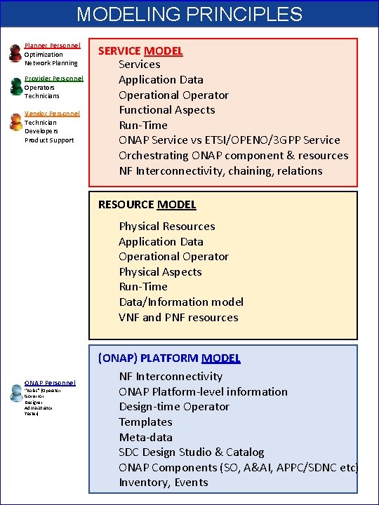
MODELING PRINCIPLES Planner Personnel Optimization Network Planning Provider Personnel Operators Technicians Vendor Personnel Technician Developers Product Support SERVICE MODEL Services Application Data Operational Operator Functional Aspects Run-Time ONAP Service vs ETSI/OPENO/3 GPP Service Orchestrating ONAP component & resources NF Interconnectivity, chaining, relations RESOURCE MODEL Physical Resources Application Data Operational Operator Physical Aspects Run-Time Data/Information model VNF and PNF resources ONAP Personnel “Roles” (Operator Governor Designer Administrator Tester) (ONAP) PLATFORM MODEL NF Interconnectivity ONAP Platform-level information Design-time Operator Templates Meta-data SDC Design Studio & Catalog ONAP Components (SO, A&AI, APPC/SDNC etc) Inventory, Events
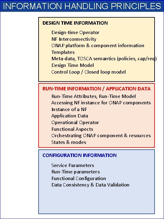
INFORMATION HANDLING PRINCIPLES DESIGN TIME INFORMATION Design-time Operator NF Interconnectivity ONAP platform & component information Templates Meta-data, TOSCA semantics (policies, cap/req) Design Time Model Control Loop / Closed loop model RUN-TIME INFORMATION / APPLICATION DATA Run-Time Attributes, Run-Time Model Accessing NF instance for ONAP components Instance of a NF Application Data Operational Operator Functional Aspects Orchestrating ONAP component & resources States & modes CONFIGURATION INFORMATION Service Parameters Run-Time parameters Functional Configuration Data Consistency & Data Validation
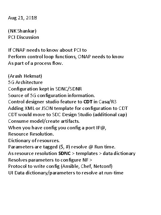
Aug 21, 2018 (NK Shankar) PCI Discussion If ONAP needs to know about PCI to Perform control loop functions, ONAP needs to know As part of a process flow. (Arash Hekmat) 5 G Architecture Configuration kept in SDNC/SDNR Source of 5 G configuration information. Control designer studio feature to CDT in Casa/R 3 Adding XML or JSON template for configuration to CDT would move to SDC Design Studio (additional cap) Consume model/create artifacts. When you have config you config a port IP@, Resource Resolution. Dictionary of resources. Parameters are tagged ($, #) resolve @ Run time. As resource resolution SDNC > templates > data dictionary Resolves parameters to configure NF > Protocol to write config (Ansible, Chef, Netconf) UI Data dictionary/parameters to resolve at run-time
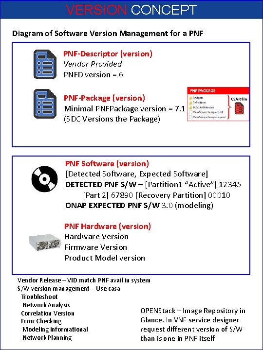
VERSION CONCEPT Diagram of Software Version Management for a PNF-Descriptor (version) Vendor Provided PNFD version = 6 PNF-Package (version) Minimal PNFPackage version = 7. 1 (SDC Versions the Package) PNF Software (version) [Detected Software, Expected Software] DETECTED PNF S/W – [Partition 1 “Active”] 12345 [Part 2] 67890 [Recovery Partition] 00010 ONAP EXPECTED PNF S/W 3. 0 (modeling) PNF Hardware (version) Hardware Version Firmware Version Product Model version Vendor Release – VID match PNF avail in system S/W version management – Use casa Troubleshoot Network Analysis OPENStack – Image Repository in Correlation Version Glance. In VNF service designer Error Checking request different version of S/W Modeling informational Network Planning than is one in PNF itself
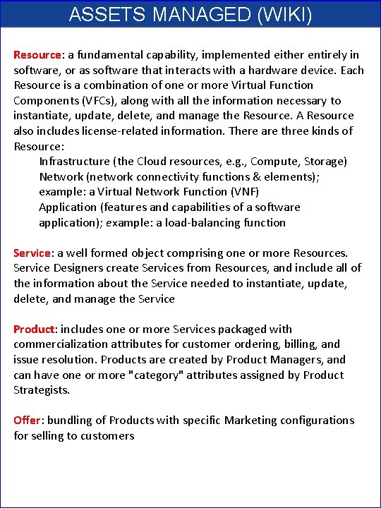
ASSETS MANAGED (WIKI) Resource: a fundamental capability, implemented either entirely in software, or as software that interacts with a hardware device. Each Resource is a combination of one or more Virtual Function Components (VFCs), along with all the information necessary to instantiate, update, delete, and manage the Resource. A Resource also includes license-related information. There are three kinds of Resource: Infrastructure (the Cloud resources, e. g. , Compute, Storage) Network (network connectivity functions & elements); example: a Virtual Network Function (VNF) Application (features and capabilities of a software application); example: a load-balancing function Service: a well formed object comprising one or more Resources. Service Designers create Services from Resources, and include all of the information about the Service needed to instantiate, update, delete, and manage the Service Product: includes one or more Services packaged with commercialization attributes for customer ordering, billing, and issue resolution. Products are created by Product Managers, and can have one or more "category" attributes assigned by Product Strategists. Offer: bundling of Products with specific Marketing configurations for selling to customers
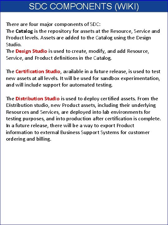
SDC COMPONENTS (WIKI) There are four major components of SDC: The Catalog is the repository for assets at the Resource, Service and Product levels. Assets are added to the Catalog using the Design Studio. The Design Studio is used to create, modify, and add Resource, Service, and Product definitions in the Catalog. The Certification Studio, available in a future release, is used to test new assets at all levels. It will be used for sandbox experimentation, and will include support for automated testing. The Distribution Studio is used to deploy certified assets. From the Distribution studio, new Product assets, including their underlying Resources and Services, are deployed into lab environments for testing purposes, and into production after certification is complete. In a future release, there will be a way to export Product information to external Business Support Systems for customer ordering and billing.
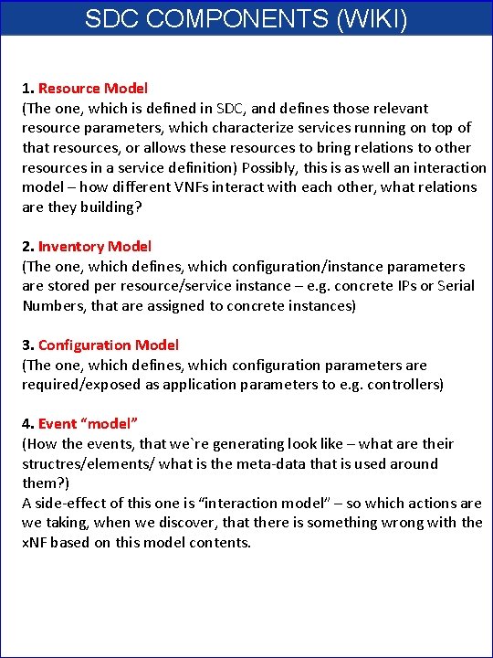
SDC COMPONENTS (WIKI) 1. Resource Model (The one, which is defined in SDC, and defines those relevant resource parameters, which characterize services running on top of that resources, or allows these resources to bring relations to other resources in a service definition) Possibly, this is as well an interaction model – how different VNFs interact with each other, what relations are they building? 2. Inventory Model (The one, which defines, which configuration/instance parameters are stored per resource/service instance – e. g. concrete IPs or Serial Numbers, that are assigned to concrete instances) 3. Configuration Model (The one, which defines, which configuration parameters are required/exposed as application parameters to e. g. controllers) 4. Event “model” (How the events, that we`re generating look like – what are their structres/elements/ what is the meta-data that is used around them? ) A side-effect of this one is “interaction model” – so which actions are we taking, when we discover, that there is something wrong with the x. NF based on this model contents.
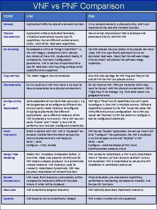
VNF vs PNF Comparison TOPIC VNF PNF Concept Application fulfills the role of a network function. It is a network element, a physical entity, which can implements the role of a network function. Physical Characteristic Application without dedicated hardware; Virtualized applications require specific capabilities; Run on different vendor servers. SRIOV, Inter-DPDK. Hardware capabilities. Has an actual physical asset that is deployed and associated directly with the PNF. On-boarding To onboard a VNF is to “bring it into ONAP” i. e. the VNF images, component VNF-C provide descriptors of these NFs. Deployment model, # components, functions. Configuration parameters. VNF is not tied or optimized for a specific hardware, only requiring perhaps some capability to be supported. For PNF provide the descriptors. Only provide the meta -data. PNF S/W specifically optimized to run on dedicated hardware. (Now) Not the software image. (Future) ONAP will provide the software image repository. Plug and Play The model triggers the orchestration. (See this slide package for PNF Plug and Play) at the end of Pn. P the PNF can provide service. Characteristics 5 G CU could be a VNF since there is no need to have an association to a physical environment. 5 G DU must be PNFs are Elements which may need to interact with the physical environment. PNF is “High-Touch” technology. E. g. Emit radio waves in a geographical area. Configurability & Deployment Easily adaptable to functions that you expect. E. g. Packet gateway to reconfigure as different NFs. Services easily create instances reconfigures including deployments (for different applications). Use a different instances of the VNF to provide a new service. For a VNF you can easily “delete” and “create” a new VNF to perform a new function. Configured dynamically. PNF has a “fixed” set of capabilities but can’t easily reconfigure it. One PNF in multiple services. Different capabilities exposed by the PNF. Reuse the same PNF with different services configuration. For a PNF you would not “destroy” a PNF but rather re-configure it. Can be configured dynamically. ONAP Interaction ONAP is started with VNF is “deployed” ondemand. Control from the ONAP perspective when a deployment of a VNF happens. DCAE – same Configure – Chef, Ansible PNF do not “deploy” application. Do not use multi-VIM. Only “configure” the application, the PNF is deployed. A technician goes to site and “deploys” a PNF. DCAE – same Configure –Implementation of PNF client. Communication protocol, Client Design Time Modeling Model VNF. Templates. Onboarded before. In Run-time. Make sure properly identify specific PNF instance already deployed. Vs a dynamically created instances. VNF instances could be created & instantiated dynamically. SDC may assumed instantiation of network function. PNF cannot be instantiated, a PNF is only instantiated when it “powers up” and connects to ONAP. Service Orchestration. PNF is instantiated by nature of a PNF installation & commission procedure. Service Orchestration VNF cloud, #VM resources consumption, define components implement different functions. Where & What will be deployed. Physical location, pre-provisioned capabilities, performance monitoring. Components installed. RUs for specific functions. Resources VNF dynamically assigned resources. PNF statically associated (hardware) resources. Capacity VNF Capacity can be dynamically changed PNF is static (number of cells supported)
NF Modeling in SDC IN CASABLANCA (R 3) • ONAP and NF Plug and Play for 5 G RAN • 5 G Use Case Team
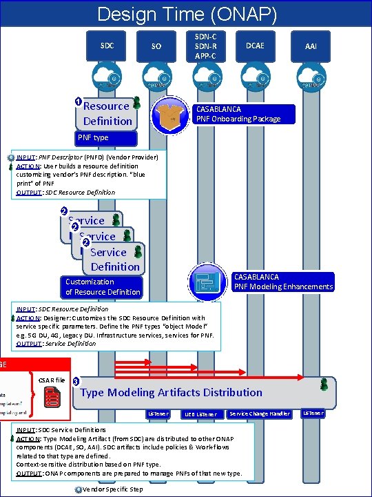
Design Time (ONAP) SDC 1 SO Resource Definition SDN-C SDN-R APP-C DCAE AAI CASABLANCA PNF Onboarding Package PNF type INPUT: PNF Descriptor (PNFD) (Vendor Provider) ACTION: User builds a resource definition customizing vendor’s PNF description. “blue print” of PNF OUTPUT: SDC Resource Definition 2 Service 2 Definition Service Definition CASABLANCA PNF Modeling Enhancements Customization of Resource Definition INPUT: SDC Resource Definition ACTION: Designer: Customizes the SDC Resource Definition with service specific parameters. Define the PNF types “object Model” e. g. 5 G DU, 4 G, Legacy DU. Infrastructure services, services for PNF. OUTPUT: Service Definition GE CSAR file 3 Type Modeling Artifacts Distribution Listener UEB Listener Service Change Handler INPUT: SDC Service Definitions ACTION: Type Modeling Artifact (from SDC) are distributed to other ONAP components (DCAE, SO, AAI). SDC artifacts include policies & Work-flows related to that type are defined. Context-sensitive distribution based on PNF type. OUTPUT: ONAP components are prepared to manage PNFs of that new type. Vendor Specific Step Listener
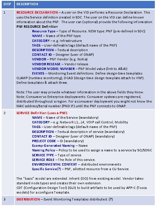
STEP DESCRIPTION 1 RESOURCE DECLARATION – A user on the VID performs a Resource Declaration. This uses the Service definition created in SDC. The user on the VID can define known information about the PNF. The user can (optional) provide the following information PNF RESOURCE Definition Resource Type – Type of Resource. NEW type: PNF (pre-defined in SDC) NAME – Name of the PNF type CATEGORY – e. g. Infrastructure TAGS – User-definable tags (default name of the PNF) DESCRIPTION – Textual description CONTACT ID – Designer (user of ONAP) VENDOR – PNF Vendor (e. g. Nokia) VENDOR RELEASE – Vendor release VENDOR MODEL NUMBER – PNF Model value (link to A&AI) EVENTS – Monitoring Event definitions. Define design-time templates. CLAMP (runtime monitoring), DCAD (design time design template attach to VNF). Define templates & attach them. Note: The user may provide whatever information in the above fields they know. Note: Consumer vs Enterprise deployments. Consumer systems pre-registered, distributed throughout a region. For a consumer deployment you might not know the MAC address/Serial number (PND IF) until the PNF connects to ONAP. 2 SERVICE Definition (uses a PNF) NAME – Name of the Service (mandatory) CATEGORY – e. g. Network L 1…L 4, VOIP call Control, Mobility TAGS – User-definable tags (default name of the PNF) DESCRIPTION – Textual description of service (mandatory) CONTACT ID – Designer (user of ONAP) (mandatory) PROJECT CODE – ID (mandatory) Ecomp-Generated Naming – Name Naming Policy – Policy to be used to assign a name to a service by SO/SDNC SERVICE TYPE – Type of service SERVICE ROLE – The Role of this service. ENVIRONMENTAL CONTEXT – distributed environments Specific Service(? ) – PNF, allotted resource from a CU Service The “basic” model are extended. Inherit (OO) from existing model. Vendor takes standard node types and creates their own extension. CDT (Configuration Design Tool) (GUI) to build artifacts to be used by APP-C (Tosca models) for a configure Template. 3 DISTRIBUTION – Event Monitoring Templates distributed. (? )
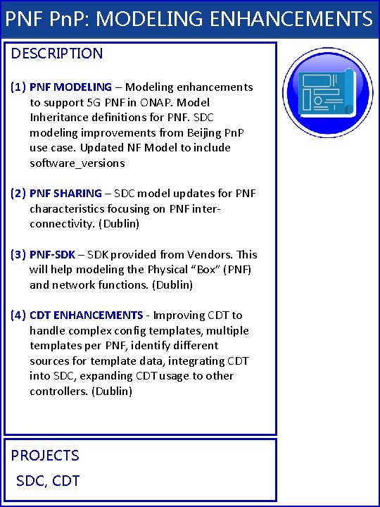
PNF Pn. P: MODELING ENHANCEMENTS DESCRIPTION (1) PNF MODELING – Modeling enhancements to support 5 G PNF in ONAP. Model Inheritance definitions for PNF. SDC modeling improvements from Beijing Pn. P use case. Updated NF Model to include software_versions (2) PNF SHARING – SDC model updates for PNF characteristics focusing on PNF interconnectivity. (Dublin) (3) PNF-SDK – SDK provided from Vendors. This will help modeling the Physical “Box” (PNF) and network functions. (Dublin) (4) CDT ENHANCEMENTS - Improving CDT to handle complex config templates, multiple templates per PNF, identify different sources for template data, integrating CDT into SDC, expanding CDT usage to other controllers. (Dublin) PROJECTS SDC, CDT
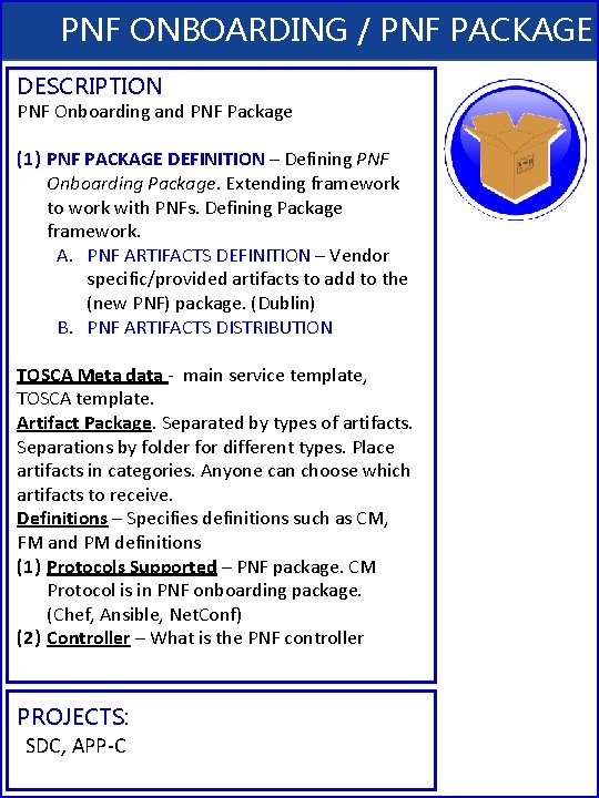
PNF ONBOARDING / PNF PACKAGE DESCRIPTION PNF Onboarding and PNF Package (1) PNF PACKAGE DEFINITION – Defining PNF Onboarding Package. Extending framework to work with PNFs. Defining Package framework. A. PNF ARTIFACTS DEFINITION – Vendor specific/provided artifacts to add to the (new PNF) package. (Dublin) B. PNF ARTIFACTS DISTRIBUTION TOSCA Meta data - main service template, TOSCA template. Artifact Package. Separated by types of artifacts. Separations by folder for different types. Place artifacts in categories. Anyone can choose which artifacts to receive. Definitions – Specifies definitions such as CM, FM and PM definitions (1) Protocols Supported – PNF package. CM Protocol is in PNF onboarding package. (Chef, Ansible, Net. Conf) (2) Controller – What is the PNF controller PROJECTS: SDC, APP-C
NF SDC & Modeling Project Impacts Overview • ONAP and SDC NF Modeling for 5 G RAN • 5 G SDC Project
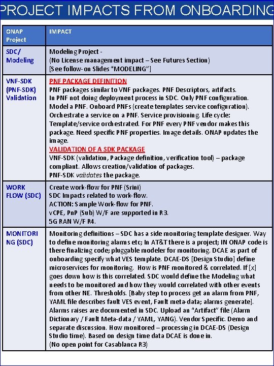
PROJECT IMPACTS FROM ONBOARDING ONAP Project IMPACT SDC/ Modeling Project (No License management impact – See Futures Section) [See follow-on Slides “MODELING”] VNF-SDK (PNF-SDK) Validation PNF PACKAGE DEFINITION PNF packages similar to VNF packages. PNF Descriptors, artifacts. In PNF not doing deployment process in SDC. Only PNF configuration. Model a PNF. Onboard PNFs (create templates service configuration). Orchestrate a service on a PNF. Service provisioning. Life cycle: Template/service orchestrated. For PNF every PNF vendor makes this package. Need specific PNF properties. Image details. ONAP updates the image. VALIDATION OF A SDK PACKAGE VNF-SDK (validation, Package definition, verification tool) – package compliant. Allows creation/validation of packages. PNF-SDK validates the package. WORK FLOW (SDC) Create work-flow for PNF (Srini) SDC Impacts related to work-flow. ACTION: Sample Work-flow for PNF. v. CPE, Pn. P (Sub) W/F are supported in R 3. 5 G RAN W/F R 4. MONITORI NG (SDC) Monitoring definitions – SDC has a side monitoring template designer. Way to define monitoring alarms etc; In AT&T there is a project; IN ONAP code is there finalizing code; pluggable modeler for monitoring. DCAE as part of onboarding specify what VES template. DCAE-DS [Design Studio] define microservices for monitoring. How is PNF monitored & correlated. If [x] goes down how is this correlated. SDC would define the Modeling what needs to be monitored and how they would correlated with other events from other NE. Thresholds. [Baby step to process get an alarm from PNF, YAML file describes fault VES event, Fault meta-data; alarms generate]. Alarms raises are documented in SDC. Upload an “Artifact” file (Alarm Dictionary / Fault Meta-data / YAML, YANG). Vendor Specific. Demo and separate discussion. How monitored – processing in DCAE-DS (Design Studio time). Based on design time data DCAE is done in. (No open point for Casablanca R 3)
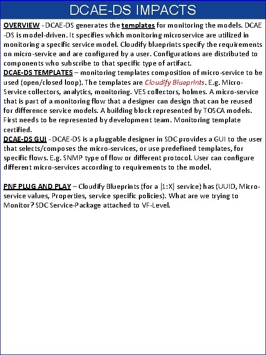
DCAE-DS IMPACTS OVERVIEW - DCAE-DS generates the templates for monitoring the models. DCAE -DS is model-driven. It specifies which monitoring microservice are utilized in monitoring a specific service model. Cloudify blueprints specify the requirements on micro-service and are configured by a user. Configurations are distributed to components who subscribe to that specific type of artifact. DCAE-DS TEMPLATES – monitoring templates composition of micro-service to be used (open/closed loop). The templates are Cloudify Blueprints. E. g. Micro. Service collectors, analytics, monitoring. VES collectors, holmes. A micro-service that is part of a monitoring flow that a designer can design that can be reused for difference service models. A building block represented by TOSCA models. First needs to be represented by development team. Monitoring template certified. DCAE-DS GUI - DCAE-DS is a pluggable designer in SDC provides a GUI to the user that selects/composes the micro-services, or use predefined templates, for specific flows. E. g. SNMP type of flow or different protocol. User can configure different micro-services according to requirements to the model. PNF PLUG AND PLAY – Cloudify Blueprints (for a [1: X] service) has (UUID, Microservice values, Properties, service specific policies). What are we trying to Monitor? SDC Service-Package attached to VF-Level.
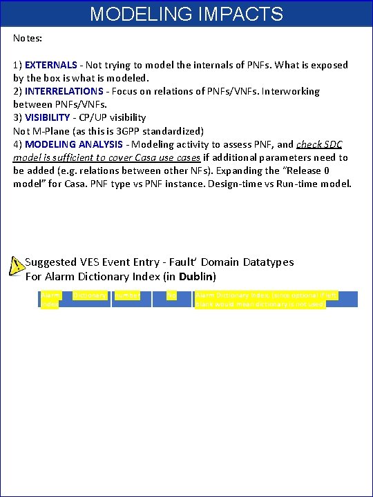
MODELING IMPACTS Notes: 1) EXTERNALS - Not trying to model the internals of PNFs. What is exposed by the box is what is modeled. 2) INTERRELATIONS - Focus on relations of PNFs/VNFs. Interworking between PNFs/VNFs. 3) VISIBILITY - CP/UP visibility Not M-Plane (as this is 3 GPP standardized) 4) MODELING ANALYSIS - Modeling activity to assess PNF, and check SDC model is sufficient to cover Casa use cases if additional parameters need to be added (e. g. relations between other NFs). Expanding the “Release 0 model” for Casa. PNF type vs PNF instance. Design-time vs Run-time model. Suggested VES Event Entry - Fault’ Domain Datatypes For Alarm Dictionary Index (in Dublin) Alarm Index Dictionary number No Alarm Dictionary Index, (since optional if left blank would mean dictionary is not used)
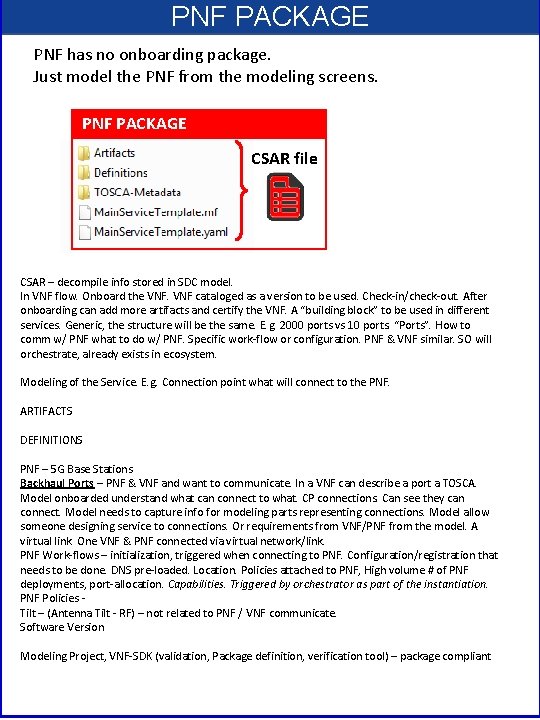
PNF PACKAGE PNF has no onboarding package. Just model the PNF from the modeling screens. PNF PACKAGE CSAR file CSAR – decompile info stored in SDC model. In VNF flow. Onboard the VNF cataloged as a version to be used. Check-in/check-out. After onboarding can add more artifacts and certify the VNF. A “building block” to be used in different services. Generic, the structure will be the same. E. g. 2000 ports vs 10 ports. “Ports”. How to comm w/ PNF what to do w/ PNF. Specific work-flow or configuration. PNF & VNF similar. SO will orchestrate, already exists in ecosystem. Modeling of the Service. E. g. Connection point what will connect to the PNF. ARTIFACTS DEFINITIONS PNF – 5 G Base Stations Backhaul Ports – PNF & VNF and want to communicate. In a VNF can describe a port a TOSCA. Model onboarded understand what can connect to what. CP connections. Can see they can connect. Model needs to capture info for modeling parts representing connections. Model allow someone designing service to connections. Or requirements from VNF/PNF from the model. A virtual link. One VNF & PNF connected via virtual network/link. PNF Work-flows – initialization, triggered when connecting to PNF. Configuration/registration that needs to be done. DNS pre-loaded. Location. Policies attached to PNF, High volume # of PNF deployments, port-allocation. Capabilities. Triggered by orchestrator as part of the instantiation. PNF Policies - Tilt – (Antenna Tilt - RF) – not related to PNF / VNF communicate. Software Version Modeling Project, VNF-SDK (validation, Package definition, verification tool) – package compliant
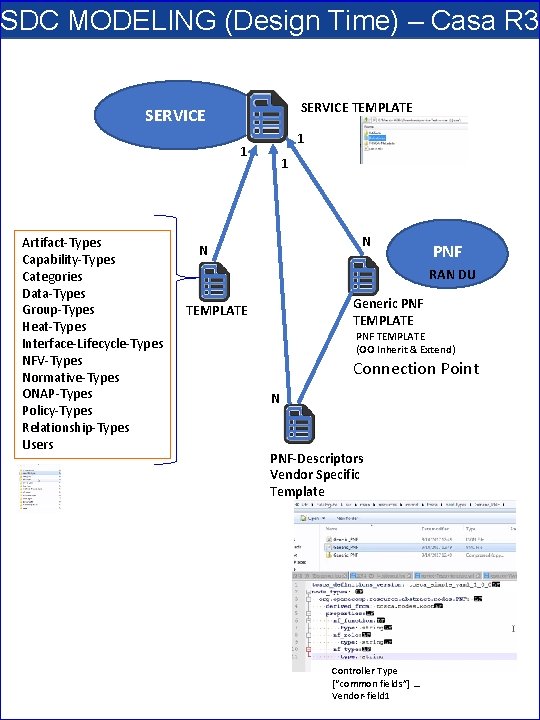
SDC MODELING (Design Time) – Casa R 3 SERVICE TEMPLATE SERVICE 1 1 Artifact-Types Capability-Types Categories Data-Types Group-Types Heat-Types Interface-Lifecycle-Types NFV-Types Normative-Types ONAP-Types Policy-Types Relationship-Types Users 1 N N PNF RAN DU Generic PNF TEMPLATE (OO Inherit & Extend) Connection Point N PNF-Descriptors Vendor Specific Template Controller Type [“common fields”] … Vendor-field 1
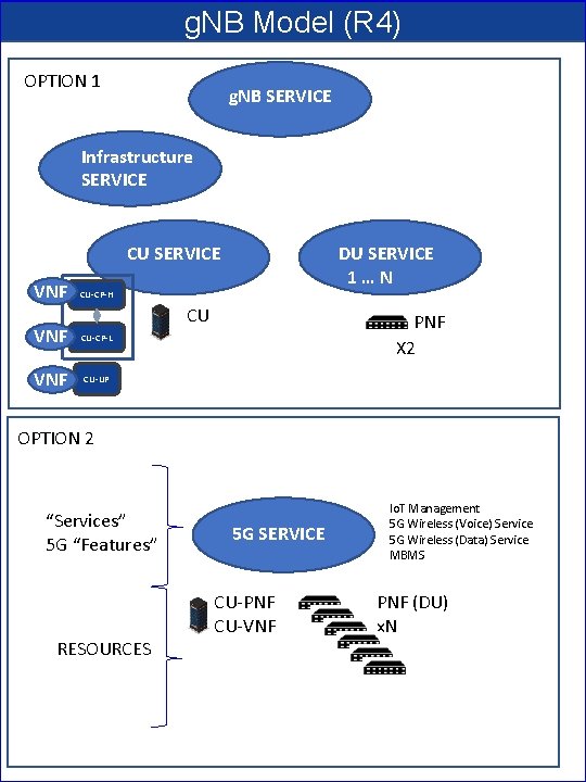
g. NB Model (R 4) OPTION 1 g. NB SERVICE Infrastructure SERVICE CU SERVICE VNF DU SERVICE 1…N CU-CP-H CU VNF CU-CP-L VNF CU-UP PNF X 2 OPTION 2 “Services” 5 G “Features” RESOURCES 5 G SERVICE CU-PNF CU-VNF Io. T Management 5 G Wireless (Voice) Service 5 G Wireless (Data) Service MBMS PNF (DU) x. N
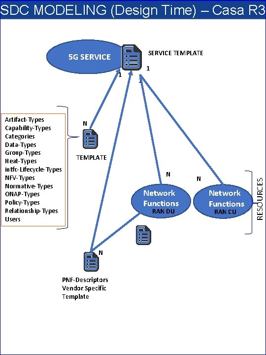
SDC MODELING (Design Time) – Casa R 3 SERVICE TEMPLATE 5 G SERVICE 1 1 N TEMPLATE N Network Functions RAN DU N PNF-Descriptors Vendor Specific Template N Network Functions RAN CU RESOURCES Artifact-Types Capability-Types Categories Data-Types Group-Types Heat-Types intfc-Lifecycle-Types NFV-Types Normative-Types ONAP-Types Policy-Types Relationship-Types Users 1
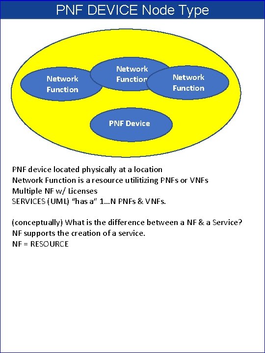
PNF DEVICE Node Type Network Function PNF Device PNF device located physically at a location Network Function is a resource utilitizing PNFs or VNFs Multiple NF w/ Licenses SERVICES (UML) “has a” 1…N PNFs & VNFs. (conceptually) What is the difference between a NF & a Service? NF supports the creation of a service. NF = RESOURCE
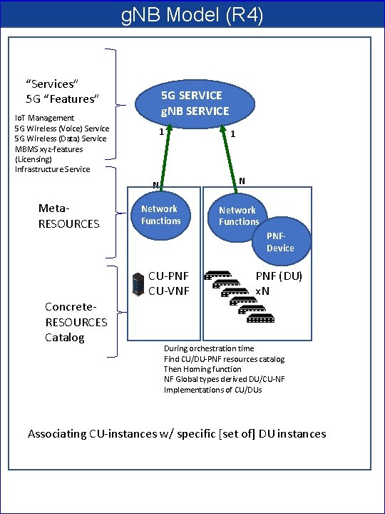
g. NB Model (R 4) “Services” 5 G “Features” 5 G SERVICE g. NB SERVICE Io. T Management 5 G Wireless (Voice) Service 5 G Wireless (Data) Service MBMS xyz-features (Licensing) Infrastructure Service 1 N N Meta. RESOURCES Concrete. RESOURCES Catalog 1 Network Functions PNFDevice CU-PNF CU-VNF PNF (DU) x. N During orchestration time Find CU/DU-PNF resources catalog Then Homing function NF Global types derived DU/CU-NF Implementations of CU/DUs Associating CU-instances w/ specific [set of] DU instances
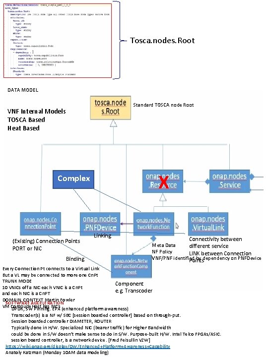
Tosca. nodes. Root DATA MODEL Standard TOSCA node Root VNF Internal Models TOSCA Based Heat Based X Complex (Existing) Connection Points PORT or NIC Binding Linking Connectivity between Meta Data different service NF Policy LINK between Connection VNF/PNF identified by dependency on PNFDevice Points Every Connection Pt connects to a Virtual Link But a VL may be connected to more one Cn. Pt TRUNK MODE Component 10 VNICs off a NIC each VNIC is a Cn. Pt e. g. Transcoder and each NIC is a Cn. PT DOMAIN, CONTEXT Martin Fowler SOFTWARE ACCELERATION VM Compujte. Host has NICs DPDK, SW Pinning. EPA (enhanced platform awareness) Transcoder(s) is a NF w/ SBC [session boarded controller] based on through-put. Session boarded controller DIAMETER, ROUTER Typically done in H/W. Specialized NIC (bearer traffic) for Higher Bandwidth could be done in S/W doesn’t make sense to do in S/W. Purpose-built H/W. Intel Telco FPGAs/ASIC. session board controller, is a network device. [Fred Feisullin VZW] https: //wiki. onap. org/display/DW/Enhanced+Platform+Awareness+Capability Anatoly Katzman (Monday 10 AM data modeling)
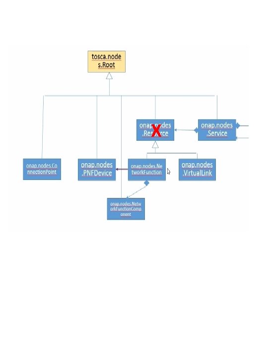
X
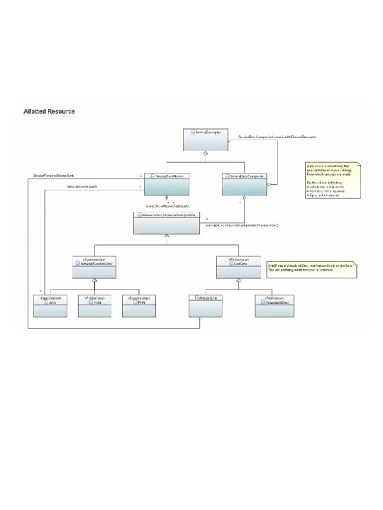
NFD DESCRIPTOR (PNFD, VNFD) • ONAP and SDC NF Modeling for 5 G RAN • 5 G SDC Project
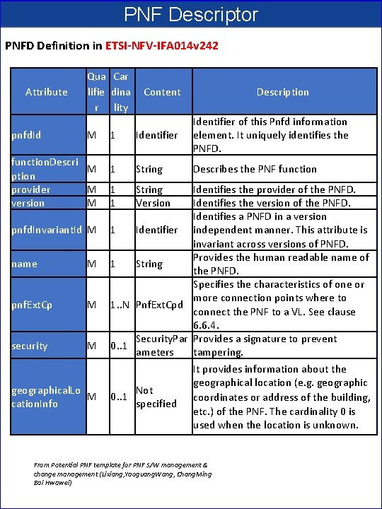
PNF Descriptor PNFD Definition in ETSI-NFV-IFA 014 v 242 Attribute pnfd. Id Qua Car lifie dina r lity M function. Descri M ption provider M version M pnfd. Invariant. Id M name M pnf. Ext. Cp M security M geographical. Lo M cation. Info Content Description 1 Identifier of this Pnfd information element. It uniquely identifies the PNFD. 1 String Describes the PNF function 1 1 String Version Identifies the provider of the PNFD. Identifies the version of the PNFD. Identifies a PNFD in a version 1 Identifier independent manner. This attribute is invariant across versions of PNFD. Provides the human readable name of 1 String the PNFD. Specifies the characteristics of one or more connection points where to 1. . N Pnf. Ext. Cpd connect the PNF to a VL. See clause 6. 6. 4. Security. Par Provides a signature to prevent 0. . 1 ameters tampering. It provides information about the geographical location (e. g. geographic Not 0. . 1 coordinates or address of the building, specified etc. ) of the PNF. The cardinality 0 is used when the location is unknown. From Potential PNF template for PNF S/W management & change management (Lixiang, Yaoguang. Wang, Chang. Ming Bai Hwawei)
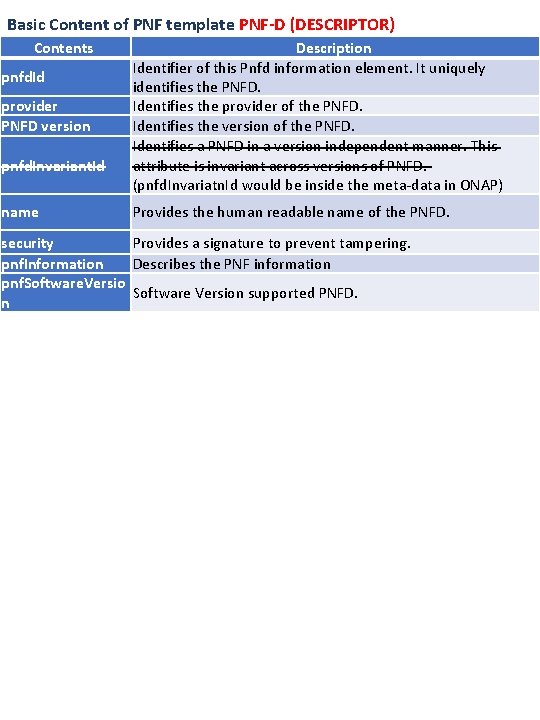
Basic Content of PNF template PNF-D (DESCRIPTOR) Contents pnfd. Id provider PNFD version pnfd. Invariant. Id name Description Identifier of this Pnfd information element. It uniquely identifies the PNFD. Identifies the provider of the PNFD. Identifies the version of the PNFD. Identifies a PNFD in a version independent manner. This attribute is invariant across versions of PNFD. (pnfd. Invariatn. Id would be inside the meta-data in ONAP) Provides the human readable name of the PNFD. security Provides a signature to prevent tampering. pnf. Information Describes the PNF information pnf. Software. Versio Software Version supported PNFD. n
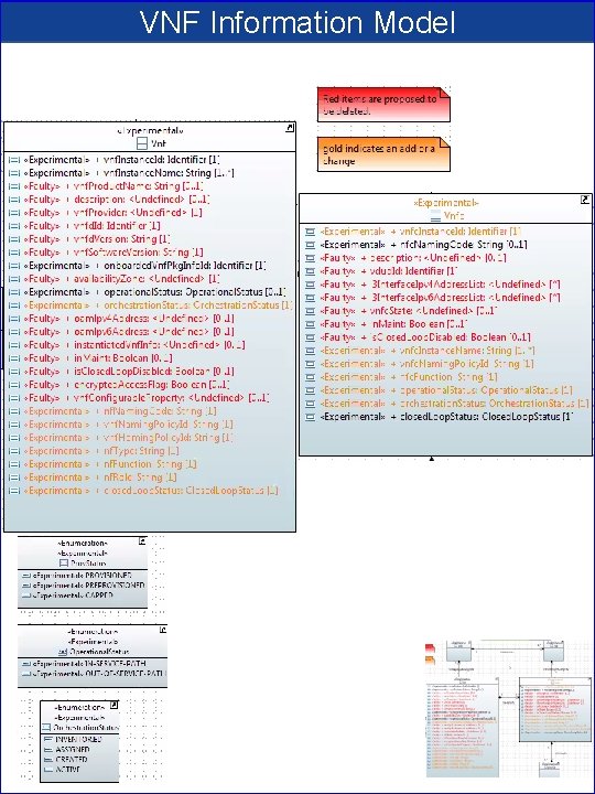
VNF Information Model
NF MODEL • ONAP and SDC NF Modeling for 5 G RAN • 5 G SDC Project
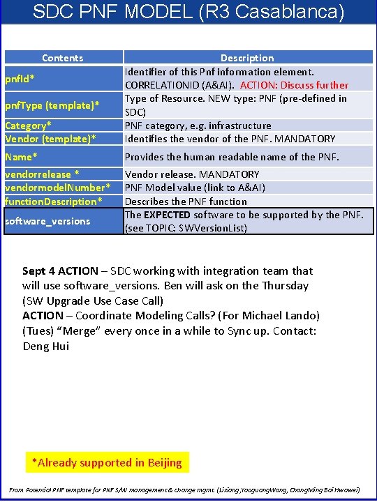
SDC PNF MODEL (R 3 Casablanca) Contents Category* Vendor (template)* Description Identifier of this Pnf information element. CORRELATIONID (A&AI). ACTION: Discuss further Type of Resource. NEW type: PNF (pre-defined in SDC) PNF category, e. g. infrastructure Identifies the vendor of the PNF. MANDATORY Name* Provides the human readable name of the PNF. vendorrelease * vendormodel. Number* function. Description* Vendor release. MANDATORY PNF Model value (link to A&AI) Describes the PNF function The EXPECTED software to be supported by the PNF. (see TOPIC: SWVersion. List) pnf. Id* pnf. Type (template)* software_versions Sept 4 ACTION – SDC working with integration team that will use software_versions. Ben will ask on the Thursday (SW Upgrade Use Call) ACTION – Coordinate Modeling Calls? (For Michael Lando) (Tues) “Merge” every once in a while to Sync up. Contact: Deng Hui *Already supported in Beijing From Potential PNF template for PNF S/W management & change mgmt. (Lixiang, Yaoguang. Wang, Chang. Ming Bai Hwawei)
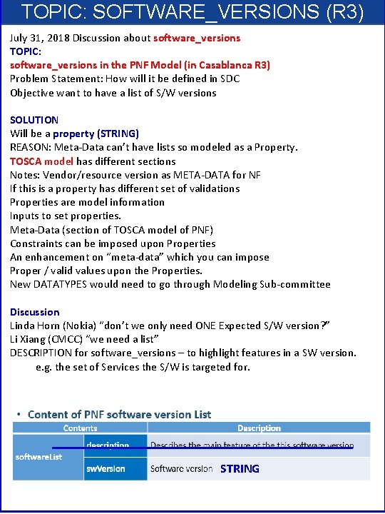
TOPIC: SOFTWARE_VERSIONS (R 3) July 31, 2018 Discussion about software_versions TOPIC: software_versions in the PNF Model (in Casablanca R 3) Problem Statement: How will it be defined in SDC Objective want to have a list of S/W versions SOLUTION Will be a property (STRING) REASON: Meta-Data can’t have lists so modeled as a Property. TOSCA model has different sections Notes: Vendor/resource version as META-DATA for NF If this is a property has different set of validations Properties are model information Inputs to set properties. Meta-Data (section of TOSCA model of PNF) Constraints can be imposed upon Properties An enhancement on “meta-data” which you can impose Proper / valid values upon the Properties. New DATATYPES would need to go through Modeling Sub-committee Discussion Linda Horn (Nokia) “don’t we only need ONE Expected S/W version? ” Li Xiang (CMCC) “we need a list” DESCRIPTION for software_versions – to highlight features in a SW version. e. g. the set of Services the S/W is targeted for. STRING
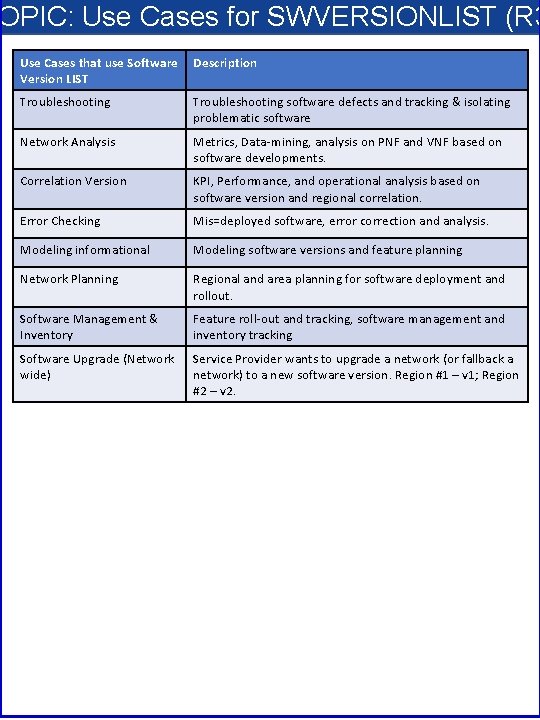
OPIC: Use Cases for SWVERSIONLIST (R 3 Use Cases that use Software Version LIST Description Troubleshooting software defects and tracking & isolating problematic software Network Analysis Metrics, Data-mining, analysis on PNF and VNF based on software developments. Correlation Version KPI, Performance, and operational analysis based on software version and regional correlation. Error Checking Mis=deployed software, error correction and analysis. Modeling informational Modeling software versions and feature planning Network Planning Regional and area planning for software deployment and rollout. Software Management & Inventory Feature roll-out and tracking, software management and inventory tracking Software Upgrade (Network wide) Service Provider wants to upgrade a network (or fallback a network) to a new software version. Region #1 – v 1; Region #2 – v 2.
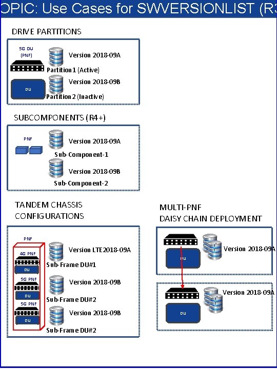
OPIC: Use Cases for SWVERSIONLIST (R 3 DRIVE PARTITIONS 5 G DU (PNF) Version 2018 -09 A Partition 1 (Active) Version 2018 -09 B DU Partition 2 (Inactive) SUBCOMPONENTS (R 4+) PNF Version 2018 -09 A Sub-Component-1 Version 2018 -09 B Sub-Component-2 TANDEM CHASSIS CONFIGURATIONS MULTI-PNF DAISY CHAIN DEPLOYMENT PNF 4 G PNF DU 5 G PNF Version 2018 -09 A Version LTE 2018 -09 A Sub-Frame DU#1 DU Version 2018 -09 B Version 2018 -09 A Sub-Frame DU#2 Version 2018 -09 B DU Sub-Frame DU#2 DU
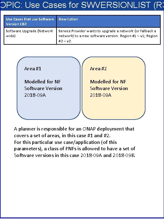
OPIC: Use Cases for SWVERSIONLIST (R 3 Use Cases that use Software Version LIST Description Software Upgrade (Network wide) Service Provider wants to upgrade a network (or fallback a network) to a new software version. Region #1 – v 1; Region #2 – v 2. Area #1 Area #2 Modelled for NF Software Version 2018 -09 A A planner is responsible for an ONAP deployment that covers a set of areas, in this case #1 and #2. For this particular use case/application (of this parameters), a class of PNFs is allowed to have a set of Software versions in this case 2018 -09 A and 2018 -09 B.
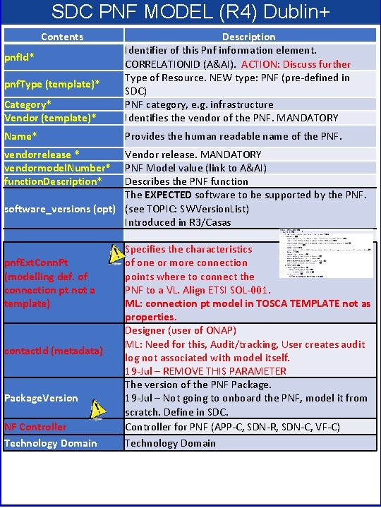
SDC PNF MODEL (R 4) Dublin+ Contents Category* Vendor (template)* Description Identifier of this Pnf information element. CORRELATIONID (A&AI). ACTION: Discuss further Type of Resource. NEW type: PNF (pre-defined in SDC) PNF category, e. g. infrastructure Identifies the vendor of the PNF. MANDATORY Name* Provides the human readable name of the PNF. pnf. Id* pnf. Type (template)* vendorrelease * vendormodel. Number* function. Description* Vendor release. MANDATORY PNF Model value (link to A&AI) Describes the PNF function The EXPECTED software to be supported by the PNF. software_versions (opt) (see TOPIC: SWVersion. List) Introduced in R 3/Casas pnf. Ext. Conn. Pt (modelling def. of connection pt not a template) contact. Id (metadata) Package. Version NF Controller Technology Domain Specifies the characteristics of one or more connection points where to connect the PNF to a VL. Align ETSI SOL-001. ML: connection pt model in TOSCA TEMPLATE not as properties. Designer (user of ONAP) ML: Need for this, Audit/tracking, User creates audit log not associated with model itself. 19 -Jul – REMOVE THIS PARAMETER The version of the PNF Package. 19 -Jul – Not going to onboard the PNF, model it from scratch. Define in SDC. Controller for PNF (APP-C, SDN-R, SDN-C, VF-C) Technology Domain
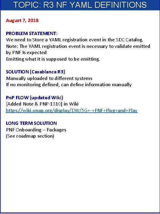
TOPIC: R 3 NF YAML DEFINITIONS August 7, 2018 PROBLEM STATEMENT: We need to Store a YAML registration event in the SDC Catalog. Note: The YAML registration event is necessary to validate emitted by PNF Is expected Emitting what it is supposed to be emitting. SOLUTION (Casablanca R 3) Manually uploaded to different systems If no monitoring defined, can define information manually Pn. P FLOW (updated Wiki) [Added Note & PNP-1310] in Wiki https: //wiki. onap. org/display/DW/5 G+-+PNF+Plug+and+Play LONG TERM SOLUTION PNF Onboarding – Packages (See roadmap section)
RAN CONCEPT • ONAP and SDC NF Modeling for 5 G RAN • 5 G SDC Project
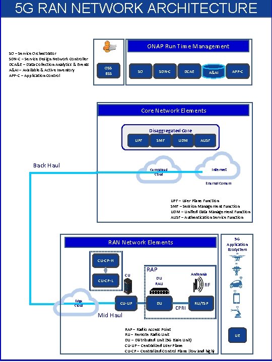
5 G RAN NETWORK ARCHITECTURE ONAP Run Time Management SO – Service Orchestrator SDN-C – Service Design Network Controller DCA&E – Data Collection Analytics & Events A&AI – Available & Active Inventory APP-C – Application Control OSS BSS SO SDN-C DCAE APP-C A&AI Core Network Elements Disaggregated Core UPF Back Haul SMF UDM AUSF Internet Centralized Cloud External Content UPF – User Plane Function SMF – Session Management Function UDM – Unified Data Management Function AUSF – Authentication Service Function 5 G Application Ecosystem RAN Network Elements CU-CP-H CU CU-CP-L Edge Cloud CU-UP Mid Haul RAP Antenna DU RAU DU RF CPRI RU/TSP RAP – Radio Access Point RU – Remote Radio Unit DU – Distributed Unit (5 G Base Unit) CU-UP – Centralized User Plane CU-CP – Centralized Control Plane (low and high) UE
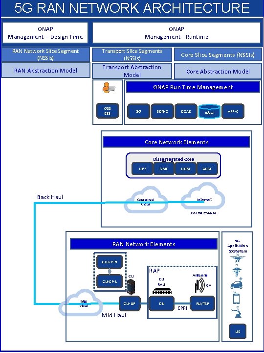
5 G RAN NETWORK ARCHITECTURE ONAP Management – Design Time ONAP Management - Runtime RAN Network Slice Segment (NSSIs) Transport Slice Segments (NSSIs) Core Slice Segments (NSSIs) RAN Abstraction Model Transport Abstraction Model Core Abstraction Model ONAP Run Time Management OSS BSS SO SDN-C DCAE A&AI APP-C Core Network Elements Disaggregated Core UPF Back Haul SMF UDM AUSF Internet Centralized Cloud External Content 5 G Application Ecosystem RAN Network Elements CU-CP-H CU CU-CP-L Edge Cloud CU-UP Mid Haul RAP Antenna DU RAU DU RF CPRI RU/TSP UE
Associating a Controller for a NF • ONAP and PNF Plug and Play for 5 G RAN for Dublin R 4 • 5 G Use Case Team
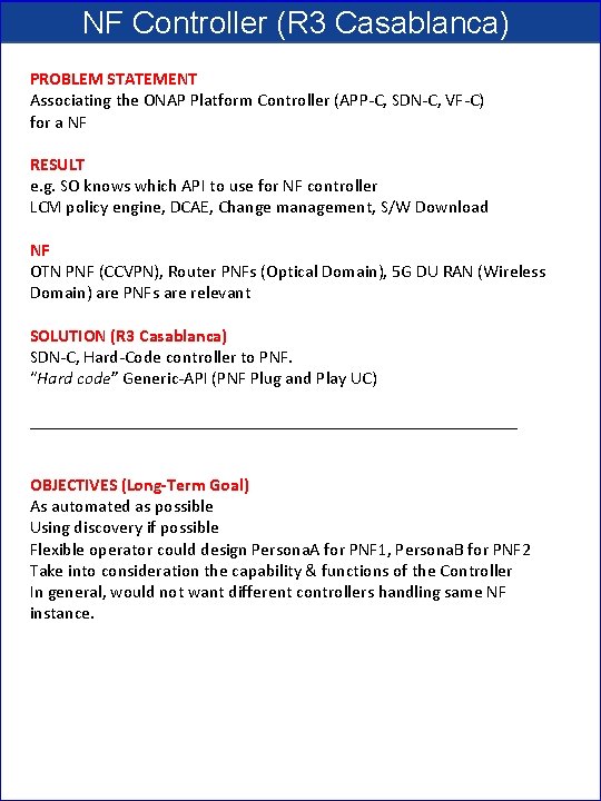
NF Controller (R 3 Casablanca) PROBLEM STATEMENT Associating the ONAP Platform Controller (APP-C, SDN-C, VF-C) for a NF RESULT e. g. SO knows which API to use for NF controller LCM policy engine, DCAE, Change management, S/W Download NF OTN PNF (CCVPN), Router PNFs (Optical Domain), 5 G DU RAN (Wireless Domain) are PNFs are relevant SOLUTION (R 3 Casablanca) SDN-C, Hard-Code controller to PNF. “Hard code” Generic-API (PNF Plug and Play UC) ____________________________ OBJECTIVES (Long-Term Goal) As automated as possible Using discovery if possible Flexible operator could design Persona. A for PNF 1, Persona. B for PNF 2 Take into consideration the capability & functions of the Controller In general, would not want different controllers handling same NF instance.
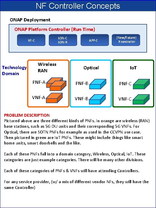
NF Controller Concepts ONAP Deployment ONAP Platform Controller (Run Time) SDN-C SDN-R VF-C Technology Domain Wireless RAN j APP-C Optical [New/Future] X controller Io. T PNF-A PNF-B PNF-C VNF-A VNF-B VNF-C PROBLEM DESCRIPTION Pictured above are three different kinds of PNFs. In orange are wireless (RAN) base stations, such as 5 G DU units and their corresponding 5 G VNFs. For Optical, there are SOTN PNFs for example as used in the CCVPN use case. Then pictured in green are Io. T PNFs. These might include things like smart home units, smart doorbells and the like. Each of these PNFs fall into a domain category, Wireless, Optical, Io. T. These categories are just example categories. There will be many other divisions. Each of these categories of PNFs & VNFs will have attending Controllers. For any service provider, (w/ a mix of different vendor NFs, they will have the same Controller)
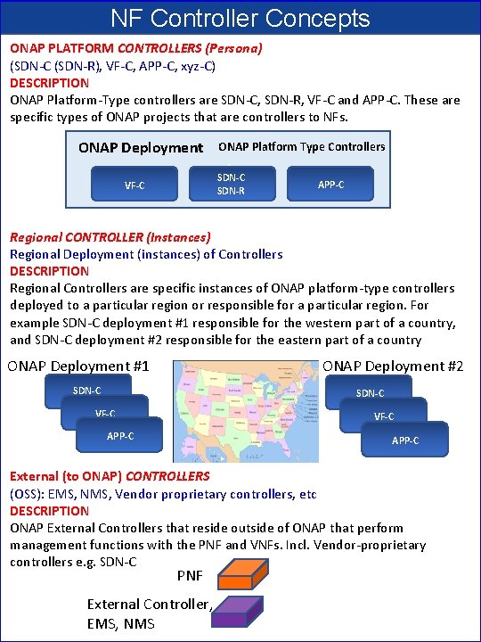
NF Controller Concepts ONAP PLATFORM CONTROLLERS (Persona) (SDN-C (SDN-R), VF-C, APP-C, xyz-C) DESCRIPTION ONAP Platform-Type controllers are SDN-C, SDN-R, VF-C and APP-C. These are specific types of ONAP projects that are controllers to NFs. ONAP Deployment ONAP Platform Type Controllers j SDN-C SDN-R VF-C APP-C Regional CONTROLLER (Instances) Regional Deployment (instances) of Controllers DESCRIPTION Regional Controllers are specific instances of ONAP platform-type controllers deployed to a particular region or responsible for a particular region. For example SDN-C deployment #1 responsible for the western part of a country, and SDN-C deployment #2 responsible for the eastern part of a country ONAP Deployment #1 ONAP Deployment #2 SDN-C VF-C APP-C External (to ONAP) CONTROLLERS (OSS): EMS, NMS, Vendor proprietary controllers, etc DESCRIPTION ONAP External Controllers that reside outside of ONAP that perform management functions with the PNF and VNFs. Incl. Vendor-proprietary controllers e. g. SDN-C PNF External Controller, EMS, NMS
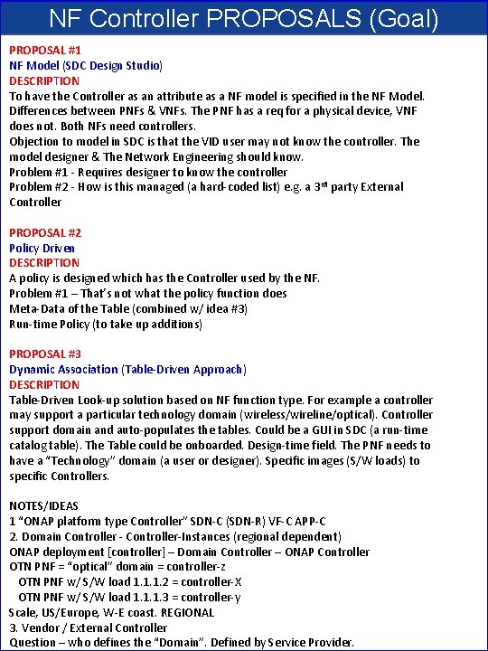
NF Controller PROPOSALS (Goal) PROPOSAL #1 NF Model (SDC Design Studio) DESCRIPTION To have the Controller as an attribute as a NF model is specified in the NF Model. Differences between PNFs & VNFs. The PNF has a req for a physical device, VNF does not. Both NFs need controllers. Objection to model in SDC is that the VID user may not know the controller. The model designer & The Network Engineering should know. Problem #1 - Requires designer to know the controller Problem #2 - How is this managed (a hard-coded list) e. g. a 3 rd party External Controller PROPOSAL #2 Policy Driven DESCRIPTION A policy is designed which has the Controller used by the NF. Problem #1 – That’s not what the policy function does Meta-Data of the Table (combined w/ idea #3) Run-time Policy (to take up additions) PROPOSAL #3 Dynamic Association (Table-Driven Approach) DESCRIPTION Table-Driven Look-up solution based on NF function type. For example a controller may support a particular technology domain (wireless/wireline/optical). Controller support domain and auto-populates the tables. Could be a GUI in SDC (a run-time catalog table). The Table could be onboarded. Design-time field. The PNF needs to have a “Technology” domain (a user or designer). Specific images (S/W loads) to specific Controllers. NOTES/IDEAS 1 “ONAP platform type Controller” SDN-C (SDN-R) VF-C APP-C 2. Domain Controller - Controller-Instances (regional dependent) ONAP deployment [controller] – Domain Controller – ONAP Controller OTN PNF = “optical” domain = controller-z OTN PNF w/ S/W load 1. 1. 1. 2 = controller-X OTN PNF w/ S/W load 1. 1. 1. 3 = controller-y Scale, US/Europe, W-E coast. REGIONAL 3. Vendor / External Controller Question – who defines the “Domain”. Defined by Service Provider.
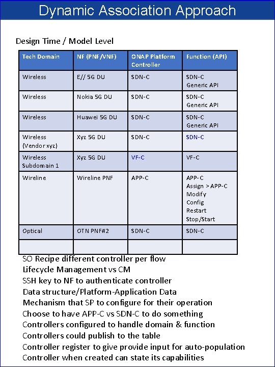
Dynamic Association Approach Design Time / Model Level Tech Domain NF (PNF/VNF) ONAP Platform Controller Function (API) Wireless E// 5 G DU SDN-C Generic API Wireless Nokia 5 G DU SDN-C Generic API Wireless Huawei 5 G DU SDN-C Generic API Wireless (Vendor xyz) Xyz 5 G DU SDN-C Wireless Subdomain 1 Xyz 5 G DU VF-C Wireline PNF APP-C Assign > APP-C Modify Config Restart Stop/Start Optical OTN PNF#2 SDN-C SO Recipe different controller per flow Lifecycle Management vs CM SSH key to NF to authenticate controller Data structure/Platform-Application Data Mechanism that SP to configure for their operation Choose to have APP-C vs SDN-C to do something Controllers configured to handle domain & function Controllers could publish to the table Controller register to give provide input for auto-population Controller when created can state its capabilities
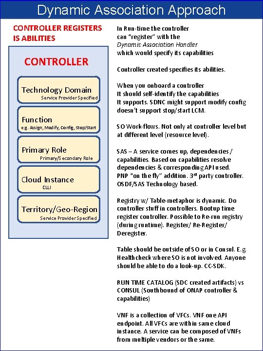
Dynamic Association Approach CONTROLLER REGISTERS IS ABILITIES CONTROLLER Technology Domain Service Provider Specified Function e. g. Assign, Modify, Config, Stop/Start Primary Role Primary/Secondary Role Cloud Instance CLLI Territory/Geo-Region Service Provider Specified In Run-time the controller can “register” with the Dynamic Association Handler which would specify its capabilities Controller created specifies its abilities. When you onboard a controller It should self-identify the capabilities It supports. SDNC might support modify config doesn’t support stop/start LCM. SO Work-flows. Not only at controller level but at different level (resource level). SAS – A service comes up, dependencies / capabilities. Based on capabilities resolve dependencies & corresponding API used. PNP “on the fly” addition. 3 rd party controller. OSDF/SAS Technology based. Registry w/ Table-metaphor is dynamic. Do controller stuff in controllers. Bootup time register controller. Possible to Re-run registry (during runtime). Register/ Re-Register/ Deregister. Table should be outside of SO or in Consul. E. g. Healthcheck where SO is not involved. Anyone should be able to do a look-up. CC-SDK. RUN TIME CATALOG (SDC created artifacts) vs CONSUL (Southbound of ONAP controller & capabilities) VNF is a collection of VFCs. VNF one API endpoint. All VFCs are within same cloud instance. A service can be composed of VNFs from multiple vendors or the same.
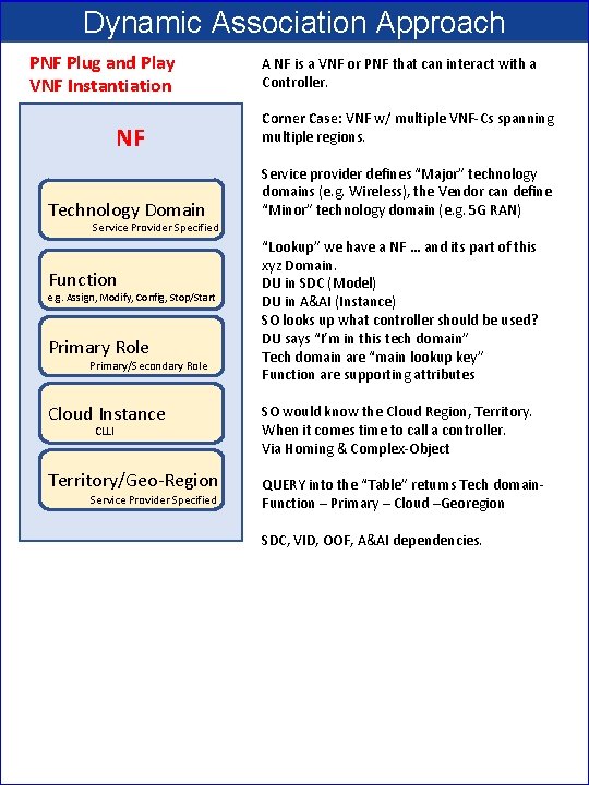
Dynamic Association Approach PNF Plug and Play VNF Instantiation A NF is a VNF or PNF that can interact with a Controller. NF Corner Case: VNF w/ multiple VNF-Cs spanning multiple regions. Technology Domain Service provider defines “Major” technology domains (e. g. Wireless), the Vendor can define “Minor” technology domain (e. g. 5 G RAN) Service Provider Specified Function e. g. Assign, Modify, Config, Stop/Start Primary Role Primary/Secondary Role “Lookup” we have a NF … and its part of this xyz Domain. DU in SDC (Model) DU in A&AI (Instance) SO looks up what controller should be used? DU says “I’m in this tech domain” Tech domain are “main lookup key” Function are supporting attributes Cloud Instance SO would know the Cloud Region, Territory. When it comes time to call a controller. Via Homing & Complex-Object Territory/Geo-Region QUERY into the “Table” returns Tech domain. Function – Primary – Cloud –Georegion CLLI Service Provider Specified SDC, VID, OOF, A&AI dependencies.
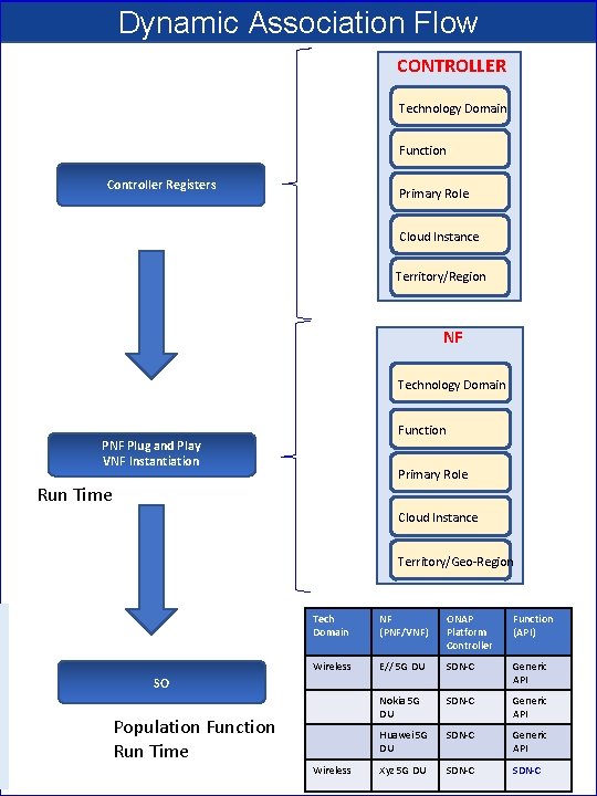
Dynamic Association Flow CONTROLLER Technology Domain Function Controller Registers Primary Role Cloud Instance Territory/Region NF Technology Domain Function PNF Plug and Play VNF Instantiation Primary Role Run Time Cloud Instance Territory/Geo-Region Tech Domain NF (PNF/VNF) ONAP Platform Controller Function (API) Wireless E// 5 G DU SDN-C Generic API Nokia 5 G DU SDN-C Generic API Huawei 5 G DU SDN-C Generic API Xyz 5 G DU SDN-C SO Population Function Run Time Wireless
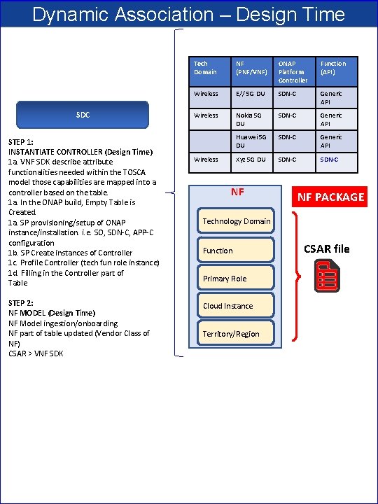
Dynamic Association – Design Time SDC STEP 1: INSTANTIATE CONTROLLER (Design Time) 1 a. VNF SDK describe attribute functionalities needed within the TOSCA model those capabilities are mapped into a controller based on the table. 1 a. In the ONAP build, Empty Table is Created. 1 a. SP provisioning/setup of ONAP instance/installation. i. e. SO, SDN-C, APP-C configuration 1 b. SP Create instances of Controller 1 c. Profile Controller (tech fun role instance) 1 d. Filling in the Controller part of Table. STEP 2: NF MODEL (Design Time) NF Model ingestion/onboarding NF part of table updated (Vendor Class of NF) CSAR > VNF SDK Tech Domain NF (PNF/VNF) ONAP Platform Controller Function (API) Wireless E// 5 G DU SDN-C Generic API Wireless Nokia 5 G DU SDN-C Generic API Huawei 5 G DU SDN-C Generic API Xyz 5 G DU SDN-C Wireless NF NF PACKAGE Technology Domain Function Primary Role Cloud Instance Territory/Region CSAR file
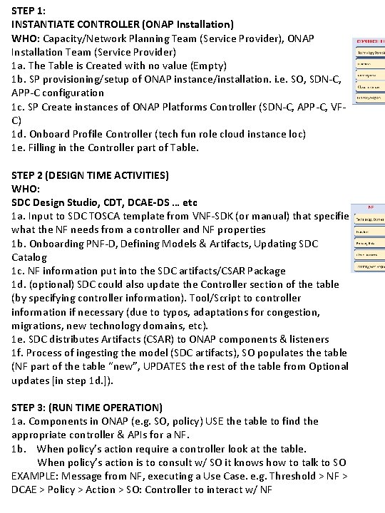
STEP 1: INSTANTIATE CONTROLLER (ONAP Installation) WHO: Capacity/Network Planning Team (Service Provider), ONAP Installation Team (Service Provider) 1 a. The Table is Created with no value (Empty) 1 b. SP provisioning/setup of ONAP instance/installation. i. e. SO, SDN-C, APP-C configuration 1 c. SP Create instances of ONAP Platforms Controller (SDN-C, APP-C, VFC) 1 d. Onboard Profile Controller (tech fun role cloud instance loc) 1 e. Filling in the Controller part of Table. STEP 2 (DESIGN TIME ACTIVITIES) WHO: SDC Design Studio, CDT, DCAE-DS … etc 1 a. Input to SDC TOSCA template from VNF-SDK (or manual) that specifies what the NF needs from a controller and NF properties 1 b. Onboarding PNF-D, Defining Models & Artifacts, Updating SDC Catalog 1 c. NF information put into the SDC artifacts/CSAR Package 1 d. (optional) SDC could also update the Controller section of the table (by specifying controller information). Tool/Script to controller information if necessary (due to typos, adaptations for congestion, migrations, new technology domains, etc). 1 e. SDC distributes Artifacts (CSAR) to ONAP components & listeners 1 f. Process of ingesting the model (SDC artifacts), SO populates the table (NF part of the table “new”, UPDATES the rest of the table from Optional updates [in step 1 d. ]). STEP 3: (RUN TIME OPERATION) 1 a. Components in ONAP (e. g. SO, policy) USE the table to find the appropriate controller & APIs for a NF. 1 b. When policy’s action require a controller look at the table. When policy’s action is to consult w/ SO it knows how to talk to SO EXAMPLE: Message from NF, executing a Use Case. e. g. Threshold > NF > DCAE > Policy > Action > SO: Controller to interact w/ NF
DISCUSSION NOTE: Once initial instantiation takes place & mapping, that mapping needs to be maintained for the lifecycle of the NF. Q: Stability of Table? Will answers change? A: For same data in will get same answer out. A: Updates to the table can be made Q: (Ben) case: conflict race condition (operator#1 updating / operator#2 updating table). A: Transaction control ONAP installation team updates. Should own data integrity of the table. Maria DB transaction control. Q: (Oskar) case: granularity of look-up, look-up based on a specific action. Restart but can’t do config modify. For a particular instance of NF handled by one controller instances. Cases w/ dynamic look-up hard to guarantee. If you have granularity on operation-level get two answers depending on which operation you want to perform. Locking in A&AI to block other things. Operations lock out ONAP from doing changes while maintenance Course locking/ Finer locking (future) NF#12 two active Policies Policy #1 Restart Policy #2 Config-Modify. Trigger at same time. Table lookup > Get Controller Instances.
NF Controller PROPOSALS (Goal) DESIGN-TIME SDC – Design Studio Onboard a resource (type, role, function, [tech domain]) Deduce tech domain? From type-role-function? Operator specifies the Technology Domain of the NF Operator specified the Technology domains (or possibly Techdomain is deduced from type-role-function) Service Provider defines the possible Technology Domains Assign every NE and Service to a Technology Domain TD 1 = SDN-C TD 2 = VF-C manually modeled, table created. Tech. Domain to ONAPPlatform. Controller SDC – Model “mapping” > Catalog RUN-TIME As a NF registers, the (managing ONAP entity e. g. SO for PNF) would look up the TD > OPC mapping) 3 Technology Controllers (Wireless, Enterprise, Other) When generate controller it populates the table. Dynamically populate table
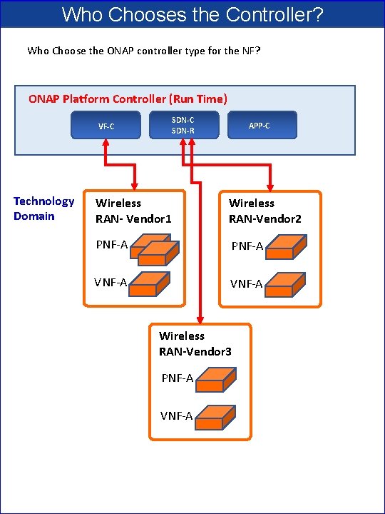
Who Chooses the Controller? Who Choose the ONAP controller type for the NF? ONAP Platform Controller (Run Time) SDN-C j SDN-R VF-C Technology Domain APP-C Wireless RAN- Vendor 1 Wireless RAN-Vendor 2 PNF-A VNF-A Wireless RAN-Vendor 3 PNF-A VNF-A
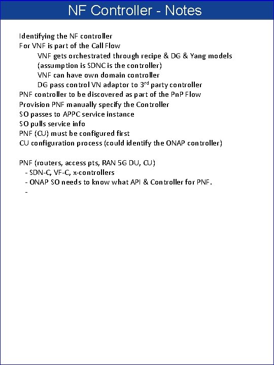
NF Controller - Notes Identifying the NF controller For VNF is part of the Call Flow VNF gets orchestrated through recipe & DG & Yang models (assumption is SDNC is the controller) VNF can have own domain controller DG pass control VN adaptor to 3 rd party controller PNF controller to be discovered as part of the Pn. P Flow Provision PNF manually specify the Controller SO passes to APPC service instance SO pulls service info PNF (CU) must be configured first CU configuration process (could identify the ONAP controller) PNF (routers, access pts, RAN 5 G DU, CU) - SDN-C, VF-C, x-controllers - ONAP SO needs to know what API & Controller for PNF. -
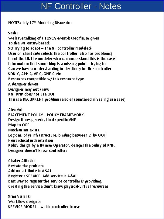
NF Controller - Notes NOTES: July 17 th Modeling Discussion Seshu We have talking of a TOSCA event-based flavor given To the WF entity-based; SO Trying to adapt – The NF controller modeled. User on client side selects the controller (also has problems) If not the UI, the modeler who can understand this is the case Information that something is a missing point – trying to Can we have a understanding in des-time; for the controller SDN-C, APP-C, VF-C, GNF-C etc Resources compatible w/ this resource type A designer driven Designer may not know PNF PNP does not use OOF This is a RECURRENT problem (also encountered in Scaling use case) Alex Vul PLACEMENT POLICY – POLICY FRAMEWORK Design times generic, bind specific VNF Map to OOF. Mechanism exists. Log des; phys infrastructure; binding between 2 (by OOF) Heirarchical orchestration Policy design by a Human Operator, designs the policy of PNF. Designer doesn’t know controller; Chaker Al. Hakim Restate the problem Add an attribute in A&AI Register a SERVICE. Add service in A&AI. Best way to register the service controller is providing. Creating the service don’t know physical/virtual resources. Srini Vellanki Workflow designer SERVICE MODEL – which controller to use
A&AI (Reference) • ONAP and PNF Plug and Play for 5 G RAN • 5 G Use Case Team
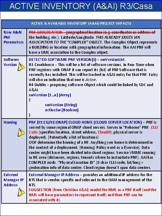
ACTIVE INVENTORY (A&AI) R 3/Casa ACTIVE & AVAILABLE INVENTORY (A&AI) PROJECT IMPACTS New A&AI PNF Parameters PNF GEOLOCATION - geographical location (e. g. coordinates or address of the building, etc. ). Latitude/Longitude. THIS ALREADY EXISTS VIA ASSOCIATION TO THE “COMPLEX” OBJECT. The Complex Object represents a BUILDING or location with geographical information. The AAI PNF will have a UML association to the Complex object. Software Version DETECTED SOFTWARE PNF VERSION(S) – sw. Version. List. R 3 Casablanca – This will be a list of software versions. In Run-Time when PNF registers with ONAP it can report its (list) of PNF Software that is currently has installed. This will be tracked in A&AI entry for that PNF. Entry will also an indication that one is Active. R 4 Dublin – proposing software Object which could be linked by SDC and A&AI. sw. Version [1…x] (Array) { sw. Version (String) active. Sw (Boolean) } Homing PNF [#1: CU/#2: ONAP] CLOUD HOME (CLOUD SERVER LOCATION) – PNF is served by some regional ONAP cloud servers. Serves in “Rehome” PNF. CLLI Code (specifies location, street address, Cloud. ID, physical server is deployed). [Potentially a list of locations] OOF determine the homing of a NF. Anything you home is determined in the context of a deployment. (Homing) Policy used as a f(service). Data center might have been divided into cloud regions. Service VMME running in NE area (distances, regions, tenants where to instantiate PNF). AAI has COMPLEX node. “Physical Location ID” (8 char CLLI code, lat/long = geolocation info of data center. Cloud region doesn’t span data centers. External Manager IP Address – provides an additional IP address for the BTS that is vendor-specific and relevant to the OAM management of the BTS. SUGGESTION (from Christina A&AI) model the NMS as a PNF itself (and the NMS will have parameters to represent itself; and then PNF can be associated with it).
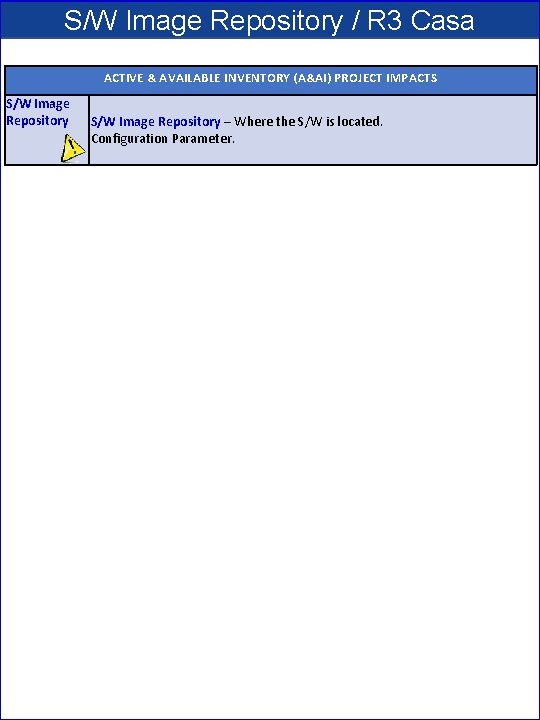
S/W Image Repository / R 3 Casa ACTIVE & AVAILABLE INVENTORY (A&AI) PROJECT IMPACTS S/W Image Repository – Where the S/W is located. Configuration Parameter.
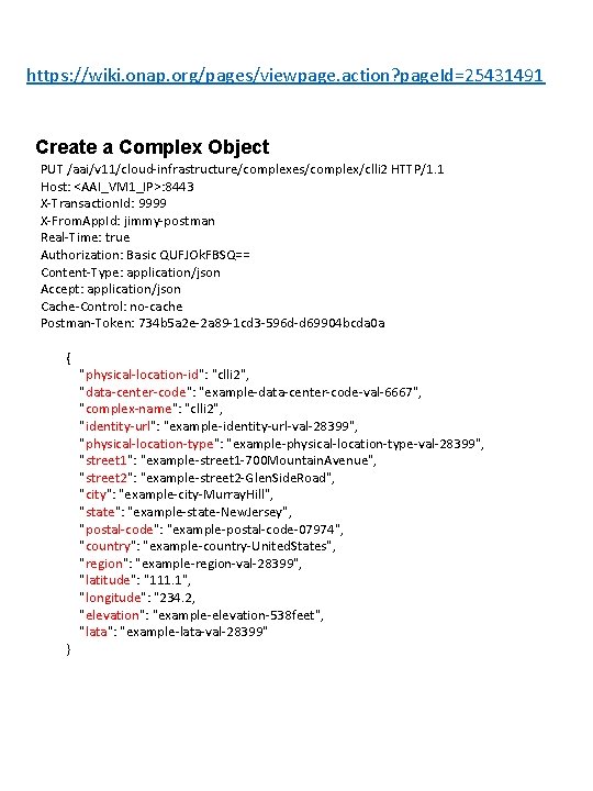
https: //wiki. onap. org/pages/viewpage. action? page. Id=25431491 Create a Complex Object PUT /aai/v 11/cloud-infrastructure/complexes/complex/clli 2 HTTP/1. 1 Host: <AAI_VM 1_IP>: 8443 X-Transaction. Id: 9999 X-From. App. Id: jimmy-postman Real-Time: true Authorization: Basic QUFJOk. FBSQ== Content-Type: application/json Accept: application/json Cache-Control: no-cache Postman-Token: 734 b 5 a 2 e-2 a 89 -1 cd 3 -596 d-d 69904 bcda 0 a { "physical-location-id": "clli 2", "data-center-code": "example-data-center-code-val-6667", "complex-name": "clli 2", "identity-url": "example-identity-url-val-28399", "physical-location-type": "example-physical-location-type-val-28399", "street 1": "example-street 1 -700 Mountain. Avenue", "street 2": "example-street 2 -Glen. Side. Road", "city": "example-city-Murray. Hill", "state": "example-state-New. Jersey", "postal-code": "example-postal-code-07974", "country": "example-country-United. States", "region": "example-region-val-28399", "latitude": "111. 1", "longitude": "234. 2, "elevation": "example-elevation-538 feet", "lata": "example-lata-val-28399" }
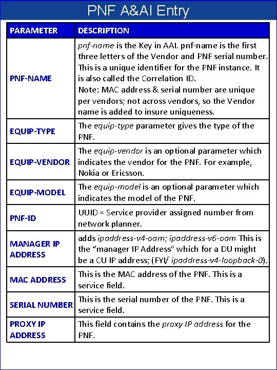
PNF A&AI Entry PARAMETER DESCRIPTION PNF-NAME pnf-name is the Key in AAI. pnf-name is the first three letters of the Vendor and PNF serial number. This is a unique identifier for the PNF instance. It is also called the Correlation ID. Note: MAC address & serial number are unique per vendors; not across vendors, so the Vendor name is added to insure uniqueness. EQUIP-TYPE The equip-type parameter gives the type of the PNF. The equip-vendor is an optional parameter which EQUIP-VENDOR indicates the vendor for the PNF. For example, Nokia or Ericsson. EQUIP-MODEL The equip-model is an optional parameter which indicates the model of the PNF-ID UUID = Service provider assigned number from network planner. MANAGER IP ADDRESS adds ipaddress-v 4 -oam; ipaddress-v 6 -oam This is the “manager IP Address” which for a DU might be a CU IP address; (FYI/ ipaddress-v 4 -loopback-0). MAC ADDRESS This is the MAC address of the PNF. This is a service field. SERIAL NUMBER This is the serial number of the PNF. This is a service field. PROXY IP ADDRESS This field contains the proxy IP address for the PNF.
PNF Plug and Play ROADMAP (After Casablanca) • ONAP and PNF Plug and Play for 5 G RAN • 5 G Use Case Team
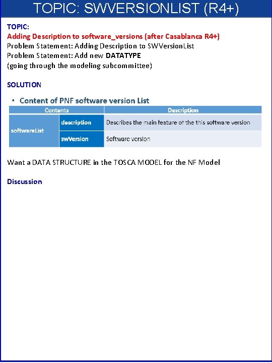
TOPIC: SWVERSIONLIST (R 4+) TOPIC: Adding Description to software_versions (after Casablanca R 4+) Problem Statement: Adding Description to SWVersion. List Problem Statement: Add new DATATYPE (going through the modeling subcommittee) SOLUTION Want a DATA STRUCTURE in the TOSCA MODEL for the NF Model Discussion
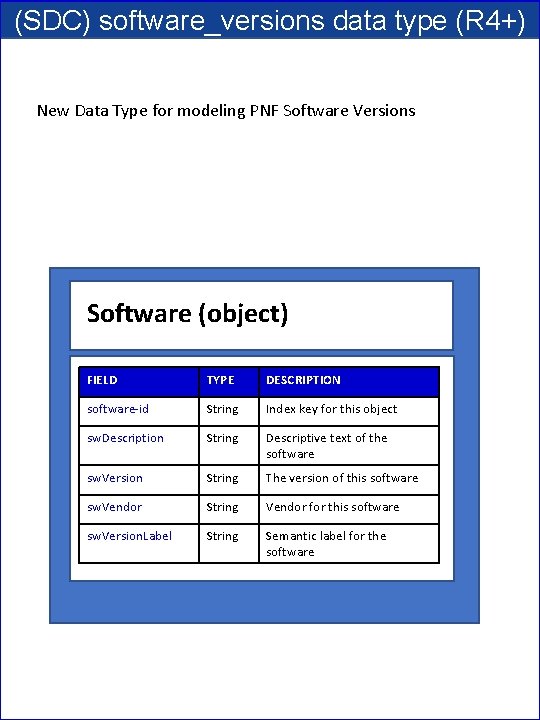
(SDC) software_versions data type (R 4+) New Data Type for modeling PNF Software Versions Software (object) FIELD TYPE DESCRIPTION software-id String Index key for this object sw. Description String Descriptive text of the software sw. Version String The version of this software sw. Vendor String Vendor for this software sw. Version. Label String Semantic label for the software
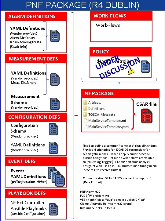
PNF PACKAGE (R 4 DUBLIN) ALARM DEFINITIONS YAML Definitions (Vendor provided) Alarm Dictionary & Sub-tending faults [Static Info] MEASUREMENT DEFS YAML Definitions (Vendor provided) Meas. Dictionary Measurement Schema (Vendor provided) WORK-FLOWS Work-Flows POLICY ER ION D UN USS C S I D Identify Controller NF PACKAGE CSAR file CONFIGURATION DEFS Configuration Schema (Vendor provided) YAML Definitions (Vendor provided) EVENT DEFS Events YAML Definitions (pnf. Registration, HVVes) PLAYBOOK DEFS NF Ext Controller Ansible Playbooks (Ansible Configuration) Need to define a common “template” that all vendors Provide dictionaries for. DCAE-DS responsible for reading these files. Closed Loop. Vendor describe alarms being sent. Definition what alarms correlated to (collecting, triggers). CLAMP performs analysis, design of who uses it is SDC. Holmes monitoring micro -services (to receive alarms). Communication STANDARDS we want to support? [Data Format] PNF Alarm #22 S/W problem xyz VES = fault fields; “fault’ domain publish DMaa. P Clamp, Analytic, Holmes – [#22 event] Dictionary looks up #22 ->
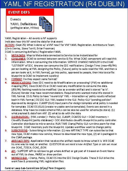
YAML NF REGISTRATION (R 4 DUBLIN) EVENT DEFS Events YAML Definitions (pnf. Registration, HVVes) YAML Registration – All events a NF supports Indicates how this NF send the data for that event ACTION: (Sept 25) What is done w/ a VNF now? for VNF YAML Registration. Architecture Team (Chris Donley, Steve Terrill, Brian Freeman) DCAE is consuming Artifacts / Registration YAML 1. METADATA: Map to Meta-data connected to Service to be instantiated for 2. CONSUMER: DCAE to connect between service & file. What DCAE component will read this information. Who is consuming the information. SERVICE CHANGE HANDLER is the DCAE “LISTENER” of SDC. Anyone can consume the SDC notifications. [Design Time: (now=R 3/R 4) person looking at YML designing the Policy, [future] policy to auto-read the YML and then a person looks at it, in YML format], go into policy, approved by people, then into tosca-file blueprint to DCAE to implement a policy) 3. FORMAT: Do they expect same format? 4. MODIFICATIONS: Does SDC need to do Modifications or processing? [FM] no additional mapping [PM]. Does DCAE-DS or DCAE need any modification to consume the data. [(R 3/R 4) Nothing needs to be modified. Use as a vendor artifact and is stored “as is”. (future) Vendor may have recommendations. Requirements wanted meta-info stored in YML format. DS & Policy to have “round-trip” YML – interaction w/ policy results reflected back in YML format. ] DS SDC GUI. YML loaded in the GUI. Policy-GUI “pending policies”. Approved by designers. CLAMP (GUI) input parms for design template what policy is needed for template. DCAE-DS (GUI) [create re-usable service template]. Events are stored in a database. May have to create schema YMLs can be also be used for schema (to store). (1) what payload & data from x. NF. (2) what to do with the data. 5. DISTRIBUTION - [YML vendor] > Policy GUI, CLAMP, DCAEDS GUI > DCAE Inventory > Cloudify Blueprint [policy database] > SDC distributes cloudify blueprint to policy controller. Controller distribute to micro-service. RUN TIME Clamp/Policy GUI run-time parm for that blueprint. DCAE Inventory pulls the blueprint. Update workflow want to change policy. 6. SUBSCRIBING - Subscribing to information. (1) new ARTIFACT TYPE can subscribe to that new type, DCAE makes new service, knows to download the new type, (2) all is packaged in the CSAR package. 7. ARTIFACT TYPE: Application that receives the artifact needs to know what it is. Will DCAE try one way to read, or another. QUESTION do we need a new Artifact Type or can we reuse the DCAE_TOSCA, DCAE_JSON. 8. API - SUPPORT API to retrieve to get whole Artifact or get part of it based on Event Name out of YML to show, PARSE or show portion. 9. MERGED GUI – Clamp, Policy, DCAE DS into the SDC Design Studio. These 3 GUI drive the work flow & processing YML registration files. Control Loop Sub-Committee (Vijay/ Pam Dragosh)
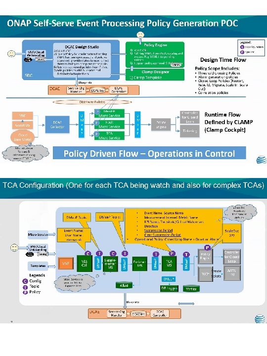
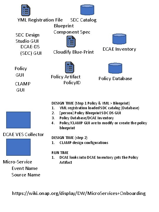
YML Registration File SDC Catalog Blueprint Component Spec SDC Design Studio GUI DCAE-DS Cloudify Blue-Print (SDC) GUI Policy GUI CLAMP GUI Policy Artifact Policy. ID DCAE Inventory Policy Database DESIGN TIME (Step 1 Policy & YML > Blueprint) 1. YML registration loaded SDC catalog (Database) 2. [person] Policy Blueprint SDC DS GUI 3. Policy Database/DCAE Inventory 4. Policy/CLAMP GUI are to modify or create the policy blueprint DCAE VES Collector Micro-Service Event Name Source Name DESIGN TIME (step 2) 1. CLAMP design configurations RUN TIME 1. DCAE looks into DCAE Inventory gets the Policy Artifact https: //wiki. onap. org/display/DW/Micro. Services+Onboarding
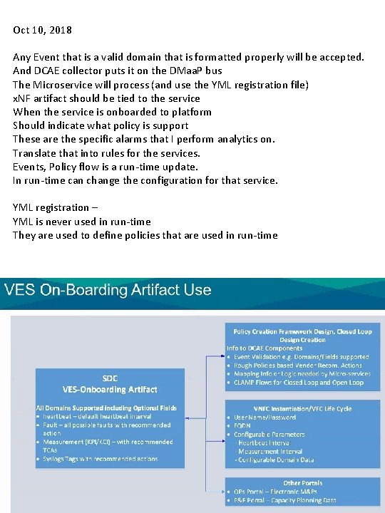
Oct 10, 2018 Any Event that is a valid domain that is formatted properly will be accepted. And DCAE collector puts it on the DMaa. P bus The Microservice will process (and use the YML registration file) x. NF artifact should be tied to the service When the service is onboarded to platform Should indicate what policy is support These are the specific alarms that I perform analytics on. Translate that into rules for the services. Events, Policy flow is a run-time update. In run-time can change the configuration for that service. YML registration – YML is never used in run-time They are used to define policies that are used in run-time
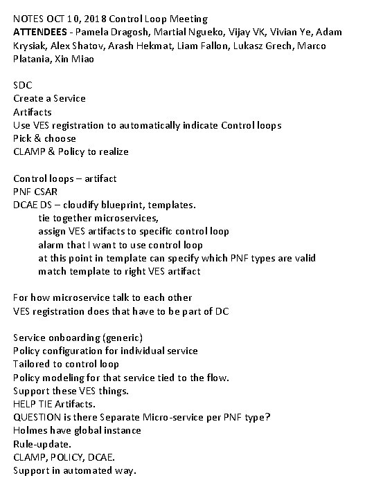
NOTES OCT 10, 2018 Control Loop Meeting ATTENDEES - Pamela Dragosh, Martial Ngueko, Vijay VK, Vivian Ye, Adam Krysiak, Alex Shatov, Arash Hekmat, Liam Fallon, Lukasz Grech, Marco Platania, Xin Miao SDC Create a Service Artifacts Use VES registration to automatically indicate Control loops Pick & choose CLAMP & Policy to realize Control loops – artifact PNF CSAR DCAE DS – cloudify blueprint, templates. tie together microservices, assign VES artifacts to specific control loop alarm that I want to use control loop at this point in template can specify which PNF types are valid match template to right VES artifact For how microservice talk to each other VES registration does that have to be part of DC Service onboarding (generic) Policy configuration for individual service Tailored to control loop Policy modeling for that service tied to the flow. Support these VES things. HELP TIE Artifacts. QUESTION is there Separate Micro-service per PNF type? Holmes have global instance Rule-update. CLAMP, POLICY, DCAE. Support in automated way.
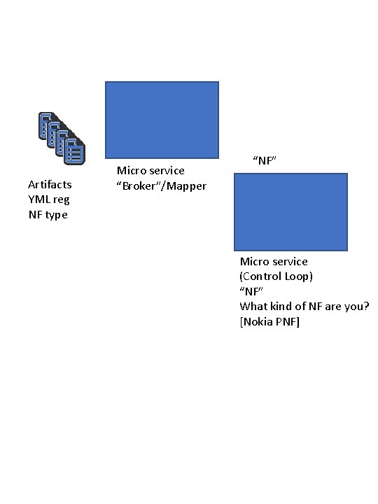
Artifacts YML reg NF type Micro service “Broker”/Mapper “NF” Micro service (Control Loop) “NF” What kind of NF are you? [Nokia PNF]
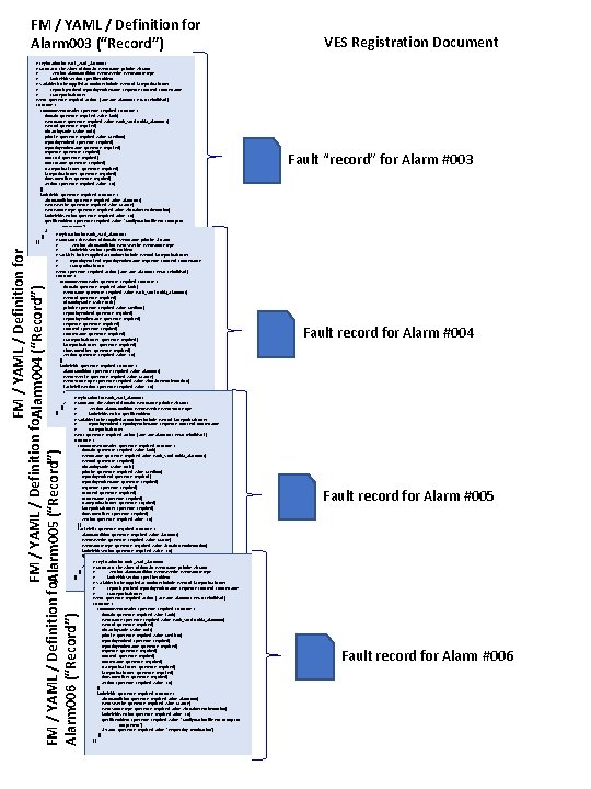
FM / YAML / Definition for Alarm 003 (“Record”) FM / YAML / Definition for. Alarm 004 (“Record”) FM / YAML / Definition for. Alarm 005 (“Record”) Alarm 006 (“Record”) # registration for Fault_v. Mrf_alarm 003 # Constants: the values of domain, event. Name, priority, vfstatus # , version, alarm. Condition, event. Severity, event. Source. Type, # fault. Fields. Version, specific. Problem, # Variables (to be supplied at runtime) include: event. Id, last. Epoch. Microsec, # reporting. Entity. Id, reporting. Entity. Name, sequence, source. Id, source. Name, # start. Epoch. Microsec event: {presence: required, action: [ any, alarm 003, RECO-rebuild. Vnf ], structure: { common. Event. Header: {presence: required, structure: { domain: {presence: required, value: fault}, event. Name: {presence: required, value: Fault_Vmrf-Nokia_Alarm 003}, event. Id: {presence: required}, nf. Naming. Code: {value: mrfx}, priority: {presence: required, value: Medium}, reporting. Entity. Id: {presence: required}, reporting. Entity. Name: {presence: required}, sequence: {presence: required}, source. Id: {presence: required}, source. Name: {presence: required}, start. Epoch. Microsec: {presence: required}, last. Epoch. Microsec: {presence: required}, time. Zone. Offset: {presence: required}, version: {presence: required, value: 3. 0} }}, fault. Fields: {presence: required, structure: { alarm. Condition: {presence: required, value: alarm 003}, event. Severity: {presence: required, value: MAJOR}, event. Source. Type: {presence: required, value: virtual. Network. Function}, fault. Fields. Version: {presence: required, value: 3. 0}, specific. Problem: {presence: required, value: "Configuration file was corrupt or not present"}, vf. Status: {presence: required, value: "Requesting Termination"} # registration for Fault_v. Mrf_alarm 003 }} # Constants: the values of domain, event. Name, priority, vfstatus }} # , version, alarm. Condition, event. Severity, event. Source. Type, # fault. Fields. Version, specific. Problem, # Variables (to be supplied at runtime) include: event. Id, last. Epoch. Microsec, # reporting. Entity. Id, reporting. Entity. Name, sequence, source. Id, source. Name, # start. Epoch. Microsec event: {presence: required, action: [ any, alarm 003, RECO-rebuild. Vnf ], structure: { common. Event. Header: {presence: required, structure: { domain: {presence: required, value: fault}, event. Name: {presence: required, value: Fault_Vmrf-Nokia_Alarm 003}, event. Id: {presence: required}, nf. Naming. Code: {value: mrfx}, priority: {presence: required, value: Medium}, reporting. Entity. Id: {presence: required}, reporting. Entity. Name: {presence: required}, sequence: {presence: required}, source. Id: {presence: required}, source. Name: {presence: required}, start. Epoch. Microsec: {presence: required}, last. Epoch. Microsec: {presence: required}, time. Zone. Offset: {presence: required}, version: {presence: required, value: 3. 0} }}, fault. Fields: {presence: required, structure: { alarm. Condition: {presence: required, value: alarm 003}, event. Severity: {presence: required, value: MAJOR}, event. Source. Type: {presence: required, value: virtual. Network. Function}, fault. Fields. Version: {presence: required, value: 3. 0}, specific. Problem: {presence: required, value: "Configuration file was corrupt or not present"}, # registration for Fault_v. Mrf_alarm 003 vf. Status: {presence: required, value: "Requesting Termination"} # Constants: the values of domain, event. Name, priority, vfstatus }} # , version, alarm. Condition, event. Severity, event. Source. Type, }} # fault. Fields. Version, specific. Problem, # Variables (to be supplied at runtime) include: event. Id, last. Epoch. Microsec, # reporting. Entity. Id, reporting. Entity. Name, sequence, source. Id, source. Name, # start. Epoch. Microsec event: {presence: required, action: [ any, alarm 003, RECO-rebuild. Vnf ], structure: { common. Event. Header: {presence: required, structure: { domain: {presence: required, value: fault}, event. Name: {presence: required, value: Fault_Vmrf-Nokia_Alarm 003}, event. Id: {presence: required}, nf. Naming. Code: {value: mrfx}, priority: {presence: required, value: Medium}, reporting. Entity. Id: {presence: required}, reporting. Entity. Name: {presence: required}, sequence: {presence: required}, source. Id: {presence: required}, source. Name: {presence: required}, start. Epoch. Microsec: {presence: required}, last. Epoch. Microsec: {presence: required}, time. Zone. Offset: {presence: required}, version: {presence: required, value: 3. 0} }}, fault. Fields: {presence: required, structure: { alarm. Condition: {presence: required, value: alarm 003}, event. Severity: {presence: required, value: MAJOR}, event. Source. Type: {presence: required, value: virtual. Network. Function}, fault. Fields. Version: {presence: required, value: 3. 0}, specific. Problem: {presence: required, value: "Configuration file was corrupt or not present"}, # registration for Fault_v. Mrf_alarm 006 vf. Status: {presence: required, value: "Requesting Termination"} # Constants: the values of domain, event. Name, priority, vfstatus }} # , version, alarm. Condition, event. Severity, event. Source. Type, }} # fault. Fields. Version, specific. Problem, # Variables (to be supplied at runtime) include: event. Id, last. Epoch. Microsec, # reporting. Entity. Id, reporting. Entity. Name, sequence, source. Id, source. Name, # start. Epoch. Microsec event: {presence: required, action: [ any, alarm 003, RECO-rebuild. Vnf ], structure: { common. Event. Header: {presence: required, structure: { domain: {presence: required, value: fault}, event. Name: {presence: required, value: Fault_Vmrf-Nokia_Alarm 006}, event. Id: {presence: required}, nf. Naming. Code: {value: mrfx}, priority: {presence: required, value: Medium}, reporting. Entity. Id: {presence: required}, reporting. Entity. Name: {presence: required}, sequence: {presence: required}, source. Id: {presence: required}, source. Name: {presence: required}, start. Epoch. Microsec: {presence: required}, last. Epoch. Microsec: {presence: required}, time. Zone. Offset: {presence: required}, version: {presence: required, value: 3. 0} }}, fault. Fields: {presence: required, structure: { alarm. Condition: {presence: required, value: alarm 006}, event. Severity: {presence: required, value: MAJOR}, event. Source. Type: {presence: required, value: virtual. Network. Function}, fault. Fields. Version: {presence: required, value: 3. 0}, specific. Problem: {presence: required, value: "Configuration file was corrupt or not present"}, vf. Status: {presence: required, value: "Requesting Termination"} }} }} VES Registration Document Fault “record” for Alarm #003 Fault record for Alarm #004 Fault record for Alarm #005 Fault record for Alarm #006
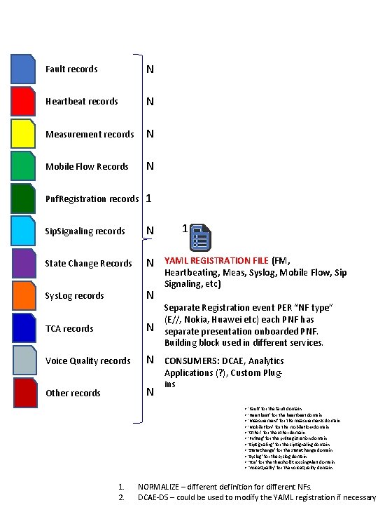
Fault records N Heartbeat records N Measurement records N Mobile Flow Records N Pnf. Registration records 1 Sip. Signaling records N State Change Records N Sys. Log records N TCA records N Voice Quality records N Other records N 1 YAML REGISTRATION FILE (FM, Heartbeating, Meas, Syslog, Mobile Flow, Sip Signaling, etc) Separate Registration event PER “NF type” (E//, Nokia, Huawei etc) each PNF has separate presentation onboarded PNF. Building block used in different services. CONSUMERS: DCAE, Analytics Applications (? ), Custom Plugins • ‘Fault’ for the fault domain • ‘Heartbeat’ for the heartbeat domain • ‘Measurement’ for the measurements domain • ‘Mobile. Flow’ for the mobile. Flow domain • ‘Other’ for the other domain • ‘Pnf. Reg’ for the pnf. Registration domain • ‘Sip. Signaling’ for the sip. Signaling domain • ‘State. Change’ for the state. Change domain • ‘Syslog’ for the syslog domain • ‘Tca’ for the threshold. Crossing. Alert domain • ‘Voice. Quality’ for the voice. Quality domain 1. 2. NORMALIZE – different definition for different NFs. DCAE-DS – could be used to modify the YAML registration if necessary
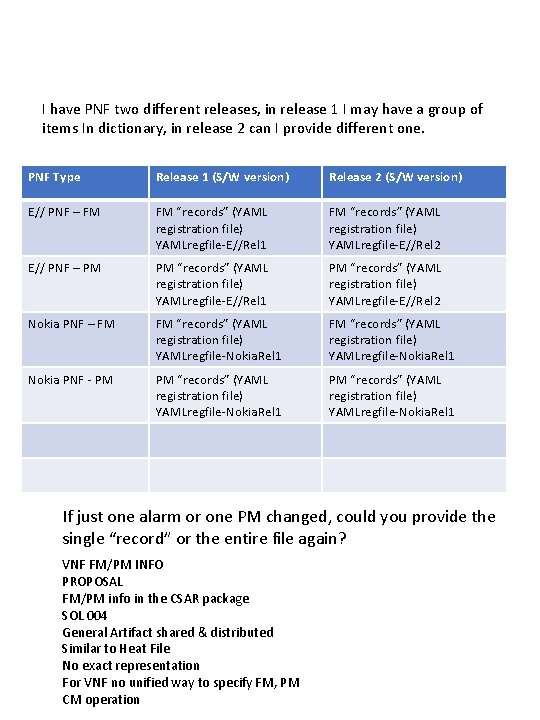
I have PNF two different releases, in release 1 I may have a group of items In dictionary, in release 2 can I provide different one. PNF Type Release 1 (S/W version) Release 2 (S/W version) E// PNF – FM FM “records” (YAML registration file) YAMLregfile-E//Rel 1 FM “records” (YAML registration file) YAMLregfile-E//Rel 2 E// PNF – PM PM “records” (YAML registration file) YAMLregfile-E//Rel 1 PM “records” (YAML registration file) YAMLregfile-E//Rel 2 Nokia PNF – FM FM “records” (YAML registration file) YAMLregfile-Nokia. Rel 1 Nokia PNF - PM PM “records” (YAML registration file) YAMLregfile-Nokia. Rel 1 If just one alarm or one PM changed, could you provide the single “record” or the entire file again? VNF FM/PM INFO PROPOSAL FM/PM info in the CSAR package SOL 004 General Artifact shared & distributed Similar to Heat File No exact representation For VNF no unified way to specify FM, PM CM operation

Model#1001 Nokia PNF PACKAGE CSAR file Model#1002 YAML REGISTRATION FILE Nokia PNF E// PNF PACKAGE CSAR file YAML REGISTRATION FILE E// PNF Huawei PNF PACKAGE CSAR file YAML REGISTRATION FILE Huawei PNF Nokia VNF PACKAGE CSAR file YAML REGISTRATION FILE Nokia VNF E// VNF PACKAGE CSAR file YAML REGISTRATION FILE E// VNF Huawei VNF PACKAGE CSAR file YAML REGISTRATION FILE Huawei VNF
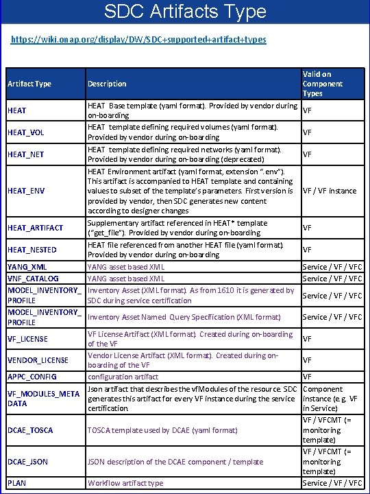
SDC Artifacts Type https: //wiki. onap. org/display/DW/SDC+supported+artifact+types Artifact Type Description HEAT Base template (yaml format). Provided by vendor during on-boarding HEAT template defining required volumes (yaml format). HEAT_VOL Provided by vendor during on-boarding HEAT template defining required networks (yaml format). HEAT_NET Provided by vendor during on-boarding (deprecated) HEAT Environment artifact (yaml format, extension “. env”). This artifact is accompanied to HEAT template and containing HEAT_ENV values to subset of the template’s parameters. First version is provided by vendor, then SDC generates new content according to designer changes Supplementary artifact referenced in HEAT* template HEAT_ARTIFACT (“get_file”). Provided by vendor during on-boarding HEAT file referenced from another HEAT file (yaml format). HEAT_NESTED Provided by vendor during on-boarding YANG_XML YANG asset based XML VNF_CATALOG YANG asset based XML MODEL_INVENTORY_ Inventory Asset (XML format). As from 1610 it is generated by PROFILE SDC during service certification MODEL_INVENTORY_ Inventory Asset Named Query Specification (XML format) PROFILE VF License Artifact (XML format). Created during on-boarding VF_LICENSE of the VF Vendor License Artifact (XML format). Created during on. VENDOR_LICENSE boarding of the VF APPC_CONFIG configuration artifact Json artifact that describes the vf. Modules of the resource. SDC VF_MODULES_META generates this artifact for every VF instance during the service DATA certification. HEAT DCAE_TOSCA template used by DCAE (yaml format) DCAE_JSON description of the DCAE component / template PLAN Workflow artifact type Valid on Component Types VF VF / VF instance VF VF Service / VF / VFC VF VF VF Component instance (e. g. VF in Service) VF / VFCMT (= monitoring template) Service / VFC
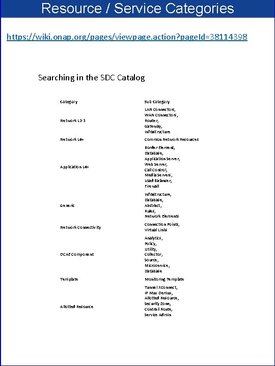
Resource / Service Categories https: //wiki. onap. org/pages/viewpage. action? page. Id=38114398 Searching in the SDC Catalog Category Sub Category Network L 2 -3 LAN Connectors, WAN Connectors, Router, Gateway, Infrastructure Network L 4+ Common Network Resources Application L 4+ Border Element, Database, Application Server, Web Server, Call Control, Media Servers, Load Balancer, Firewall Generic Infrastructure, Database, Abstract, Rules, Network Elements Network Connectivity Connection Points, Virtual Links DCAE Component Analytics, Policy, Utility, Collector, Source, Microservice, Database Template Monitoring Template Allotted Resource Tunnel XConnect, IP Mux Demux, Allotted Resource, Security Zone, Contrail Route, Service Admin
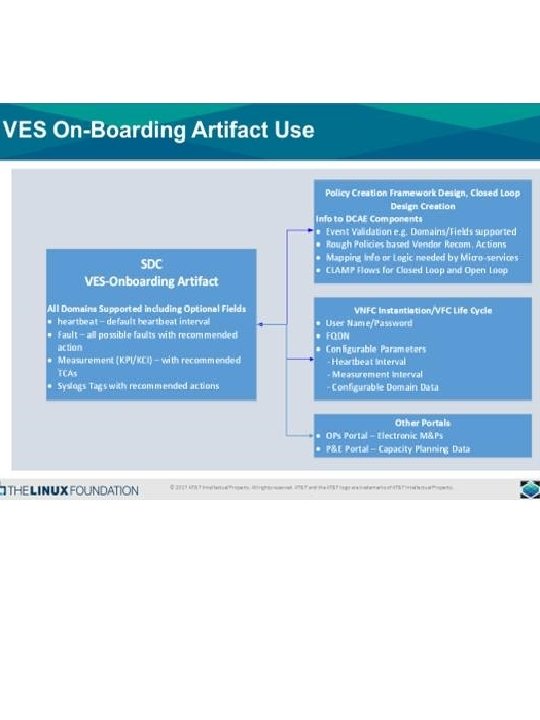
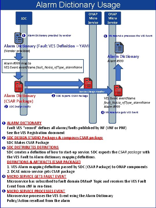
Alarm Dictionary Usage ONAP Micro Service SDC ONAP Micro Service 1 Alarm Dictionary provided by vendor 5 Microservice processes the VES Event Alarm Dictionary (Fault VES Definition – YAML) (Vendor provided) Alarm Dictionary Alarm #999 map to VES Event event. Name fault_Nokia_nf. Type_alarm. Name Alarm Dictionary (CSAR Package) 2 SDC Design Studio Service Change Handler 3 SDC Exports CSAR Package VES Event event. Name fault_Nokia_nf. Type_alarm. Name Alarm #999 4 Microservice gets VES Event 1 2 3 4 5 ALARM DICTIONARY Fault VES “record” defines all alarms/faults published by NF (VNF or PNF) See the VES Registration document SDC DESIGN STUDIO Packages & composes CSAR package SDC Makes CSAR Package SDC DISTRIBUTES DEFINITIONS SDC creates a definition of how to start-up service. SDC exports the CSAR package with the VES Fault to Alarm dictionary mapping definitions. DEFINITIONS & ARTIFACTS (CSAR PACKAGE) 1. VES-Alarm mapping definition passed by SDC (CSAR Package) to ONAP components 2. DCAE micro-service gets CSAR package MICRO SERVICE GETS FAULT EVENT Microservice has subscribed to fault domain DMaa. P Topic and receives the VES Fault Event from x. NF in run-time. MICRO SERVICE PROCESSES EVENT Microservice processes the VES Event using the Alarm Dictionary Policy/Action resultant from the alarm
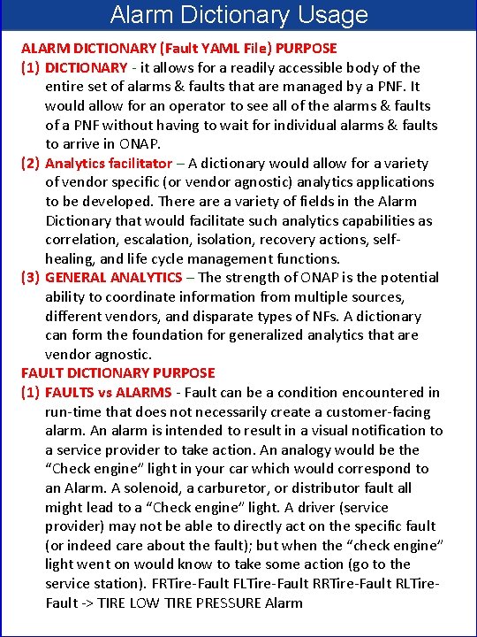
Alarm Dictionary Usage ALARM DICTIONARY (Fault YAML File) PURPOSE (1) DICTIONARY - it allows for a readily accessible body of the entire set of alarms & faults that are managed by a PNF. It would allow for an operator to see all of the alarms & faults of a PNF without having to wait for individual alarms & faults to arrive in ONAP. (2) Analytics facilitator – A dictionary would allow for a variety of vendor specific (or vendor agnostic) analytics applications to be developed. There a variety of fields in the Alarm Dictionary that would facilitate such analytics capabilities as correlation, escalation, isolation, recovery actions, selfhealing, and life cycle management functions. (3) GENERAL ANALYTICS – The strength of ONAP is the potential ability to coordinate information from multiple sources, different vendors, and disparate types of NFs. A dictionary can form the foundation for generalized analytics that are vendor agnostic. FAULT DICTIONARY PURPOSE (1) FAULTS vs ALARMS - Fault can be a condition encountered in run-time that does not necessarily create a customer-facing alarm. An alarm is intended to result in a visual notification to a service provider to take action. An analogy would be the “Check engine” light in your car which would correspond to an Alarm. A solenoid, a carburetor, or distributor fault all might lead to a “Check engine” light. A driver (service provider) may not be able to directly act on the specific fault (or indeed care about the fault); but when the “check engine” light went on would know to take some action (go to the service station). FRTire-Fault FLTire-Fault RRTire-Fault RLTire. Fault -> TIRE LOW TIRE PRESSURE Alarm
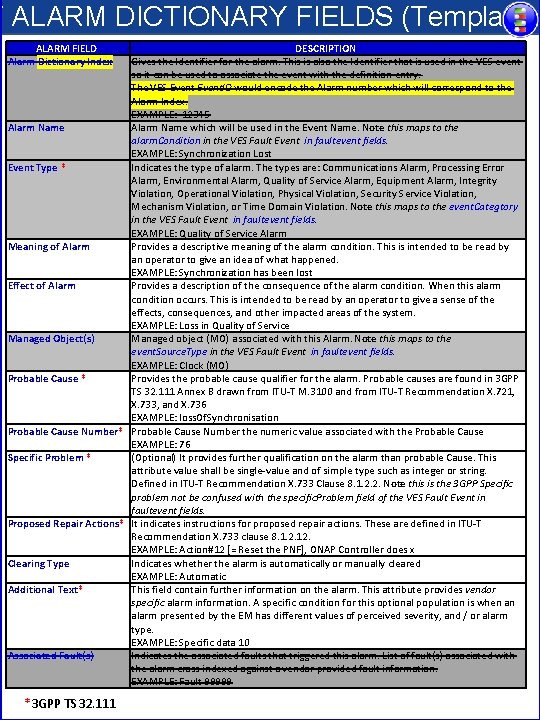
F ALARM DICTIONARY FIELDS (Template) ALARM FIELD Alarm Dictionary Index DESCRIPTION Gives the Identifier for the alarm. This is also the Identifier that is used in the VES event so it can be used to associate the event with the definition entry. The VES Event. ID would encode the Alarm number which will correspond to the Alarm Index. EXAMPLE: 12345 Alarm Name which will be used in the Event Name. Note this maps to the alarm. Condition in the VES Fault Event in faultevent fields. EXAMPLE: Synchronization Lost Event Type * Indicates the type of alarm. The types are: Communications Alarm, Processing Error Alarm, Environmental Alarm, Quality of Service Alarm, Equipment Alarm, Integrity Violation, Operational Violation, Physical Violation, Security Service Violation, Mechanism Violation, or Time Domain Violation. Note this maps to the event. Categtory in the VES Fault Event in faultevent fields. EXAMPLE: Quality of Service Alarm Meaning of Alarm Provides a descriptive meaning of the alarm condition. This is intended to be read by an operator to give an idea of what happened. EXAMPLE: Synchronization has been lost Effect of Alarm Provides a description of the consequence of the alarm condition. When this alarm condition occurs. This is intended to be read by an operator to give a sense of the effects, consequences, and other impacted areas of the system. EXAMPLE: Loss in Quality of Service Managed Object(s) Managed object (MO) associated with this Alarm. Note this maps to the event. Source. Type in the VES Fault Event in faultevent fields. EXAMPLE: Clock (MO) Probable Cause * Provides the probable cause qualifier for the alarm. Probable causes are found in 3 GPP TS 32. 111 Annex B drawn from ITU-T M. 3100 and from ITU-T Recommendation X. 721, X. 733, and X. 736 EXAMPLE: loss. Of. Synchronisation Probable Cause Number* Probable Cause Number the numeric value associated with the Probable Cause EXAMPLE: 76 Specific Problem * (Optional) It provides further qualification on the alarm than probable Cause. This attribute value shall be single-value and of simple type such as integer or string. Defined in ITU-T Recommendation X. 733 Clause 8. 1. 2. 2. Note this is the 3 GPP Specific problem not be confused with the specific. Problem field of the VES Fault Event in faultevent fields. Proposed Repair Actions* It indicates instructions for proposed repair actions. These are defined in ITU-T Recommendation X. 733 clause 8. 1. 2. 12. EXAMPLE: Action#12 [= Reset the PNF], ONAP Controller does x Clearing Type Indicates whether the alarm is automatically or manually cleared EXAMPLE: Automatic Additional Text* This field contain further information on the alarm. This attribute provides vendor specific alarm information. A specific condition for this optional population is when an alarm presented by the EM has different values of perceived severity, and / or alarm type. EXAMPLE: Specific data 10 Associated Fault(s) Indicates the associated faults that triggered this alarm. List of fault(s) associated with the alarm cross indexed against a vendor provided fault information. EXAMPLE: Fault 99999 *3 GPP TS 32. 111
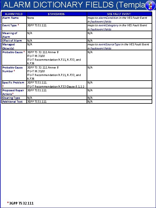
F ALARM DICTIONARY FIELDS (Template) ALARM FIELD Alarm Name None Event Type * 3 GPP TS 32. 111 Meaning of Alarm Effect of Alarm Managed Object(s) Probable Cause * N/A N/A STANDARDS VES FAULT EVENT maps to alarm. Condition in the VES Fault Event in faultevent fields maps to event. Categtory in the VES Fault Event in faultevent fields N/A maps to event. Source. Type in the VES Fault Event in faultevent fields N/A 3 GPP TS 32. 111 Annex B ITU-T M. 3100 ITU-T Recommendation X. 721, X. 733, and X. 736 Probable Cause 3 GPP TS 32. 111 Annex B N/A Number * ITU-T M. 3100 ITU-T Recommendation X. 721, X. 733, and X. 736 Specific Problem 3 GPP TS 32. 111. N/A * ITU-T Recommendation X. 733 Clause 8. 1. 2. 2 Proposed Repair 3 GPP TS 32. 111 N/A Actions* Clearing Type N/A Additional Text 3 GPP TS 32. 111 N/A *3 GPP TS 32. 111
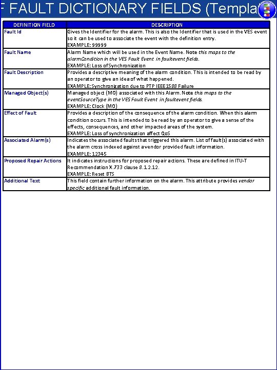
F FAULT DICTIONARY FIELDS (Template) DEFINITION FIELD Fault Id Fault Name Fault Description Managed Object(s) Effect of Fault Associated Alarm(s) Proposed Repair Actions Additional Text DESCRIPTION Gives the Identifier for the alarm. This is also the Identifier that is used in the VES event so it can be used to associate the event with the definition entry. EXAMPLE: 99999 Alarm Name which will be used in the Event Name. Note this maps to the alarm. Condition in the VES Fault Event in faultevent fields. EXAMPLE: Loss of Synchronization Provides a descriptive meaning of the alarm condition. This is intended to be read by an operator to give an idea of what happened. EXAMPLE: Synchronization due to PTP IEEE 1588 Failure Managed object (MO) associated with this Alarm. Note this maps to the event. Source. Type in the VES Fault Event in faultevent fields. EXAMPLE: Clock (MO) Provides a description of the consequence of the alarm condition. When this alarm condition occurs. This is intended to be read by an operator to give a sense of the effects, consequences, and other impacted areas of the system. EXAMPLE: Loss of synchronization affect Qo. S Indicates the associated faults that triggered this alarm. List of fault(s) associated with the alarm cross indexed against a vendor provided fault information. EXAMPLE: 12345 It indicates instructions for proposed repair actions. These are defined in ITU-T Recommendation X. 733 clause 8. 1. 2. 12. EXAMPLE: Reset BTS This field contain further information on the alarm. This attribute provides vendor specific additional fault information.
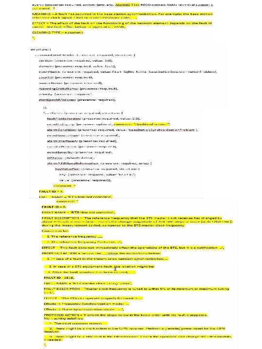
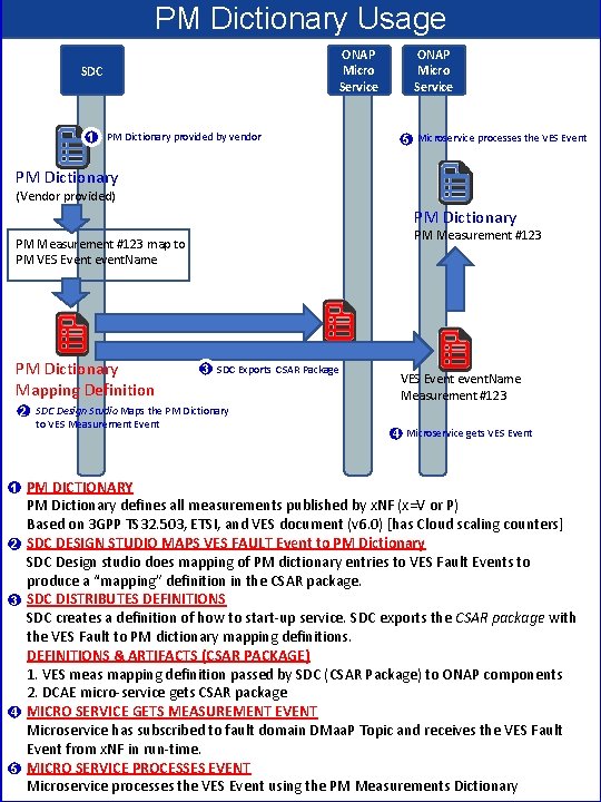
PM Dictionary Usage ONAP Micro Service SDC 1 PM Dictionary provided by vendor ONAP Micro Service 5 Microservice processes the VES Event PM Dictionary (Vendor provided) PM Dictionary PM Measurement #123 map to PM VES Event event. Name PM Dictionary Mapping Definition 3 SDC Exports CSAR Package VES Event event. Name Measurement #123 2 SDC Design Studio Maps the PM Dictionary to VES Measurement Event 1 2 3 4 5 4 Microservice gets VES Event PM DICTIONARY PM Dictionary defines all measurements published by x. NF (x=V or P) Based on 3 GPP TS 32. 503, ETSI, and VES document (v 6. 0) [has Cloud scaling counters] SDC DESIGN STUDIO MAPS VES FAULT Event to PM Dictionary SDC Design studio does mapping of PM dictionary entries to VES Fault Events to produce a “mapping” definition in the CSAR package. SDC DISTRIBUTES DEFINITIONS SDC creates a definition of how to start-up service. SDC exports the CSAR package with the VES Fault to PM dictionary mapping definitions. DEFINITIONS & ARTIFACTS (CSAR PACKAGE) 1. VES meas mapping definition passed by SDC (CSAR Package) to ONAP components 2. DCAE micro-service gets CSAR package MICRO SERVICE GETS MEASUREMENT EVENT Microservice has subscribed to fault domain DMaa. P Topic and receives the VES Fault Event from x. NF in run-time. MICRO SERVICE PROCESSES EVENT Microservice processes the VES Event using the PM Measurements Dictionary

PM Dictionary Usage
APPENDIX & Meeting Notes
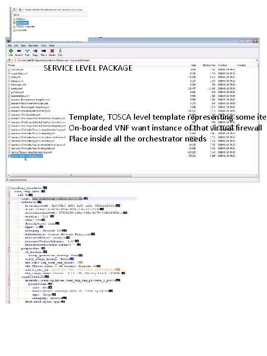
SERVICE LEVEL PACKAGE Template, TOSCA level template representing some item On-boarded VNF want instance of that virtual firewall Place inside all the orchestrator needs
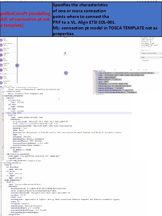
Specifies the characteristics of one or more connection pnf. Ext. Conn. Pt (modelling points where to connect the def. of connection pt not PNF to a VL. Align ETSI SOL-001. a template) ML: connection pt model in TOSCA TEMPLATE not as properties.
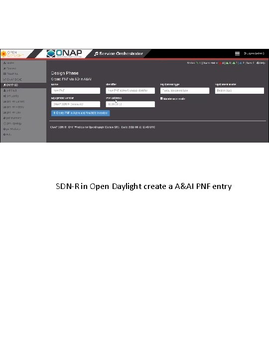
SDN-R in Open Daylight create a A&AI PNF entry
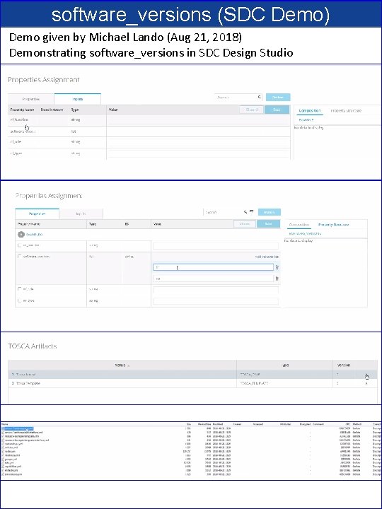
software_versions (SDC Demo) Demo given by Michael Lando (Aug 21, 2018) Demonstrating software_versions in SDC Design Studio
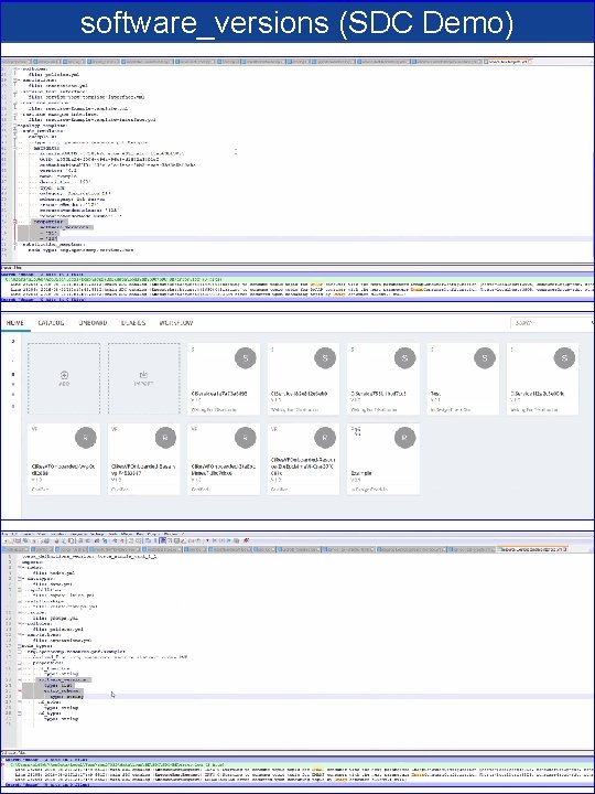
software_versions (SDC Demo)
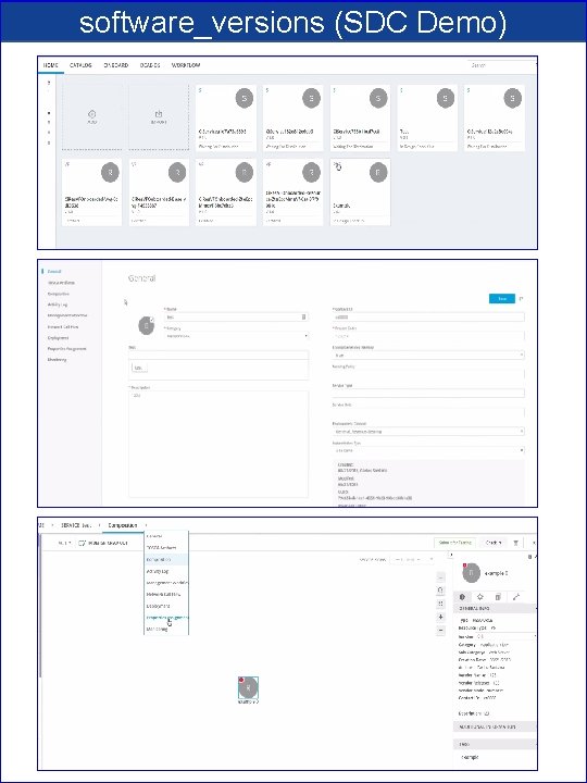
software_versions (SDC Demo)
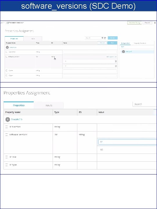
software_versions (SDC Demo)
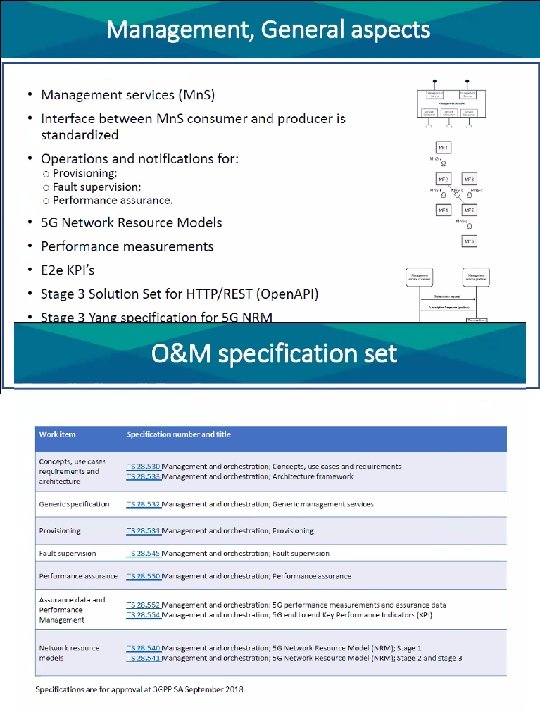
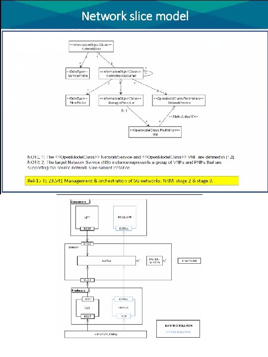
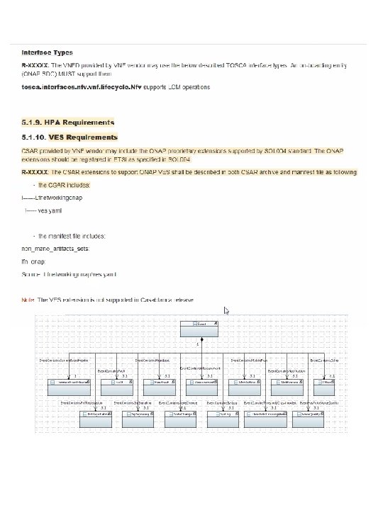

- Slides: 104