
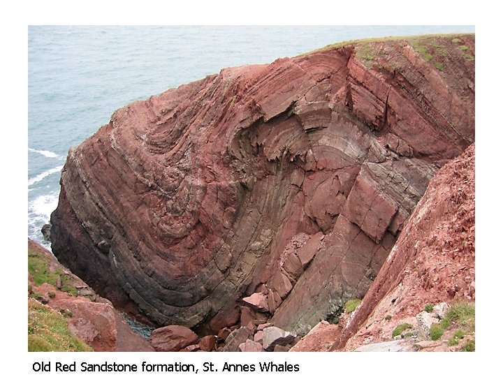
Old Red Sandstone formation St Annes Whales Were






- Slides: 38
Old Red Sandstone formation, St. Annes Whales
We’re looking at a Profile Plane cut through these folds Antiform Synform Axial Traces Old Red Sandstone formation, St. Annes Whales
Today’s Topics • Fold geometry and classification • Apparent thickness and apparent dip
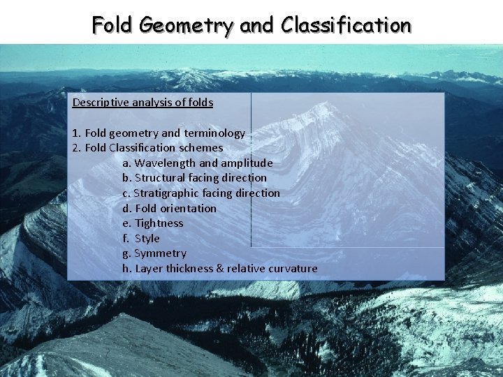
Fold Geometry and Classification Descriptive analysis of folds 1. Fold geometry and terminology 2. Fold Classification schemes a. Wavelength and amplitude b. Structural facing direction c. Stratigraphic facing direction d. Fold orientation e. Tightness f. Style g. Symmetry h. Layer thickness & relative curvature
Fold profile plane
Fold Terminology Additional terms: Note: For cylindrical folds, the fold axis and hinge line are parallel, but the hinge line has a fixed material location on the folded surface.
Fold Terminology How do we uniquely define the geometry of a fold? Most folds don’t have truly “planar” axial planes; hence, axial surface. MOst Axial trace on the profile plane Another term: axial trace…a linear feature
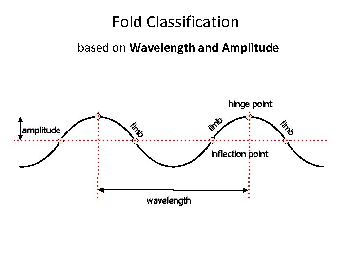
Fold Classification based on Wavelength and Amplitude hinge point inflection point wavelength b lim amplitude b il m
Fold Classification based on Structural facing direction Antiform – close upward, hinge at top Synform – close downward, hinge at bottom
Fold Classification based on Stratigraphic facing direction Anticline Syncline Eocene Cretaceous n ria b m Ca Oldest rocks in the center of the fold Ju ras sic Youngest rocks in the center of the fold
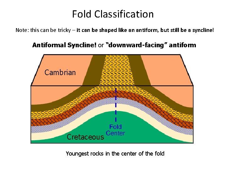
Fold Classification Note: this can be tricky – it can be shaped like an antiform, but still be a syncline! Antiformal Syncline! or “downward-facing” antiform Cambrian Cretaceous Youngest rocks in the center of the fold
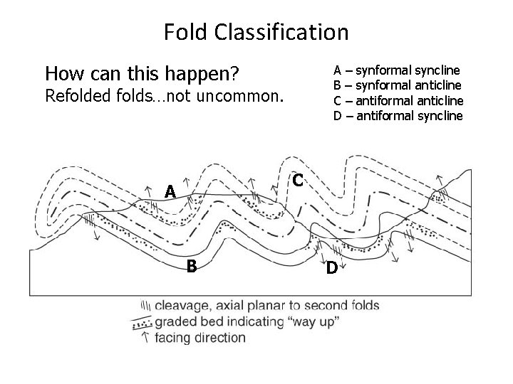
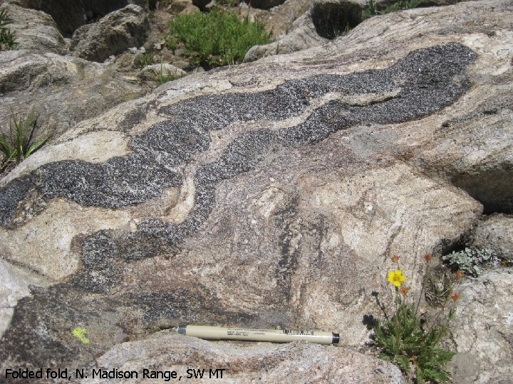
Fold Classification How can this happen? A – synformal syncline B – synformal anticline C – antiformal anticline D – antiformal syncline Refolded folds…not uncommon. C A B D
Folded fold, N. Madison Range, SW MT
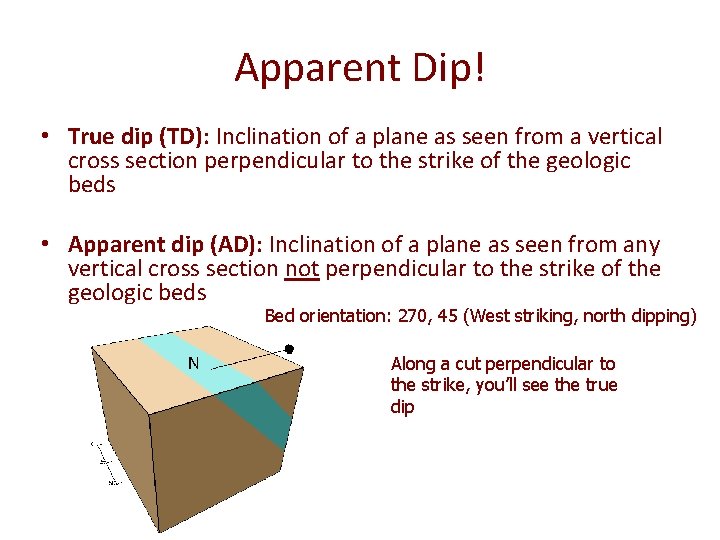
Apparent Dip! • True dip (TD): Inclination of a plane as seen from a vertical cross section perpendicular to the strike of the geologic beds • Apparent dip (AD): Inclination of a plane as seen from any vertical cross section not perpendicular to the strike of the geologic beds Bed orientation: 270, 45 (West striking, north dipping) Along a cut perpendicular to the strike, you’ll see the true dip
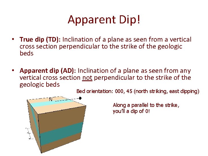
Apparent Dip! • True dip (TD): Inclination of a plane as seen from a vertical cross section perpendicular to the strike of the geologic beds • Apparent dip (AD): Inclination of a plane as seen from any vertical cross section not perpendicular to the strike of the geologic beds Bed orientation: 000, 45 (north striking, east dipping) Along a parallel to the strike, you’ll a dip of 0!
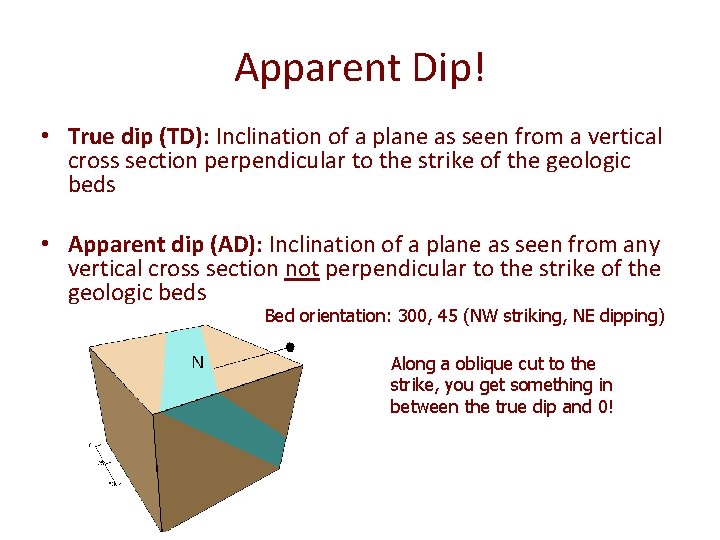
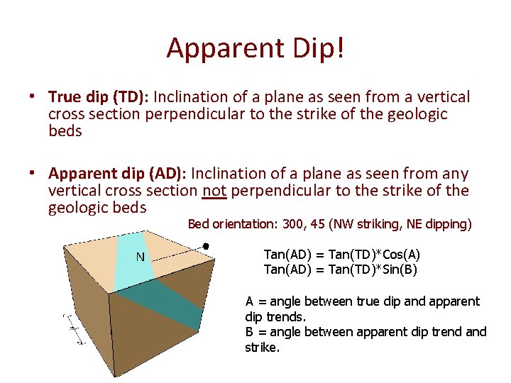
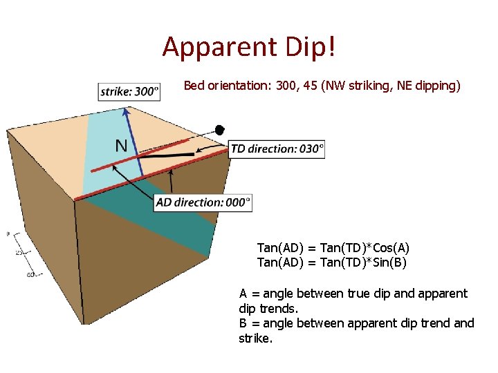
Apparent Dip! • True dip (TD): Inclination of a plane as seen from a vertical cross section perpendicular to the strike of the geologic beds • Apparent dip (AD): Inclination of a plane as seen from any vertical cross section not perpendicular to the strike of the geologic beds Bed orientation: 300, 45 (NW striking, NE dipping) Along a oblique cut to the strike, you get something in between the true dip and 0!
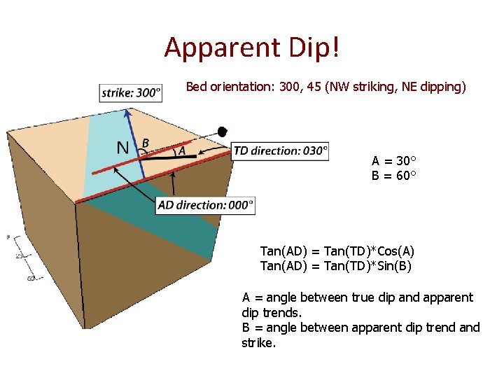
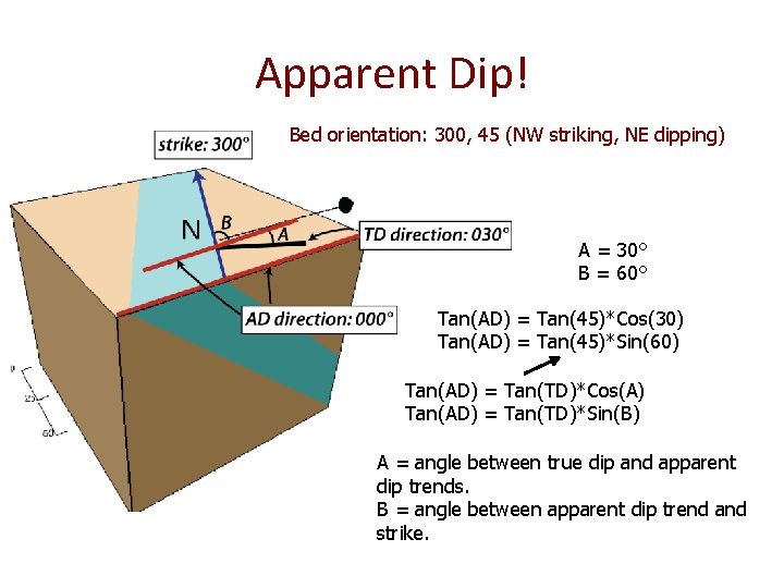
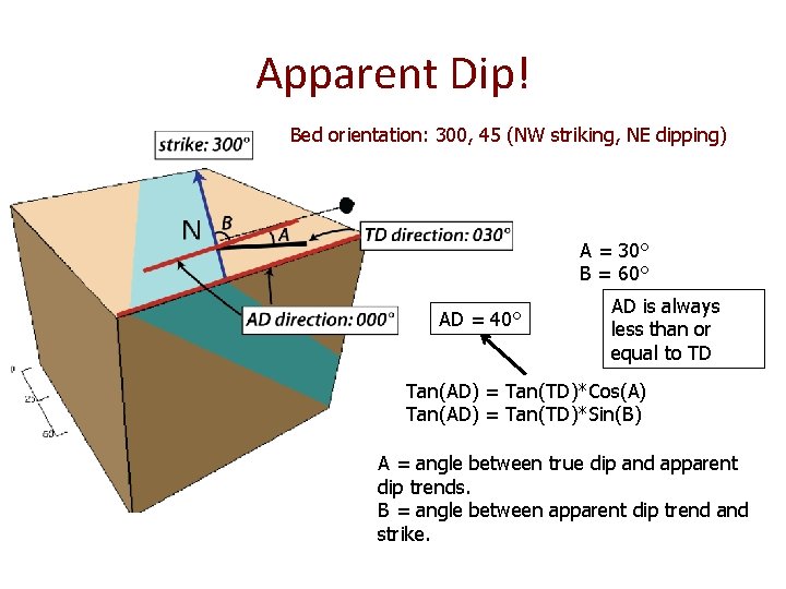
Apparent Dip! • True dip (TD): Inclination of a plane as seen from a vertical cross section perpendicular to the strike of the geologic beds • Apparent dip (AD): Inclination of a plane as seen from any vertical cross section not perpendicular to the strike of the geologic beds Bed orientation: 300, 45 (NW striking, NE dipping) Tan(AD) = Tan(TD)*Cos(A) Tan(AD) = Tan(TD)*Sin(B) A = angle between true dip and apparent dip trends. B = angle between apparent dip trend and strike.
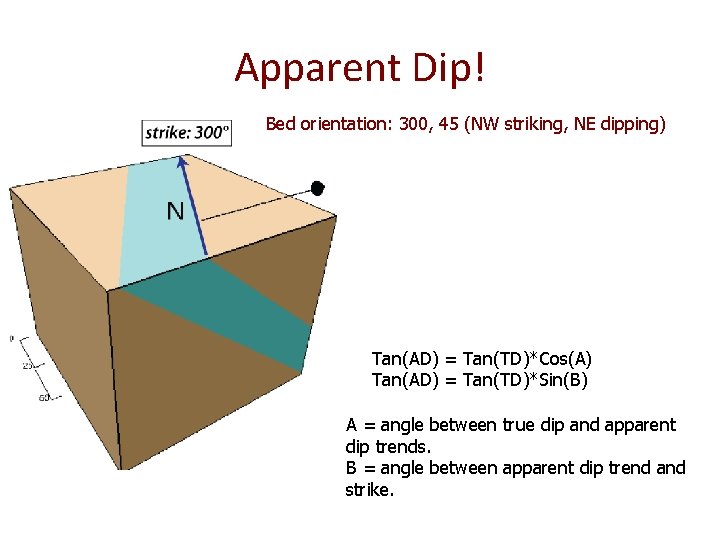
Apparent Dip! Bed orientation: 300, 45 (NW striking, NE dipping) Tan(AD) = Tan(TD)*Cos(A) Tan(AD) = Tan(TD)*Sin(B) A = angle between true dip and apparent dip trends. B = angle between apparent dip trend and strike.
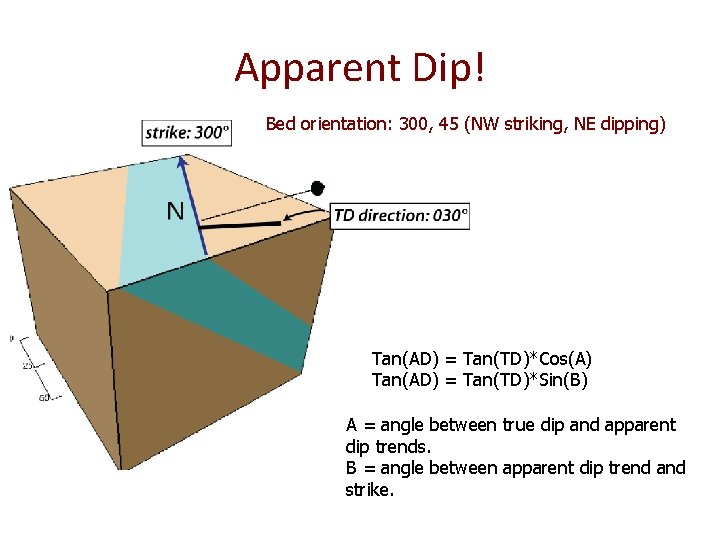
Apparent Dip! Bed orientation: 300, 45 (NW striking, NE dipping) Tan(AD) = Tan(TD)*Cos(A) Tan(AD) = Tan(TD)*Sin(B) A = angle between true dip and apparent dip trends. B = angle between apparent dip trend and strike.
Apparent Dip! Bed orientation: 300, 45 (NW striking, NE dipping) Tan(AD) = Tan(TD)*Cos(A) Tan(AD) = Tan(TD)*Sin(B) A = angle between true dip and apparent dip trends. B = angle between apparent dip trend and strike.
Apparent Dip! Bed orientation: 300, 45 (NW striking, NE dipping) A = 30° B = 60° Tan(AD) = Tan(TD)*Cos(A) Tan(AD) = Tan(TD)*Sin(B) A = angle between true dip and apparent dip trends. B = angle between apparent dip trend and strike.
Apparent Dip! Bed orientation: 300, 45 (NW striking, NE dipping) A = 30° B = 60° Tan(AD) = Tan(45)*Cos(30) Tan(AD) = Tan(45)*Sin(60) Tan(AD) = Tan(TD)*Cos(A) Tan(AD) = Tan(TD)*Sin(B) A = angle between true dip and apparent dip trends. B = angle between apparent dip trend and strike.
Apparent Dip! Bed orientation: 300, 45 (NW striking, NE dipping) A = 30° B = 60° AD = 40° AD is always less than or equal to TD Tan(AD) = Tan(TD)*Cos(A) Tan(AD) = Tan(TD)*Sin(B) A = angle between true dip and apparent dip trends. B = angle between apparent dip trend and strike.
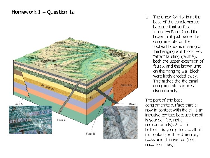
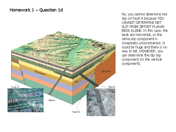
Homework 1 – Question 1 a 1. The unconformity is at the base of the conglomerate because that surface truncates Fault A and the brown unit just below the conglomerate on the footwall block is missing on the hanging wall block. So, “after” faulting (fault A), both the upper extension of fault A and the brown unit on the hanging wall block were likely eroded away. This makes the basal conglomerate surface a disconformity. The part of this basal conglomerate surface that is now in contact with the sill is an intrusive contact because the sill is younger (so, not a nonconformity). And the batholith is young too, so all of it’s contacts with sedimentary rocks are intrusive too (not unconformities).
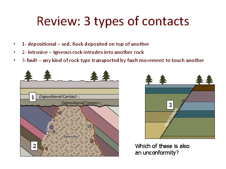
Review: 3 types of contacts • • • 1 - depositional – sed. Rock deposited on top of another 2 - intrusive – Igneous rock intrudes into another rock 3 -fault – any kind of rock type transported by fault movement to touch another 1 3 2 Which of these is also an unconformity?
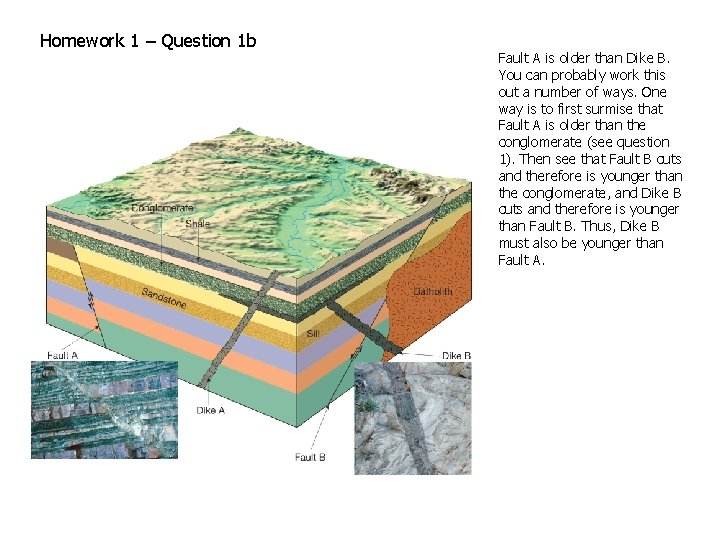
Homework 1 – Question 1 b Fault A is older than Dike B. You can probably work this out a number of ways. One way is to first surmise that Fault A is older than the conglomerate (see question 1). Then see that Fault B cuts and therefore is younger than the conglomerate, and Dike B cuts and therefore is younger than Fault B. Thus, Dike B must also be younger than Fault A.
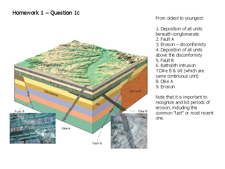
Homework 1 – Question 1 c From oldest to youngest: 1. Deposition of all units beneath conglomerate. 2. Fault A 3. Erosion – disconformity 4. Deposition of all units above the disconformity 5. Fault B 6. Batholith intrusion 7. Dike B & sill (which are same continuous unit) 8. Dike A 9. Erosion Note that it is important to recognize and list periods of erosion, including the common “last” or most recent one.
Homework 1 – Question 1 d No, you cannot determine net slip on Fault A because YOU CANNOT DETERMINE NET SLIP FROM OFFSET PLANAR BEDS ALONE. In this case, the beds are horizontal, so the strike-slip component is completely unconstrained. It could be huge and there is no way to tell. HOWEVER, you can determine the dip slip component (or the vertical component).
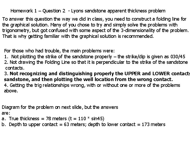
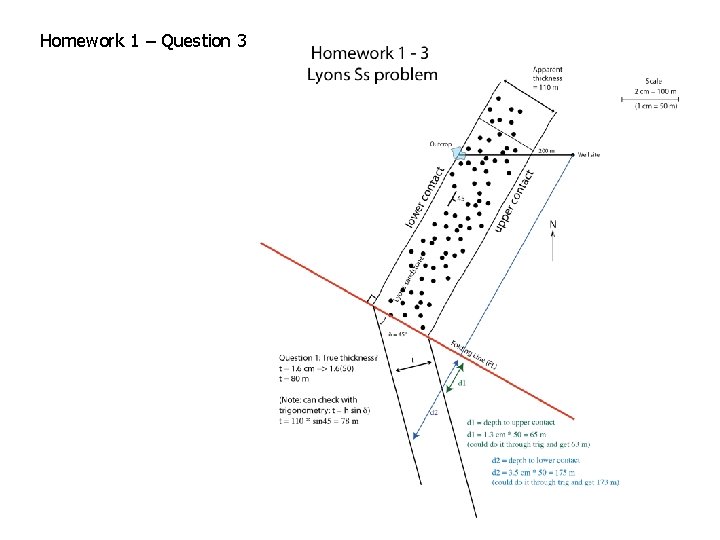
Homework 1 – Question 2 - Lyons sandstone apparent thickness problem To answer this question the way we did in class, you need to construct a folding line for the graphical solution. Many of you chose to try and simply solve the problems with trigonometry, but got confused with some aspect of the 3 -dimensionality of the problem. That is why getting familiar with the graphical solution is recommended. For those who had trouble, the main problems were: 1. Not plotting the strike of the sandstone properly – the strike/dip is given as 030/45 2. Not drawing the Folding Line so that it is perpendicular to the strike of the sandstone contacts. 3. Not recognizing and distinguishing properly the UPPER and LOWER contacts sandstone, and then plotting the well location from the wrong contact. 4. Getting the trig relationships wrong, with or without one or more of the problems above. Diagram for the problem on next slide, but the answers are: a. True thickness = 78 meters (t = 110 * sin 45) b. Depth to upper contact = 63 meters; depth to lower contact = 173 meters
Homework 1 – Question 3
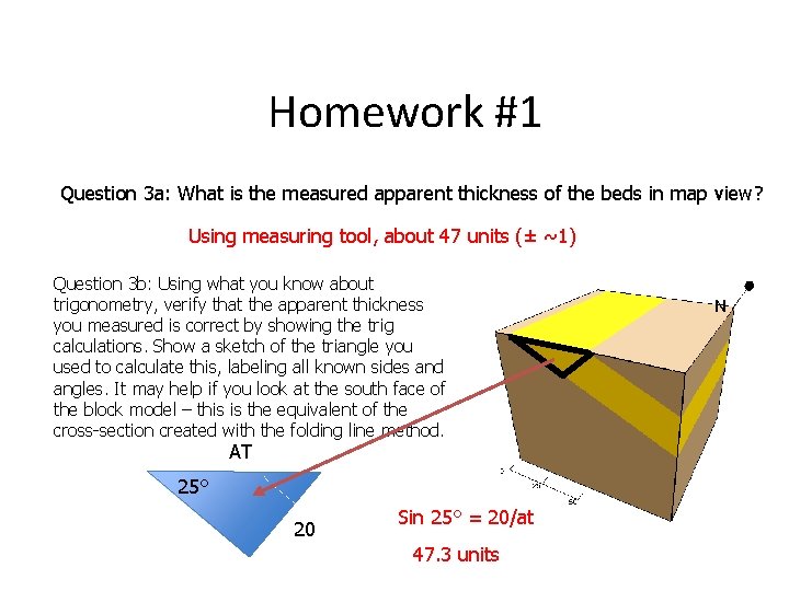
Homework #1 Question 3 a: What is the measured apparent thickness of the beds in map view? Using measuring tool, about 47 units (± ~1) Question 3 b: Using what you know about trigonometry, verify that the apparent thickness you measured is correct by showing the trig calculations. Show a sketch of the triangle you used to calculate this, labeling all known sides and angles. It may help if you look at the south face of the block model – this is the equivalent of the cross-section created with the folding line method. AT 25° 20 Sin 25° = 20/at 47. 3 units
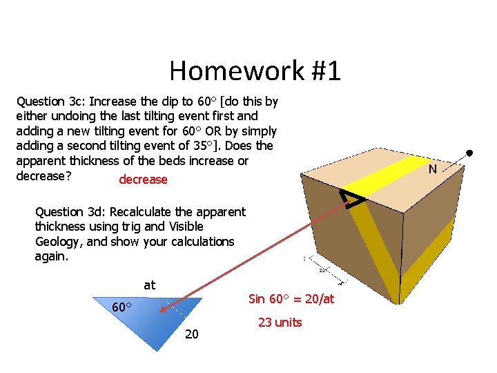
Homework #1 Question 3 c: Increase the dip to 60° [do this by either undoing the last tilting event first and adding a new tilting event for 60° OR by simply adding a second tilting event of 35°]. Does the apparent thickness of the beds increase or decrease? decrease Question 3 d: Recalculate the apparent thickness using trig and Visible Geology, and show your calculations again. at Sin 60° = 20/at 60° 20 23 units
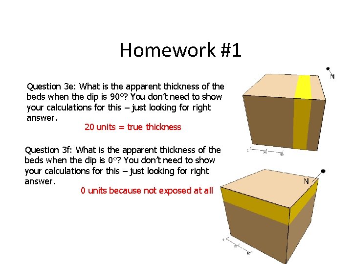
Homework #1 Question 3 e: What is the apparent thickness of the beds when the dip is 90°? You don’t need to show your calculations for this – just looking for right answer. 20 units = true thickness Question 3 f: What is the apparent thickness of the beds when the dip is 0°? You don’t need to show your calculations for this – just looking for right answer. 0 units because not exposed at all
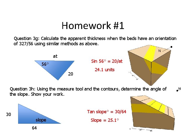
Homework #1 Question 3 g: Calculate the apparent thickness when the beds have an orientation of 327/56 using similar methods as above. at Sin 56° = 20/at 56° 20 24. 1 units Question 3 h: Using the measure tool and the contours, determine the angle of the slope. Show your work. Tan slope° = 30/64 30 slope 64 Slope = 25. 1°
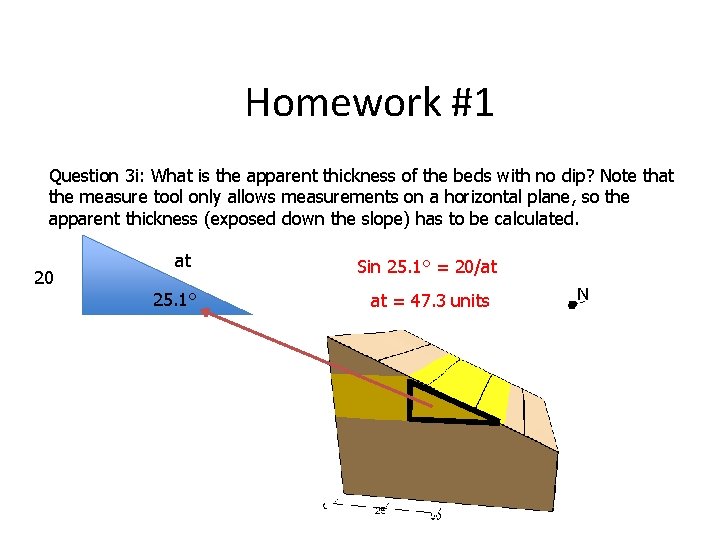
Homework #1 Question 3 i: What is the apparent thickness of the beds with no dip? Note that the measure tool only allows measurements on a horizontal plane, so the apparent thickness (exposed down the slope) has to be calculated. 20 at 25. 1° Sin 25. 1° = 20/at at = 47. 3 units
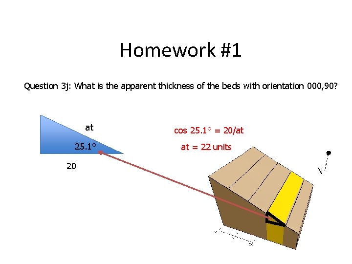
Homework #1 Question 3 j: What is the apparent thickness of the beds with orientation 000, 90? at 25. 1° 20 cos 25. 1° = 20/at at = 22 units
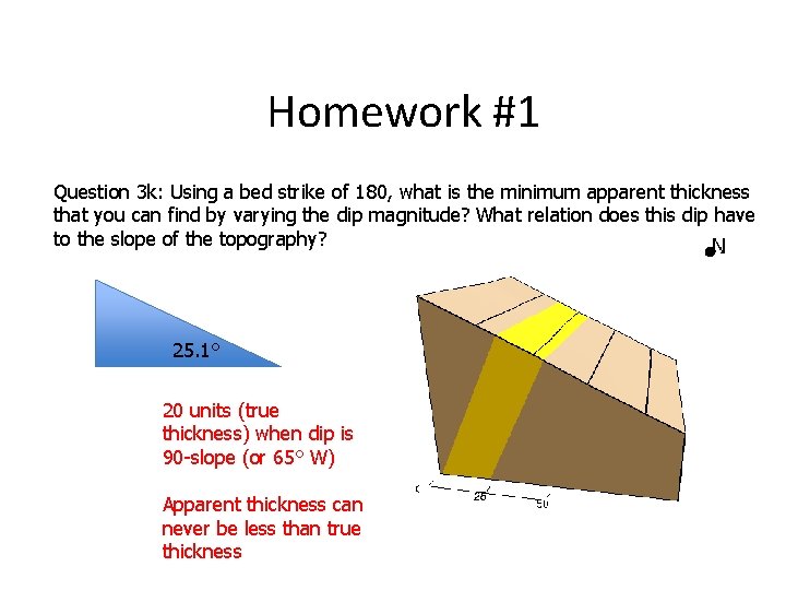
Homework #1 Question 3 k: Using a bed strike of 180, what is the minimum apparent thickness that you can find by varying the dip magnitude? What relation does this dip have to the slope of the topography? 25. 1° 20 units (true thickness) when dip is 90 -slope (or 65° W) Apparent thickness can never be less than true thickness
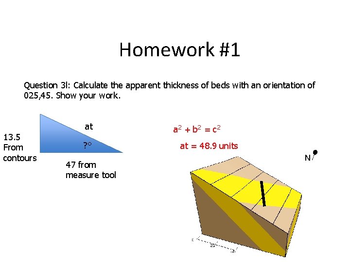
Homework #1 Question 3 l: Calculate the apparent thickness of beds with an orientation of 025, 45. Show your work. at 13. 5 From contours ? ° 47 from measure tool a 2 + b 2 = c 2 at = 48. 9 units