Ohms Law Determining Watts Amperes and Power Factors


 I E CURRENT (AMPS) VOLTAGE (VOLTS) UNITS")


 V A VOLTS AMPS (CURRENT) (VOLTAGE) Watts = 1, 300 Volts")


 I E CURRENT (AMPS) VOLTAGE")

 = 1, 300 Volts =")


- Slides: 47
Ohm’s Law Determining Watts, Amperes and Power Factors using Ohm’s Law S. Bell Georgia Agricultural Education
The first step in developing an understanding of Ohm’s Law and how to use it for making electrical calculations is to develop a basic understanding of electrical terms and symbols used in Ohm’s Law.
Voltage – the difference in electrical potential energy between two points per unit electric charge. Simply, it is a pressure that pushes charged electrons through an electrical circuit. Almost all voltage in residential construction in the United States will be 120/240 volts. Often represented by the letter E for electromotive force. Voltage is “Nominal”; it may be more or less than 120 V depending upon a variety of factors but mainly ambient temperature and length or distance to the outlet or access point from the source.
Amperage – This is the strength of an electrical current, often referred as an amp. Over current devices such as breakers or fuses and wire sizing are all based on the amperage of a circuit. 100 to 200 -amp main electrical service panels are common sizes in residential construction and 15 or 20 -amp branch circuits are common for lighting and plug loads. Current is represented by the letter I for Intensity. 1 Amp = 6. 28 Quintillion electrons passing a given point/second
Resistance – a measure of the difficulty to pass an electrical current through a conductor. The concept is similar to friction and is measured in ohms. Resistance isn’t a very common measurement use when determining energy use but is used when sizing electrical conductors or service equipment. These are calculations that we do not usually do, but it does help one to understand why larger conductors are better capable of handling larger loads and carrying current longer distances. Resistance is represented by the letter R.
Wattage – Wattage is defined as the rate of doing work and is represented by the letter P. Wattage is the measurement of how electricity is billed and is the most useful electrical information to an energy auditor. Electricity is billed at a kilowatt hour, or 1000 watts used in an hour. Also referred to as Volt-Amps –VA (Assuming the Power Factor is 1) NEC requires a minimum of 180 VA/receptacle
Ohm’s law states that the current through a conductor between two points is directly proportional to the voltage across the two points. Where I is the current through the conductors in units of amperes, E is the voltage measured across the conductors in units of volts, and R is the resistance of the conductors in units of ohms. P symbolizes power, measured in watts. The formulas below represent the equations that are Ohm’s law: E/I=R E/R=I Ix. R=E P/I=E P/E=I Ix. E=P
Ohm’s Law BIG PICTURE P POWER (WATTS) I E CURRENT (AMPS) VOLTAGE (VOLTS) UNITS OF MEASURE W WATTS (POWER) A V AMPS VOLTS (CURRENT) (VOLTAGE )
Nominal Voltage Grounded or “Neutral” conductor side Ungrounded or “Hot” conductor side
Single Phase, 240 V Nominal 120 V phase “A” 120 V phase “B” 240
All electrical devices and appliances are required to have electrical information printed somewhere on the product. The photo below shows one of these tags.
This appliance nameplate happens to be a toaster oven. The tag states the oven operates at 120 volts at 60 Hertz (Hertz is the frequency of power, or how many times per second alternating power completes one cycle, all power in the United States operates at 60 Hertz). The power consumption of the toaster oven is 1, 300 watts. Knowing the appliance operates at 120 volts and uses 1, 300 watts, we can use ohms law to calculate how many amps it draws, useful for determining correct circuit breaker and wire sizing, or the resistance of the product.
W WATTS (POWER) V A VOLTS AMPS (CURRENT) (VOLTAGE) Watts = 1, 300 Volts = 120 Amperes = ? W = V x A 1, 300 W = 120 V x A 120 V 1, 300 ÷ 120 V = 10. 83 Amperes
What happens to the load on the toaster oven circuit if, due to voltage drop, I have only 110 volts at my receptacle? Watts = 1, 300 Volts = 110 Amperes = ? W = V x A 1, 300 W = 110 V x A 110 V 1, 300 ÷ 110 V = 11. 81 Amperes
Let’s calculate the load in Amperes for a coffee maker. Watts = 2, 200 Volts = 110 (Rated) Amperes = ? W = V x A 2, 200 W = 110 V x A 110 V 2, 200 ÷ 110 V = 20 Amperes
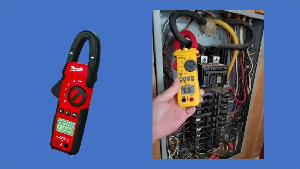
Great! Let’s make breakfast using our toaster oven and coffee maker! Lets say we have used our multimeter to measure the voltage on our kitchen circuit and we have 117 V
Toaster Oven Watts = 1, 300 Volts = 117 Amperes = ? Coffee Maker Watts = 2, 200 Volts = 117 Amperes = ? W = V x A 2, 200 W = 117 V x A 1, 300 W = 117 V x A 117 V 117 V 1, 300 ÷ 117 V = 11. 11 Amperes 2, 200 ÷ 117 V = 18. 8 Amperes
What is the total Load on our circuit? 11. 11 amp toaster + 18. 8 amp coffee maker = 29. 9 amps! Too much for a single 20 amp small appliance circuit! This is why the National Electrical Code requires that all kitchens be served by a minimum of 2 – small appliance circuits! NEC 210. 11(C)
Let’s determine the Ohm’s of resistance. P POWER (WATTS) I E CURRENT (AMPS) VOLTAGE (VOLTS) From our toaster oven nameplate P = Watts = 1, 300 W I = Intensity of Current = Amperes or Amps = ? E = Electromotive force = Volts = 120 V
From our name plate we know…. . Watts = 1, 300 Volts = 120 Resistance = ? V 2 R = Therefore, P Looks like we have some work to do!
From our name plate we know…. . Watts (P) = 1, 300 Volts = 120 V 2 R = P R = 1202 ÷ 1, 300 Watts R = 14, 400 ÷ 1, 300 Watts = 11. 076923 Ohm’s
What’s That Mean?
Resistance rating Higher numbers indicate a higher resistance rating, which means more energy will be required to integrate the component in a circuit. Pretty typical for any type of appliance with a heating element like a toaster oven, range, coffee maker etc. Also means an insulator would need to be capable of providing that amount of resistance to protect from electrical shock.
Test resistance in a circuit when it is unpowered. In other words, don't connect the circuit to a power supply when using your ohmmeter. Doing so could damage your digital ohmmeter or invalidate your resistance reading. The lower the number, the lower the resistance and the better the conductor. Ground rod readings should be very low if not “ 0”
Get a digital multimeter and set it to measure resistance in Ohm’s, . Place one of the leads on each end of a length of copper conductor to measure resistance. Try different lengths and different AWG sizes of conductors and discuss the difference and what it means. Ʊ
Review What does the letter P represent? P = Watts or Power = Work W What does the letter I represent? I = Amperage or Intensity of Current A What does the letter E represent? E = Volts or Electromotive Force = Pressure V
Let’s calculate the load for a bathroom circuit based on two hair dryer’s operating at the same time. What is the load in amperes for one, 120 V hair dryer rated at 1, 900 watts? W = V x A 1, 900 Watts = 120 V x A 120 V A = 15. 8
Can 2 hair dryers be used at the same time on a 20 amp bathroom circuit in Homemakers Cabin at the State FFA/FCCLA Center? NO !!!
Here’s a problem for all of the livestock show people out there. Get the nameplate rating of a livestock blower/dryer, and a set large animal clippers. Get the information from the name plate and determine the load in amperes for each device separately. If both of the devices are in use on the same circuit at the same time, what is the total load on the circuit?
Blower = 2040 Watts @ 120 V Large animal clippers = 240 Watts @ 120 V W = V x A Blower - 2040 Watts = 120 V x A 120 V Livestock Blower Load in Amperes = 17
Large Animal Livestock Clippers = 240 Watts @ 120 V W = V x A Clippers - 240 Watts = 120 V x A 120 V Clippers Load in Amperes = 2
What is the total load on the circuit if both devices are used simultaneously at the same receptacle? Livestock Blower Load in Amperes = 17 Clippers Load in Amperes = 2 Total Load in Amperes = 19 Will a 20 amp, circuit handle the total load of the livestock blower and the clippers at the same time?
For how long? ? ? ? What is your experience with running blowers and clippers at the same time? What do you think is happening in the circuit to cause breakers to trip if the blower and clippers used matched the load rating in this problem?
Greenhouse Fan Disconnect Three Phase Formulas Watts ____________ Amperes = 1. 732 x Volts x Power Factor Watts = 1. 732 x Volts x Amperes x Power Factor Volt-Amperes = 1. 732 x Volts x Amperes
Alrighty, this one is a doozey so hang on! What do we know from the nameplate rating of the disconnect and what exactly do we want to learn? Amps = ? (30 is disconnect rating) Volts = 240 3 Phase (Three Phase Conductors) H. P. (Horse Power) = 3 up to 7. 5 Watts = ? ? ? Power Factor = ? ? ? So, it looks like we have 3 unknown factors, Fan motor Amps (max and min), Watts and Power Factor…….
Since we know that this is a disconnect for a fan motor in the greenhouse, what we want to know is the amperage rating of the fan motor so we can size the conductor. This is an easy problem to solve, all we need is a copy of the National Electrical Code and the ability to use it! For our discussion, I’m going to tell you where to look in the code book. We need to look at Table 430. 250, Full Load Current for Three-Phase Alternating Current Motors.
From our table, we can determine that the rated amperage for a 3 H. P, 240 V, 3 -Phase motor is 9. 6 amperes. For a 7. 5 H. P. motor, the rating is 22 amperes.
So, how do we determine the number of Watts? We need to understand Horsepower. Theoretical horsepower for an electric motor is 746 watts/H. P. Actual horsepower for motors ½ H. P. or larger is 1, 000 Watts, and 1, 200 Watts for motors ½ H. P. or less. The standard H. P. rating for our disconnect is 3 so … 3 H. P. x 1, 000 Watts/H. P. = 3, 000 Watts
Using all of the information we have……. Watts = 1. 732 x Volts x Amperes x Power Factor 3, 000 watts = 1. 732 x 240 V x 9. 6 Amps x Power Factor 3, 000 watts = 3, 990. 528 VA x Power Factor 3, 000 watts = 3, 990. 528 VA x Power Factor 3, 990. 528 k. VA 3, 990. 528 VA Power Factor = 0. 75 or 75% Power Factor
Which means…. When we use the amperage of the motor to determine the conductor size for the circuit, we must increase the ampacity by 133% which we can do by multiplying our amperage by 1. 33 to allow for the inefficiency of the motor. (100 ÷. 75 power factor = 133% ÷ 100 = 1. 33)
So, 9. 6 Amps x 1. 33 = 12. 769 amps This represents the full load rated amperage for a 3 H. P. , 9. 6 amp, 240 v, 3 -phase motor with a Power Factor of 75%
For a 7. 5 H. P. motor… 7. 5 x 1, 000 watts/H. P. = 7, 500 Watts 7, 500 watts = 1. 732 x 240 V x 22 Amps x Power Factor 7, 500 watts = 9, 144. 96 VA x Power Factor 7, 500 watts = 9, 144. 96 VA x Power Factor 9, 144. 96 VA Power Factor = 0. 82 or 82% Power Factor
Which means…. When we use the amperage of the motor to determine the conductor size for the circuit, we must increase the ampacity by 122% which we can do by multiplying our amperage by 1. 22 to allow for the inefficiency of the motor. (100 ÷. 82 power factor = 122% ÷ 100 = 1. 22)
So, 22 Amps x 1. 22 = 26. 84 amps This represents the full load rated amperage for a 7. 5 H. P. , 22 amp, 240 v, 3 -phase motor with a Power Factor of 82%, which is why our disconnect is rated at 30 amps!
Student Activity Compare the amperage of the compact fluorescent bulb to the current rating of the halogen bulb fixture. What does the information tell you about the differences between the two?
Compact fluorescent 9 Watts = 120 V x Amps 120 V 9 Watts ÷ 120 V =. 075 Amps Halogen Fixture = 8. 33 Amps and 1, 000 Watts! What’s that mean as it relates to resistance, heat emitted by the lights and cost of operation?