Ocean thermal energy conversion system OTEC Converted to

 stored in the ocean Electricity OTEC 2 nd law")


 Evaporate at Low")
 TB (cold sink)")
 200 k. W H-OTEC in Goseong")


 Generator")

 process so constant enthalpy (Total kinetic &")


- Slides: 26
Ocean thermal energy conversion system - OTEC
Converted to Solar energy (heat) stored in the ocean Electricity OTEC 2 nd law of thermodynamics Use of ocean Temperature gradients Warm surface & cold deep temperature difference 20 o. C
Availability of OTEC 80% solar radiation incident on earth Annual energy flux of 0. 85 x 1018 k. Wh Near Equator at surface ocean/sq m 17 – 20 MJ/m 2 Surface temperature varies Season & Latitude Equatorial zone temperature range 27 -30 o. C depending on season
Variation of ocean surface water temperature with latitude & season
Theory and working Principle of OTEC Ocean Temperature difference between surface and bottom More radiation in surface water & become lighter No thermal Convection 대류 between hot & cold water Surface thermal water is source 20 o. C Heat engine operated by temperature difference Bottom cold water is sink
Reversible heat engine connect between source & sink Absorption of solar radiation varies in water expressed by Lambert’s Law d. IY / d. Y = µI (or) IY = I e-µy IY = Radiation intensity at depth Y from water surface & falls exponentially (highly) with depth I = Radiation intensity at water surface µ = Extinction or absorption coefficient
OTC suitable for islands around tropical region East Pacific Ocean Because these areas provide both energy and distillate pure water at the same time with low cost Ocean temperature different (surface & bottom) 24 o. C
Carnot efficiency It is theoretical maximum efficiency can get when the heat engine is operating between two temperatures Reverse heat engine: Device that transfers energy from lower temperature to a higher temperature by doing work on the system. Efficiency of OTEC plant = carnot X relative efficiency Reverse heat engine operate at surface Ts (hot source) & deep TB water (cold sink) carnot = Ts-TB / Ts
Efficiency of real engine energy is less than Ideal energy getting from Carnot cycle Real engine Energy value < theoretical value from getting Carnot cycle Operate based on Rankine cycle Physical layout of the four main devices used in the Rankine cycle. 1. Pump 2. Boiler 3. Turbine 4. Condenser
Warm not sufficient for power generation Need secondary fluid (Ammonia, propane) Evaporate at Low Temperature Condensed in condenser after expand in turbine AC current Ammonia Boiling point: -33. 34 °C Propane Boiling point: -42 °C Ts TB
Ts (hot source) TB (cold sink)
Korea Institute of Ocean Science & Technology (KIOST) 200 k. W H-OTEC in Goseong Successfully finished 200 k. W OTEC pilot plant 200 k. W H-OTEC in Goseong
Location of OTEC system Floating Plant Land-Based Plant 10 – 15 Km from shore Self-Mounted Plant Platform anchored to seafloor DC power transfer using underground cable Plant (Ship) mooring located distance from the shore is no longer problem in offshore oil & gas production Depends on cold & warm water supply Grazing Plant Advantage: Cold water pipe vertically reach bottom Disadvantage: Power generated take to shore & positioning the ship at water depths of 2 km Similarly expect no problem for OTEC also Mooring
Location of OTEC system Floating Plant Land-Based Plant Depends on cold & warm water supply Self-Mounted Plant Grazing Plant
Location of OTEC system Floating Plant Build on land Land-Based Plant Depends on cold & warm water supply Self-Mounted Plant No power transmission cable required Required 800 – 1000 meters length of cold water pipe reach up to seabed Greater warming of cold water before it reach Grazing Plant Mooring (anchor) cost not required Plant at coast where deep water available within 2 -3 km from shore
Location of OTEC system Floating Plant Land-Based Plant Depends on cold & warm water supply Self-Mounted Plant Grazing Plant
Location of OTEC system Floating Plant Land-Based Plant Depends on cold & warm water supply Self-Mounted Plant Grazing Plant Used in shallow depth places Plant mounted on platform after the shallow sea Generated power taken by underground cable to tower - depth 50 – 100 m
Location of OTEC system Floating Plant Land-Based Plant OTEC fixed in ships Product carried by shuttle tankers to energy needed countries Depends on cold & warm water supply Self-Mounted Plant Grazing Plant Free to move anywhere having high temperature difference in sea Being utilized to split into liquid hydrogen & liquid oxygen More economical
Types of OTEC system Open or Claude Cycle Similar to closed cycle Surface warm seawater turn into 12 m /MW Large diameter turbine used Closed or Anderson cycle Hybrid cycle Not used intermediate fluid In a “vacuum flashed evaporator” under Low-pressure vapor partially vacuumed environment Massive vacuum pump need to create vacuum
Types of OTEC system Open or Claude Cycle Warm water from surface (1) Generator (3 -5) Separated warm water discharged to sea bottom (4) Closed or Anderson cycle Pumped to flash evaporator (2) Stem move to low pressure turbine Hybrid cycle Kept at low pressure where vapor is formed by flashing Depressurization (2&3) will vaporize sea water & produce steam (2&3) Stem from turbine condensed in “contact type condenser” (5 -6) by using cold water from depth sea Condensed water is desalinated (distilled) & used for various purposes
Types of OTEC system Open or Claude Cycle Need very large turbine due to large volume of steam at low pressure Closed or Anderson cycle Hybrid cycle Need very large pump because of handling large quantity of warm and cold water with low water temperature difference
T-S diagram 1 -2: Throttling (Start point) process so constant enthalpy (Total kinetic & potential energy of a system at constant pressure) 2: Mixture of water and steam 3: Steam separated from water as saturated vapor 4: Remaining water saturated and discharged (brine (high salt water) back to ocean) 5: Steam expand in turbine 6: Condensation of water 7: condensed water discharged to deep ocean
Types of OTEC system Open or Claude Cycle Working fluid ammonia or propane Working fluid is heat exchanger Working fluid cooled & converted back Closed or Anderson cycle Working fluid vaporized in evaporator using warm sea water Electric generator Turbine Hybrid cycle Warm ocean surface water give heat High pressure vapor
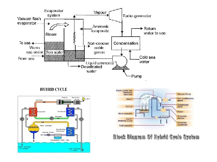
Types of OTEC system Open or Claude Cycle Combination of open & closed cycle in two concept Concept 1 Produce electricity + desalinated water Flash the water in a “flash evaporator” to produce “low pressure environment” Closed or Anderson cycle Maximize the use of OTEC Water evaporated in vacuum chamber Condensed back in ammonia evaporator to produce desalinated water Secondary fluid evaporated Hybrid cycle Produce electricity + desalinated water Concept 2: two times distillation water produced Electricity Generator Turbine
Advantage of OTEC Clean and environmental friendly Steady power supply without fluctuation Seasonal process (day and night, winter and summer) Desalination water