Objectives Air Distribution Systems Diffuser selection Duct design

Objectives - Air Distribution Systems - Diffuser selection - Duct design Reading Assignment: Chapter 18

• Near Human Body flow • • Diffuser flow https: //www. youtube. com/watch? v=LFg. Jn 75 Lh. Gc https: //www. youtube. com/watch? v=5 e 3 gixnm. Nz. M https: //www. youtube. com/watch? v=550 f. A 39 Ppb. Q

Computational Fluid Dynamics

CFD in Air Distribution Design Contaminant concentration in a kitchen
")
Buoyancy driven flow: Example of airflow in a stairway Heater (radiator)
")
Forced driven air flow Diffusers Linear diffusers Vertical Horizontal one side Grill (side wall) diffusers

Diffusers types Valve diffuser swirl diffusers wall or ceiling floor ceiling diffuser

Low mixing Diffusers Displacement ventilation

18. 7
 Qtot")
Diffuser Selection Procedure V = maximum volumetric flow rate (m 3/s, ft 3/min) Qtot = total design load (W, BTU/hr) Qsen = sensible design load (W, BTU/hr) ρ = air density (kg/m 3, lbm/ft 3) Δt = temperature difference between supply and return air (°C, °F) Δh = enthalpy difference between supply and return air (J/kg, BTU/lbm) • Select and locate diffusers, divide airflow amongst diffusers
")
Find Characteristic Length (L)

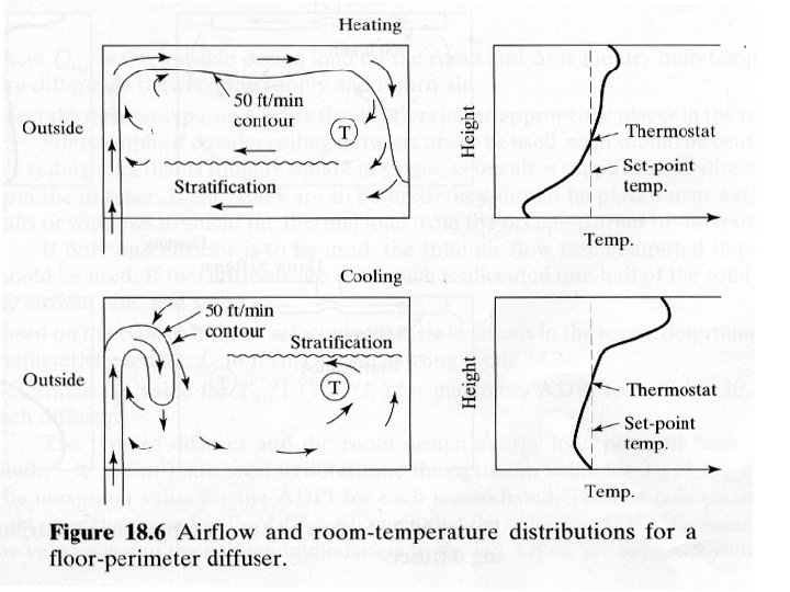
Indicator of Air Distribution Quality • ADPI = air distribution performance index • Fraction of locations that meet criteria: • -3 °F < EDT < 2 °F or -1. 5 °C < EDT < 1 °C • Where, EDT = effective draft temperature • Function of V and Δt (Eqn 18. 1) • EDT=(tlocal-taverage)-M(Vlocal-Vaverage) , M=7 °C/(m/s) ADPI considers ONLY thermal comfort (not IAQ)

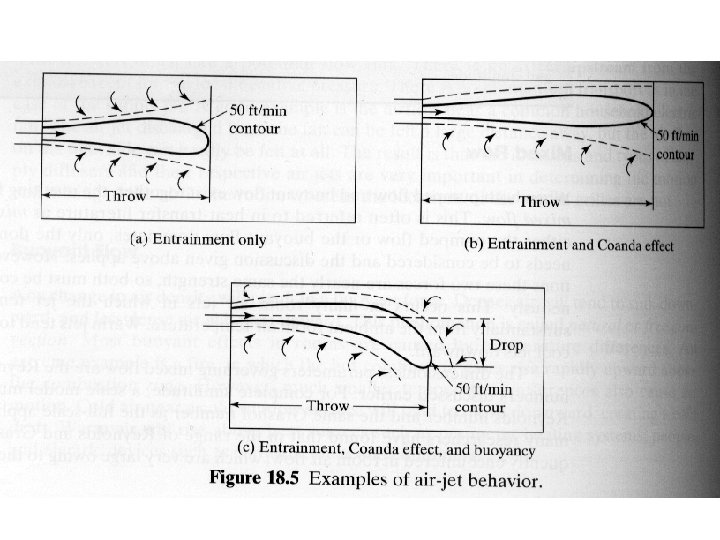
Ideal and Reasonable Throws

Select Register • Pick throw, volumetric flow from register catalog • Check noise, pressure drop
 2) 3) 4) 5) Find Q sensible total")
Summary of Diffuser Design Procedure 1) 2) 3) 4) 5) Find Q sensible total for the space Select type and number of diffusers Find V for each diffuser Find characteristic length Select the diffuser from the manufacturer data

Example 18. 3 • Qtot = 38. 4 k. BTU/hr • Δh = 9. 5 BTU/lbma

Pressures • Static pressure • Velocity pressure • Total pressure – sum of the two above

Relationship Between Static and Total Pressure

Duct Design • Total and static pressure drops are proportional to square of velocity • Plot of pressure drop vs. volumetric flow rate (or velocity) is called system characteristic

Frictional Losses

System Characteristic
- Slides: 23