Object Model Four main system objects or classes

Object Model: Four main system objects or classes • Controller object – might be made up of several controllers – is the brains of the system. – Takes input from the sensors and gives instructions to the actuators. • Sensor object – environmental objects that gives information to controller. – Can be passive (thermometer) or active (button).
 • Actuator object – Environmental objects that")
Object Model: Four main system objects (continued) • Actuator object – Environmental objects that are controlled by the controller. – Can be turned on or influenced by controller. – Examples: User indicator lights, motors, burners. • User Interface object – A display for the user. – Can be made up of both sensors and actuators. – Example: machine control panel

Step One: Develop a high-level object model Embedded System 0. . * Controller Sensor Button Actuator 0. . * User-Interface Pedal Inheritance Class Association 0. . * Class Name Zero or more Attribute() Aggregation Operation()

Review of Dynamic Model • A dynamic model is a type of state machine. • System can only be in one state at a time. • Arrows: Transitions – from one state to another happen – when events happen. • Events are labeled on the transitions. • Guards are conditions that keep a transition from happen, such as [is in neutral or park ]
![Step Two: Develop a systemlevel dynamic model ‘On’ button pushed [in neutral or park]](http://slidetodoc.com/presentation_image_h2/be40aeefcf57f5c1dad9da596e7dd846/image-5.jpg "Step Two: Develop a systemlevel dynamic model ‘On’ button pushed [in neutral or park]")
Step Two: Develop a systemlevel dynamic model ‘On’ button pushed [in neutral or park] Idle or off state State Transition [ condition ] Guard Running state ‘Off’ button pushed

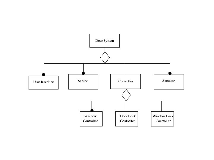
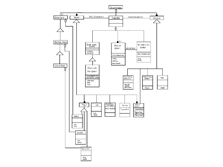
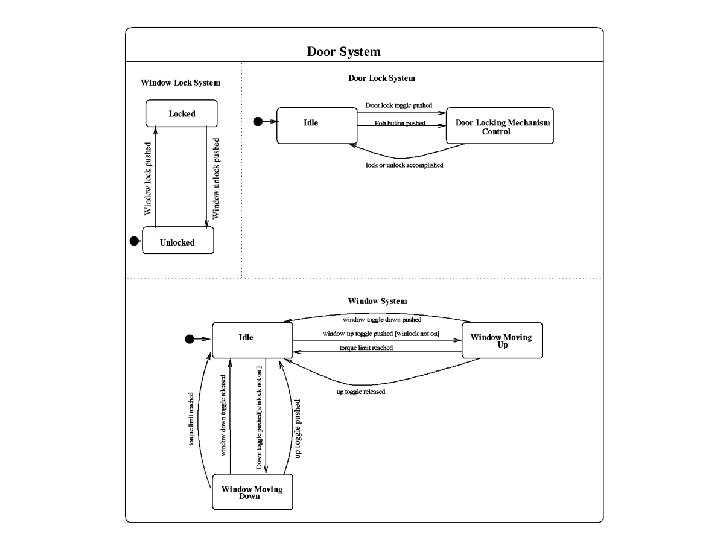
Example: Automotive Door Control • The system controls the windows and door locking functions. • All doors have window roll up and down controls. • Driver’s door has window lock feature. • Driver and front passenger have door lock and unlock toggle. • Fob unit for locking and unlocking doors, with driver notification (horn honk and lights flash. ) • Three concurrent systems identified.

Summary of development process • The object model shows the real world objects grouped in classes with attributes and operations and associations. • The dynamic model shows the control aspects with superstates refined into substates.

Review of Embedded Systems • Software controller that is interacting with its hardware environment through sensors and activators. • Concurrency and real time issues. • Safety critical nature of many of these systems. • Increased demand for these systems to be designed well.

High level design: Initial thoughts for embedded systems. • Assume there is a hardware environment. • Assume that somehow the needed signals are coming from the environment (sensors. ) • Assume the needed hardware is there to respond to your signals (actuators. )

Object Model Class attribute operation • In OMT the object model is the starting place for the modeling process. • The object model will include objects and their relationships. • The Object Model will be the static, structural aspect of the system.

Identify Real World Objects • Read over the problem description and find the nouns in the text. • These nouns are candidates for objects in your object model. • Discard unnecessary and incorrect classes. • Object classes will include the controller (software unit that will be built), sensors, and activators.

Data Dictionary: needs to be written • A written paragraph describing each modeling entity. • Needed so that names are non-ambiguous.

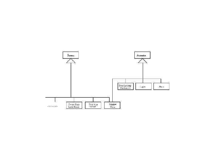
Class: Sensor • Because of the common properties of all sensors, this can be a class of objects, called a superclass. • Generalization - this superclass can be generalized into subclasses. • Inheritance - each subclass will inherit the properties or features from the superclass. • Examples: user interface (buttons etc), thermometers, hardware sensors.

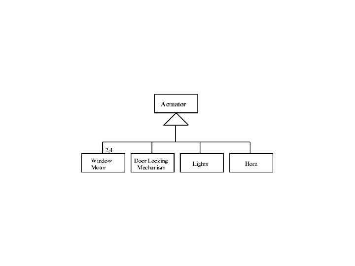
Class: Actuator • Similarly the activators will probably become a superclass. • Generalization - The various activators can be generalized into subclasses. • Inheritance - each activator subclass will inherit properties or features from the superclass. • Examples: LEDs, motor controls, etc.

The Controller • At an abstract level, this would be only one object in most embedded systems. • This object would be refined at lower levels of the modeling process into subsystems or sub-objects. • Aggregation could be used to show the parts of the controller.

Model itself Class attribute operation • Graphically a class is shown as a box with the name on top. • Attributes (middle third) and operations (bottom third) added eventually. • Attributes and operations are not needed for high-level object model.

Find the Associations • Interaction between objects must be shown by associations or lines draw with labels. – ex: line between user button and associated LED. • Many times these associations will be a physical connection between objects in an embedded system. • Help in Rumbaugh. (section 8. 4. 4 & 8. 4. 5) • Multiplicity must be shown eventually.

Example turned on by Actuators LED 0. . * Motor Controller reads 0. . * User buttons Sensors Water level

Conclusion about Object Model: • Look at Dr. Cheng’s ‘Creation Tips. ’ • Not very complex at first. • More details will come as designer proceeds from abstraction to more and more concreteness. – controller will be divided into more objects – attributes and operations are identified and included. • Starting place for OMT. Sets the stage.

Next step: Dynamic Model • The dynamic model shows the control aspect of the system. • Because embedded systems are mainly controllers, the dynamic model is the ‘key’ model for embedded systems. • This model can show the timing aspects. • Shows sequence of operations in response to external stimuli.

Getting started on a Dynamic Model • Helpful to make a scenario: – sequence of events that happens in one execution of a system. – Example: insert coins, make selection, pop dispensed. • Interface (high-level prototyping) – a rough draft of user interface will help thinking about the events in an embedded system.
 0 1 2 3 4 5 6 7 8")
Interface (type of rapid prototyping) 0 1 2 3 4 5 6 7 8 8 enter receipts clear cancel cash slot ATM interface from Figure 8. 17 by Rumbaugh

continue getting started…. • Next make an event trace. – each object is a vertical line. – events as horizontal arrow. – time goes from top to bottom. • Use Dr. Cheng's ‘creation tips. ’ • Follow the steps in Rumbaugh 8. 5.

Example of an Event Trace User ATM insert card request password enter password Consortium verify account OK Bank verify card with bank account OK request kind enter kind request amount enter amount process transaction process bank transaction succeeds Event trace for ATM scenario Example from Figure 8. 18 of Rumbaugh

More Dynamic Modeling

Dynamic Model - State Diagram • Graphical representation of a finite state machine. • Each ‘state’ represents all the values of the objects in the system. • Changing states - transitioning on events. • Events - external stimuli – ex. button pushed; timer complete; tub full.

Review of getting started: • Scenario making: gets us started thinking about events. • Interface (high-level prototyping): helps us to think about order of things. (happening in projects) • Event trace: helps to know what object is doing what action. • Dr. Cheng’s creation tips. • Use Rumbaugh’s 8. 5 section.

Dynamic Models for E. S. button pushed • Dynamic Model for user buttons would be on off button simplistic; modeling might not be needed. pushed • Some environmental units might have behavior that should be modeled. (like an engine shifting through speeds) • For embedded systems - might only need one significant behavior model (for controller. ) • Complex models will be decomposed into more detailed behavioral models. • Concurrency could be present within a model.

How dynamic model relates to object model • One state diagram for each class (with important behavior. ) • Each class has concurrent behavior. • Aggregation in the Object Model implies concurrency in the Dynamic Model.
 • Object model Car Ignition Transmission Brake Accelerator Each")
Examples of Aggregation (5. 17) • Object model Car Ignition Transmission Brake Accelerator Each class will need a concurrent state diagram
![Ignition Off turn key to start [Transmission in Neutral] release key Starting On turn](http://slidetodoc.com/presentation_image_h2/be40aeefcf57f5c1dad9da596e7dd846/image-36.jpg "Ignition Off turn key to start [Transmission in Neutral] release key Starting On turn")
Ignition Off turn key to start [Transmission in Neutral] release key Starting On turn key off Transmission push R push N Reverse Neutral push N Forward stop upshift First push F upshift Second downshift Third downshift Accelerator Off depress accelerator release accelerator Brake On Off depress brake release brake On

How to model concurrency within an object Car Ignition Off turn key to start [Transmission in Neutral] Starting push R push N Reverse Neutral push N Forward push F upshift First upshift Second Accelerator depress accelerator release accelerator Third downshift Off On turn key off Transmission stop release key Brake On Off depress brake release brake On

How to hide complexity • Not have a ‘flat’ state diagram • Start abstract and then do subdiagrams. – use bull’s eye • Take one abstract state and expand it with state generalization.
 coins in(amount) / set balance Idle")
Example of nesting (and other syntax as well) coins in(amount) / set balance Idle Collecting money coins in(amount) / add to balance cancel / refund coins [item empty] select(item) [change<0] do: test item and compute change [change=0] do: dispense item do: move arm to correct row do: move arm to correct column [change>0] do: make change do: push item off shelf Example: lower-level state diagram for Dispense item activity

State Generalization push R push N Reverse Neutral push F push N ex. level 0 Dynamic Model for a transmission. Forward Transmission push R push N Reverse Neutral push N Forward stop First upshift push F upshift Second downshift Third downshift ex. level 1 Dynamic Model for a transmission.

Notation on Transitions and in States • do: activity State 1 do: activity 1 event 1 (attribs) [condition 1]/ action 1 State 2 – takes some time. – associated with a state. • Guards – conditions - boolean – [ guard ] • Actions : – instantaneous – associated with an event. – /action You might need any or all of these for your project!

Checking for completeness and consistency • Formal specifications do this better! – The mathematical format can allow automation of these types of checks. • Every state should have a way in and out. – unless starting point or ending point. • Look for one object’s Dynamic Model sending an event that doesn’t have any receiving transition in another object’s DM.

Things to watch out for • Think about input from concurrent objects at unexpected times. – ex. If more than one ATM machine is trying to access the same account at the same time. – User input when not planned. (OK to ignore, but make sure that is what is really wanted. ) • Take your scenarios and see if they work! – Walk through seeing that all the object’s FM has all the needed transitions.

Topics Covered: • Dynamic Model – Synchronization schemes – Exception Handling – Timing including safety critical issues.

Synchronization • In concurrent processing, the actions of the objects are rarely independent of each other. • One may need to stop and wait for another process to ‘catch up’ or get to a certain state. • Example: In a nuclear power plant, the model would need to reflect waiting for rods to be in place before generating power.

Synchronization of States by status detection B A A 1 B 1 event A 2 [A is in state A 2] B 2 Transition between B 1 and B 2 will not fire until object A has entered state A 2.

Synchronization of States by a common event A B State. A 1 State. B 1 event 1 State. A 2 event 1 State. B 2 Firing of the two transitions in the two models will happen at the same time.

Synchronization of States by common data A B State. A 1 do: x: =0 event State. A 2 do: x: = 1 State. B 1 [x=1] State. B 2 Transition from State. B 1 to State. B 2 will not fire till State. A 2 has been done. (This assumes shared memory. )

Exception Handling • Events such as resets and hardware interrupts must be handled. • These are called Exceptions. • Crucial to terminate the behavior of an object. • Needed if user can exit a sequence of states at anytime.

Examples of exception handling • Possible to modeling exiting all the substates of a superstate in OMT. – Ex. Pushing the N (neutral button) in any of the forward states of a transmission. • 2 ways to exit: normal completion and exception. event 1 Superstate substate 1 exception event substate 2 normal exiting by completion

Timing Issues in Dynamic Model • Sometime the firing of a transition is time dependent, especially in embedded systems. • Real-time systems might have transitions that are tied to a real-time clock. • States might time-out after a certain length of time. • Transitions might need to be stalled for a certain length of time.
 • Safety critical real-time solutions – example: • transition out of")
Timing (Safety critical) • Safety critical real-time solutions – example: • transition out of ‘boiler on’ state after being in this state for 1 hour, even if one expects a transition on temperature>=expected. Boiler temperature >= expected On Off in ‘boiler on’ state >= 1 hour (Event on transition could just be labeled ‘ 1 hour’)

Delays in Dynamic Model • Sometimes a transition should not be fired for a certain amount of time. • This timing constraint can be modeled as a guard on transition – ex. • [10 seconds since the exit from state A] • This will delay the firing of the transition for 10 seconds.

More Timing Issues in D. M. • For a real-time system, the guard might refer to a real-time clock – example: • changing a traffic signal from day operation to night operation at 10 p. m. • because there is no event on transition: ready to fire when the guard is true. Day superstate [time = 2200 hours] [time = 0600 hours] Night superstate

- Slides: 55