OBJECT LOCALIZATIO N TECHNIQUES Presented by Anjali S


OBJECT LOCALIZATIO N TECHNIQUES Presented by Anjali S Dept of Oral Medicine &

CONTENTS � INTRODUCTION � INDICATIONS � CLASSIFICATION � INTRA ORAL LOCALIZATION TECHNIQUE � CONCLUSION

INTRODUCTION

INDICATIONS � IMPACTED � FOREIGN TOOTH. BODIES. � RETAINED ROOT /ROOT POSITIONS � UNERUPTED � SALIVARY � JAW /SUPERNUMERARY TEETH STONES. FRACTURES � ENDODONTIC � BROCKEN PROCEDURES- ACCESSORY CANALS NEEDLES & INSTRUMENTS

CLASSIFICATION INTRA ORAL LOCALIZATION TECHNIQUE STEREORADIOGRAPHY TUBE SHIFT TECHNIQUE RIGHT ANGLE TECHNIQUE MAGNIFICATION RADIOGRAPHY EXTRA ORAL LOCALIZATION TECHNIQUE RIGHT ANGLE TECHNIQUE TOMOGRAPHY SIALOGRAPHY LOCALIZATION TECHNIQUE BY COMBINATION OF INTRA ORAL & EXTRA ORAL RADIOGRAPHS

INTRA ORAL LOCALIZATION TECHNIQUES

STEREOSCOPIC RADIOGRAPHY • 1896 • Stereoscope - optical instrument for viewing photograph/roentgenogram which produce binocular vision PRINCIPLE : work as eye – brain merges them into one. INDICATION: �location of small intracranial calcifications & multiple foreign bodies in a dense or thick section �relationships of margins of bony fracture

PROCEDURE 2 exposure – one for each eye with definite distance apart called interpupillary distance Exposed film is viewed with stereoscope that use mirror/ prism to co-ordinate & converge the image to fuse one image. Drawback : Requires high level of skill

PARALLAX METHOD TUBE SHIFT TECHNIQUE PRINCIPLE The relative position of the radiographic images of two separate objects changes when the projection angle at which the projection was made is changed.

S AME L INGUAL O PPOSITE B UCCAL

METHOD Moving the tubehead mesially/distally or superiorly/infeiorly and changing the direction of the x-ray beam will result in the movement of the object of interest on the film in relation to the reference object.

ERROR tubehead is moved, but there is no change in direction of the xray beam, which results in no change in location of the object of interest in relation to reference object

HORIZONTAL PARALLAX METHOD Clark’s Rule Described in 1910 Used 2 periapical radiographs Keur used 2 OR rather than periapical radiographs Locate vertically aligned images eg: root canals

HORIZONTAL MOVEMENT • Patients head stabilized • A conventional intraoral radiographic image of area of interest • Second radiograph by shifting the PID either mesially or distally DISTAL MESIAL

Horizontal movement mesial tubehead is moved distally and the beam is directed mesially. distaltal distal mesial • buccal object of interest moves mesially (opposite to tubehead movement) in relation to the second molar • lingual object of interest moves distally (same direction as tubehead) in relation to the second molar.

VERTICAL PARALLAX METHOD � Richards in 1953 & 1980 -BUCCAL OBJECT RULE � Shift the tube in vertical plane � Used to locate horizontally aligned image. Eg-mandibular canal Radiographic localization of unerupted maxillary anterior teeth using the vertical tube shift technique: The history and application of the method with some case reports Stanley G. Jacobs American Journal of Orthodontics and Dentofacial Orthopedics October 1999

Vertical movement

Vertical movement of the tubehead and x-ray beam Maxillary PA BW Mandibular PA In moving from the maxillary periapical to the bitewing and from the bitewing to the mandibular periapical, the tubehead moves down and the beam is redirected upward (opposite direction; decreased vertical angulation).

APPLIED ASPECT OF TUBE SHIFT TECHNIQUE

INCISOR FILM CANINE FILM The maxillary left canine is impacted. Is it located more to the buccal or the lingual?

MOLAR BITEWING FILM MOLAR PERIAPICAL FILM The amalgam particle indicated by the arrows is located bucally or lingually?

1 st radiograph : radiolucency at the apex of the lower second premolar 2 nd : (disto-mesial) angulation To differentiate mental foramen from peri-apical lesions 3 rd: corono-apical angulation

RIGHT ANGLE TECHNIQUE MILLER’S TECHNIQUE PRINCIPLE 2 projections are taken at right angles to each other PROCEDURE 1 periapical radiograph superio-inferior & antero-posterior relationship 1 occlusal radiograph buccolingual & antero -posterior relationship Together gives 3 D of area and location of object

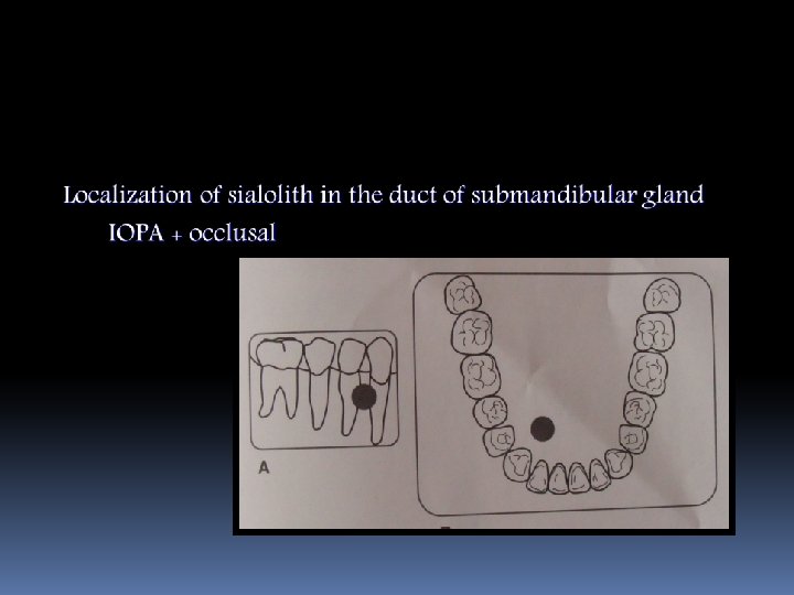
APPLIED ASPECTS 1. periapical + Occlusal two projections are taken at right angles to one another to localize the impacted tooth in or about the maxilla.

Periapical + Occlusal two projections are taken at right angles to one another to localize the impacted tooth in or about the mandible.

TECHNIQUE FOR MANDIBULAR 3 RD MOLAR 1. X-ray beam projected perpendicular to the occlusal film 2. Variation in technique- occlusal film placed in a slanting manner with its posterior border resting on ascending ramus

MODIFICATION OF MILLER’S TECHNIQUE FOR MAXILLARY 3 RD MOLAR � Superimposition of multiple skeletal structures in maxilla � Occlusal film horizontally placed with central ray passing through the zygomatic arch -another periapical film.

MAGNIFICATION RADIOGRAPHY PRINCIPLE OF IMAGE SIZE DISTORTION Focal spot – film distance object away from film more magnified and more distorted

APPLIED ASPECTS

- Slides: 34