Nuclear resonance scattering of synchrotron radiation and its

 · Nuclear Resonance Scattering of SR: Theory · Nuclear")

: machines dedicated to the")


, Hertz (1886) Veksler (1945) v/c <<")
 · Pre-accelerators: - LINAC: 100 ke. V electron gun Þ")
 · Insertion devices: wigglers and undulators. These are two arrays")
 · Undulators: weak magnetic field, narrow- band radiation from the")
 High-heat-load monochromator High-resolution")


:")


|2 Array of slits A(x) Diffraction pattern Illumination by")


 z y E x k B")


 size")


 scattering width around an AF reflection")
![Domain ripening: off-specular SMR, hard direction Mg. O(001)[57 Fe(26Å)/Cr(13Å)]20 2 Q @ AF reflection](https://slidetodoc.com/presentation_image_h2/3e68f07c9a61fcb1d6244d65b7d6c8fe/image-39.jpg "Domain ripening: off-specular SMR, hard direction Mg. O(001)[57 Fe(26Å)/Cr(13Å)]20 2 Q @ AF reflection")


 surface Additional EFG the surface one layer below the")

 Nuclear Resonant Scattering of Synchrotron")
- Slides: 45
Nuclear resonance scattering of synchrotron radiation and its applications in thin-film magnetism Dénes Lajos Nagy Wigner Research Centre for Physics, Hungarian Academy of Sciences and Eötvös Loránd University Budapest, Hungary Intensive Programme on Physics and materials science of nanostructures probed by nuclear methods and intense particle beams Leuven, Belgium, 14– 24 April 2013
Outline · Synchrotron Radiation (SR) · Nuclear Resonance Scattering of SR: Theory · Nuclear Resonant Scattering of SR: Experimental aspects · Thin-film applications · Nuclear Inelastic Scattering of SR: applications for nanostructures
Synchrotron radiation: History · SR: polarised electromagnetic radiation produced in particle accelerators or storage rings by relativistic electrons or positrons deflected in magnetic fields · First-generation SR sources ( 1965 - 1980): machines built for particle physics, SR produced at bending magnets is used in parasitic regime · Second-generation SR sources ( 1970 - 1990): machines dedicated to the applications of SR, radiation produced at bending magnets
Synchrotron radiation: History · Third-generation SR sources ( 1990 -): machines dedicated to the applications of SR, radiation produced both at bending magnets and at insertion devices - ESRF (Grenoble, France): 6 Ge. V - PETRA III (Hamburg, Germany): 6 Ge. V - APS (Argonne, USA): 7 Ge. V - SPring-8 (Harima, Japan): 8 Ge. V · The future: x-ray free-electron lasers (XFELs)
s ray s mic cos g- rar vis ed ible ligh t ult rav iole t x-r ays inf s ave o -r adi row mic fm ave s ow rad i r nuc leu pro s ton pro mo tein atolecule m us vir l cel ete 1 m SR in the electromagnetic spectrum
ESRF, Grenoble
Radiation field of radially accelerated electrons Maxwell (1864), Hertz (1886) Veksler (1945) v/c << 1 electron orbit acceleration v/c 1 electron orbit acceleration = E/m 0 c 2 1/ Polarisation E
Technical aspects (example: ESRF) · Pre-accelerators: - LINAC: 100 ke. V electron gun Þ 200 Me. V - booster synchrotron: 200 Me. V Þ 6 Ge. V · The storage ring: - circumference: 845 m; - number of electron buckets: up to 992; - electron bunch length: 6 mm Þ pulse duration: 20 ps and 100 ps at bending magnets and insertion devices, respectively; - re-acceleration power at I = 100 m. A: 650 k. W.
Technical aspects (example: ESRF) · Insertion devices: wigglers and undulators. These are two arrays of N permanent magnets above and below the electron (positron) beam. The SR is generated through the sinusoidal motion of the particles in the alternating magnetic field. · Wigglers: strong magnetic field, broad- band radiation from the individual poles is incoherently added. Intensity: ~ N. Horizontal beam divergence >> 1/.
Technical aspects (example: ESRF) · Undulators: weak magnetic field, narrow- band radiation from the individual poles is coherently added at the undulator maxima. Intensity: ~ N 2. Horizontal beam divergence ~ 1/. Wigglers, undulators electron beam synchrotron radiation
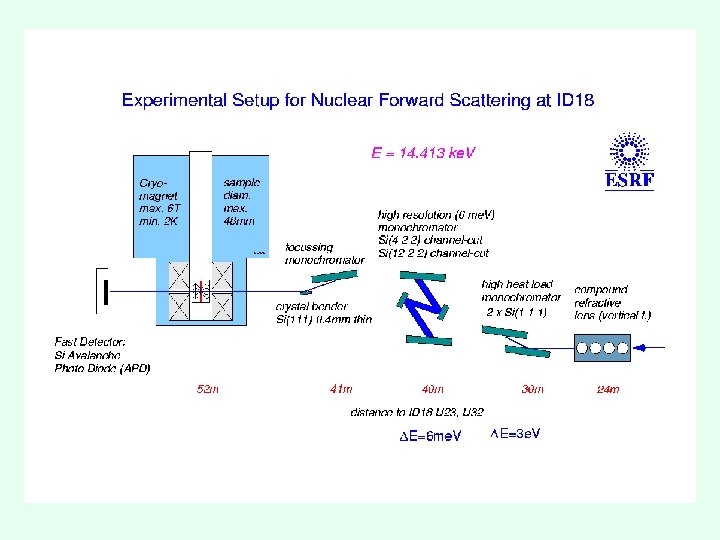
Energy bandwidth, monochromators Bragg monochromators U 23 at ID 18 (ESRF) High-heat-load monochromator High-resolution monochromator
Properties of SR · Tunable energy · High degree of polarisation · High brilliance · Small beamsize · Small beam divergence · Pulsed time structure
Hyperfine splitting of nuclear levels G 5 ne. V Ehf 100 ne. V Eg 14. 4 ke. V Ehf 100 ne. V 57 Fe
Nuclear resonance scattering of SR: Mössbauer effect with SR · E. Gerdau et al. (1984): first observation of delayed photons from nuclear resonance scattering of SR (at beamline F 4 of HASYLAB). · Basic problem: huge background from prompt non-resonant photons. The solution: - monochromatisation of the primary SR, - fast detectors and electronics.
Nuclear resonance scattering of SR: Mössbauer effect with SR · Hastings et al. (1991): first observation of delayed photons from nuclear resonant forward scattering of SR. · The bandwidth of SR is much larger than the hyperfine splitting. Þ All transitions are excited at the same time. Therefore the resultant time response is the coherent sum of the individual transitions (the amplitudes are added).
Nuclear resonance scattering of SR: Mössbauer effect with SR · Not only the different transitions of the same nucleus but also transitions of different nuclei (longitudinally within any distance and transversally within the transverse coherence length) are excited simultaneously and the scattering takes place coherently.
Nuclear resonance scattering of SR: Mössbauer effect with SR · The temporal interference of the amplitudes scattered from different hyperfine-split transitions leads to quantum beats. The strength of the hyperfine interaction is reflected in the frequency of the beating. · The orientation of the hyperfine field is reflected in the intensities of the different frequency components and in the depth of the beating.
Diffraction and quantum beats Intensity |A(q)|2 Array of slits A(x) Diffraction pattern Illumination by a spatially extended beam Position x Momentum transfer q Array of resonances A(E) Intensity |A(t)|2 Illumination by an energetically extended beam Time spectrum Energy E R. Röhlsberger Time t
Principle of a nuclear resonance scattering experiment H. Grünsteudel
Setup for a nuclear resonant forward scattering experiment The pulsed SR (left side, pulses separated by Dt) penetrates the sample and reaches the detector. The decay of the nuclear excited states, which takes place in the time window Dt (right side), reflects the hyperfine interactions of the resonant nuclei. H. Grünsteudel
Energy- and time-domain Mössbauer spectra 57 Fe 14. 4 ke. V Temporal beats R. Röhlsberger
Orientation of the hyperfine field The time spectra sensitively depend on the orientation of the Magnetization M relative to the Photon wave vector k 0 R. Röhlsberger
Orientation of the hyperfine field (the ”Smirnov figures”) z y E x k B z By E x k E z y B x k 1 2 3 4 5 6
Orientation of the hyperfine field O. Leupold
source sample detector
detector source sample Reflection geometry: depth selectivity
X-ray and Mössbauer reflectometry Relation between scattering amplitude and index of refraction:
X-ray and Mössbauer reflectometry: the scattering amplitudes µ electron density hyperfine matrix elements photoabsorption hyperfine energies
Mössbauer reflectometry: why at synchrotrons? · Due to the small (1 -2 cm) size of the sample and the small (1 -10 mrad) angle of grazing incidence, the solid angle involved in a Mössbauer reflectometry experiment is 10 -5 Þ only 1 photon from 106 is used in a conventional source experiment. In contrast, the highly collimated SR is fully used. · The linear polarisation of the SR allows an easy determination of the magnetisation direction.
Arrangement of an SMR experiment from the high-resolution monochromator z Q or w Hext qx-scan Qw-scan: /2 Q-scan: qz-scan 2 p/q xd= =1/D qxz y x APD E 2 Q k
Depth selective phase analysis with SMR Close to the critical angle of electronic total reflection, the penetration depth of hard xrays strongly depends on the angle of grazing incidence. For E = 14. 4 ke. V and iron: Q [mrad] 5 4 3 0 d [nm] 40. 5 20. 5 3. 5 1. 3
Depth selective phase analysis with SMR
Direction of the magnetisation in a Co/Fe/Co trilayer Monolayer resolution can be achieved by using the resonant isotope marker technique. Counts In a Co/Fe(7 ML)/Co trilayer, the magnetisation of the Fe layers at the Co/Fe interface is parallel while that of the internal Fe layers is perpendicular to the plane. Time after excitation (ns) (C. Carbone et al, 1999)
Antiferromagnetic coupling in a Fe/Cr multilayer Fe Cr Layer magnetisations:
Patch domains in AF-coupled multilayers Layer magnetisations: The ‘magnetic field lines’ are shortcut by the AF structure ® the stray field is reduced ® no ‘ripple’ but ‘patch’ domains are formed.
The off-specular scattering width · The off-specular (diffuse) scattering width around an AF reflection stems only from the magnetic roughness. · The diffuse scattering width D Qx at an AF reflection is inversely proportional to the correlation length x of the layer magnetisation: x = 1/D Qx At an AF reflection, x is the average domain size!
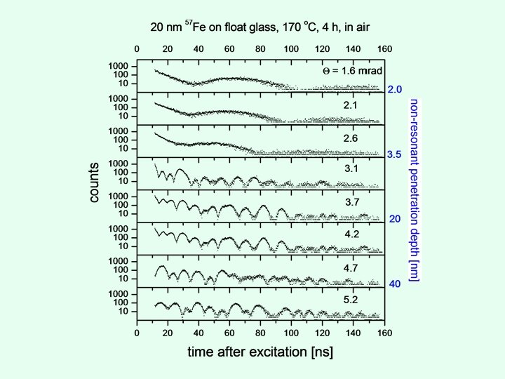
Domain ripening: off-specular SMR, hard direction Mg. O(001)[57 Fe(26Å)/Cr(13Å)]20 2 Q @ AF reflection Correlation length: x = 1/Dqx x 370 nm x 800 nm ESRF ID 18
Nuclear inelastic scattering H. Grünsteudel
Nuclear inelastic scattering on a-57 Fe DOS A. Chumakov, R. Rüffer
Phonons in iron: from the bulk to a strained epitaxial monolayer a-57 Fe on W(110) surface · 1 ML: pseudomorphic growth; 10 % stretching. · High-energy modes appear from 10 ML. · 40 ML: bulk-like DOS; the shift of 1 me. V results from the 2 % volume expansion. S. Stankov et al. DOS ESRF ID 18
Phonons at the Fe (110) surface Additional EFG the surface one layer below the surface Bhf || k deeper [110] 57 Fe/56 Fe T. Ślęzak et al. isotope marker technique ESRF ID 18
Vibrational properties of nanograins and interfaces in nanocrystalline Fe 90 Zr 7 B 3 Thin interface vibrates together with the grains. S. Stankov et al. ESRF ID 18
Reference E. Gerdau and H. de Waard (eds. ) Nuclear Resonant Scattering of Synchrotron Radiation special volumes 123/124 and 125 of Hyperfine Interactions (1999 -2000)