NUCLEAR REACTOR MATERIALS 3 LIGHT WATER REACTOR FUEL


 Contact to fuel rod with 3 point support. The axial")


")

 a side about 14 cm,thickness 2 -3 mm, length about 4")
 The water rods were introduced to enhance the neutron moderation in")


 fuel has been used in")


, a strong alpha emitter and a source of spontaneous")

 MOX for LWRs contains several % fissile")


 is not itself fissile but it is ‘fertile’")


 conduction through lattice vibrations")


 is")


 accumulation Solid FP swelling")


 Splitting of the fissile nucleus into two fragments in the")
 by fission 2. Nucleation of gas bubbles")


 of pellet where local burnup is very")


")


 γ Scanning Measurement The γ scanning measurement was conducted to confirm the")
 Measurement of Dimensions Figure shows the measurement results of the fuel rod")
 Measurement of FP Gas Release Rate The puncture test was conducted to")
 Cladding Oxide Film Thickness and Hydrogen Content The oxide film thickness on")
 Cladding Mechanical Properties The tensile test by using the dog-bone shape specimen")


 Rod Internal Pressure")

- Slides: 117
NUCLEAR REACTOR MATERIALS 3. LIGHT WATER REACTOR FUEL
In this Chapter 1. Fuel behaviour 2. Testing and Instrumentation
Fuel behaviour
Characteristics of nuclear fuel pellet To produce energy continuously Atomic density of nuclear fissile material, and nuclear properties of chemical compound must be advantageous for continuity of nuclear reaction. To transfer the produced energy to coolant To transfer the energy as thermal energy to coolant effectively, nuclear fuel must have high thermal conductivity. Work as the first wall for radioactivity To be stable physically and chemically at high temperature use, defects formation by irradiation must be low.
Major nuclear fission reaction in reactor
Fission energy and burnup At one nuclear fission, about 210 Me. V is produced, and about 195 Me. V is used as thermal energy. About 30% of fission energy is converted to electricity at a nuclear power plant.
Type of commercial Reactor and fuel form
Composition of natural Uranium U-235 0. 72% U-238 99. 28% U-234 0. 006% About 3 -5% enriched UO 2 is used for LWRs
Physical/chemical form of nuclear fuel material
Fundamental property of nuclear fuel material
Fuel Behaviour Fuel behavior = comprehensive interaction of many factors ・temperature ・neutron flux ・fission:heat generation, Fission Products accumulation ・micro and macro
Why fuel behaviour is important To keep the integrity of fuel rod and assembly until the designed burnup(life limit) Complicated interactions : (experience is important) ・it is sometimes difficult to predict with theoretical/ deterministic model ・cannot be treated as reactor physics by theoretical model ・metallurgical structure sensitivity ・many unknown factors, irradiation experiment is important.
Phenomena occur during rector operation
Changes in fuel with burnup increase
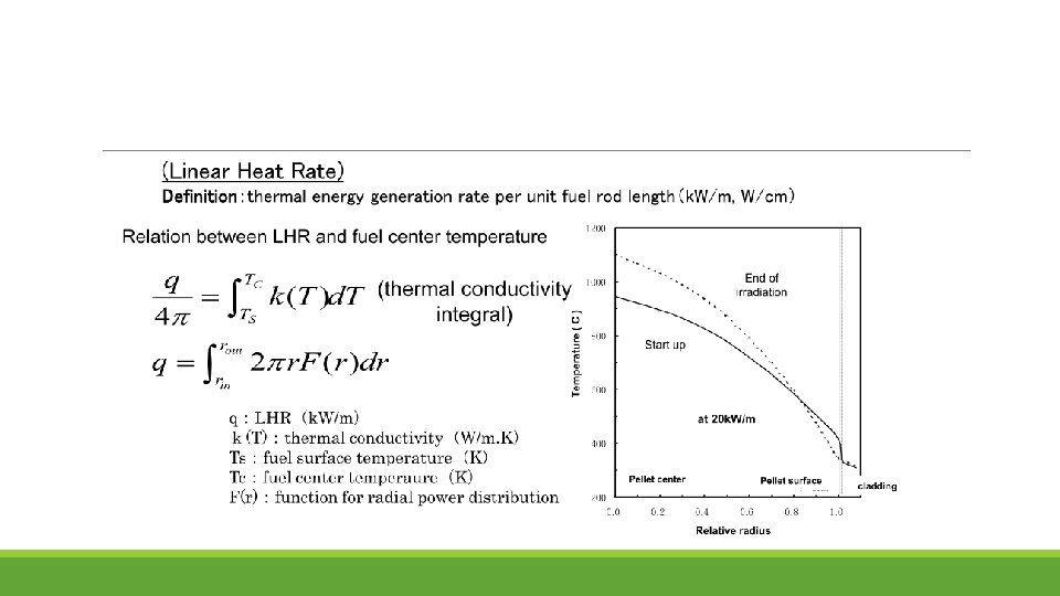
Special unit for nuclear fuel
Structure of fuel assembly
Fuel assembly framework Nuclear fuel designs dictate that the pellet-filled rods have a precise physical arrangement in terms of their lattice pitch (spacing), and their relation to other features such as water (moderator) channels and control-rod channels. Characteristics: Resistant to chemical corrosion, high temperatures, large static loads, constant vibration, fluid and mechanical impacts. They must also be as neutron-transparent as possible.
Assembly structures comprise a strong framework made from steel and zirconium upon which are fixed numerous grid support pieces that firmly hold rods in their precise lattice positions. These are made from zirconium alloy and must permit (and even enhance) the flow of coolant water around the fuel rod. The grid structures grip the fuel rod and so are carefully designed to minimise the risk of vibration-induced abrasion on the cladding tube – called ‘fretting’ wear.
In order to maximize the efficiency of the fission reaction the cladding and indeed all other structural parts of the assembly must be as transparent as possible to neutrons. Different forms of zirconium alloy, or zircaloy, are therefore the main materials used for cladding. This zircaloy includes small amounts of tin, niobium, iron, chromium and nickel to provide necessary strength and corrosion resistance. Hafnium, which typically occurs naturally with zirconium deposits, needs to be removed because of its high neutron absorption cross-section.
PWR Fuel Assembly In PWR fuel assembly, thimble tubes and grids are main framework
General Assembly Fuel for western PWRs is built with a square lattice arrangement and assemblies are characterized by the number of rods they contain, typically, 17× 17 in current designs A PWR fuel assembly stands between four and five metres high, is about 20 cm across and weighs about half a tonne. An 1100 MWe PWR core may contain 193 fuel assemblies composed of over 50, 000 fuel rods and some 18 million fuel pellets. Once loaded, fuel stays in the core for several years depending on the design of the operating cycle.
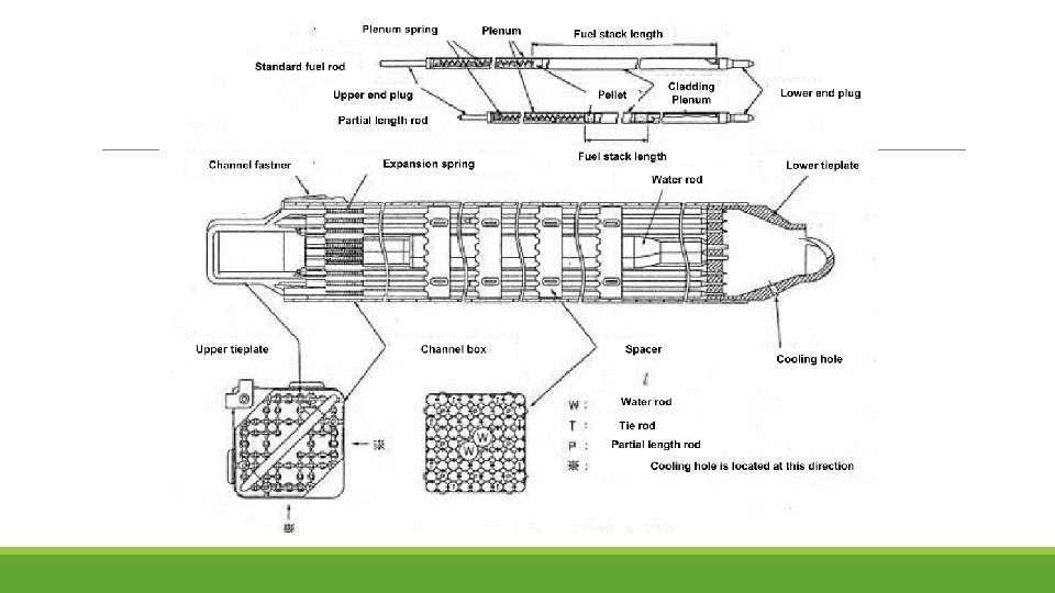
Structure of fuel rod
Structure of fuel assembly
Structure of grid (spacer) Contact to fuel rod with 3 point support. The axial elongation/shrinkage of fuel rods are allowed
Structure of BWR core §Core consists of units which have one control rod surrounded by 4 fuel assemblies §Fuel assembly sits on core support and the top of the assembly is supported with upper lattice plate
In BWR fuel assembly, water channel, fuel rods and spacer are main framework.
• Pellets are installed in Zr liner cladding and welded with both end plugs with 10 bar He filler gas. • Important design parameters: pellet density, gap size, plenum volume, cladding thickness, He pressure, etc. Number in this figure is size for BWR/4, BWR/5 and ABWR (m)
Cross section of Control Rod(BWR)
Characteristics of BWR Fuel Assembly • Four fuel assemblies and a cruciform shaped control blade form a 'fuel module' • each assembly is isolated from its neighbours by a water-filled zone in which the cruciform control rod blades travel (they are inserted from the bottom of the reactor) • each BWR fuel assembly is enclosed in a zircaloy sheath or channel box which directs the flow of coolant water through the assembly and during this passage it reaches boiling point • BWR assemblies contain larger diameter water channels – flexibly designed to provide appropriate neutron moderation in the assembly.
Channel box (BWR) a side about 14 cm,thickness 2 -3 mm, length about 4 m : rectangular tube made of zircaloy-4 Role of channel box ・ keep the coolant flow space for assembly ・ keep the space for CR insertion ・ protection of fuel during handling ・ Use for shipping test in reactor(leak fuel test)
Water rods(Water channel) The water rods were introduced to enhance the neutron moderation in the central region of assembly and to increase the fission of the fuel. The non-boiling coolant water flows in the water rods(or water channel) located in the center of the fuel assembly. The diameter of water rods increased with the enrichment-increase for high burnup use of fuel, to increase the water/ fuel volume ratio within the channel.
Guideline for fuel design o Fuel assembly should be designed to keep the integrity regardless the various factors which occur during the in-rector operation. § pressure difference between outside and inside of the rod § irradiation of fuel or other material § changes of pressure/temperature due to change of load § chemical effects § static/dynamic load § deformation of pellet § gas composition change in fuel rod o Fuel assembly should be designed not to deform excessively during transportation or handling.
Mechanical design of fuel rod Requirement Cladding should not be failed during abnormal transient in operation (cladding should not be failed systematically with penetrated defects by mechanical load) Conditions to prevent the fuel failure due to over strain, “average circumferential strain of cladding should be below 1%” In the safety evaluation during the abnormal transient in operation, the evaluated maximum LHR should not exceed the LHR for margin safety.
Evaluation of BWR fuel rod design BWR fuel rod is designed under the following standards based on the guideline for safety design judgment. (1) average circumferential plastic strain of cladding should be less than 1%. (2) the stress in the cladding should be less than acceptable stress. (3) Accumulated fatigue coefficient should be less than 1.
Design criteria for PWR fuel Fuel center temperature should be below the melting point of UO 2 Pressure in the rod should not exceed the limit to open the closed gap between cladding/pellet due to the creep deformation of cladding outward, during normal operation. The stress in the cladding should be less than yield strength of Zirconium alloy(zilcaloy-4) The circumferential extension strain of cladding during abnormal transient should be less than 1%. Accumulated fatigue coefficient should be less than designed life limit.
Characteristics of reactor core and fuel in PWR and BWR
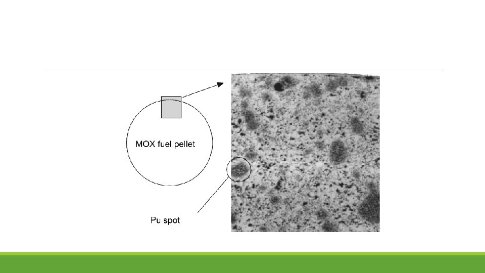
MOX Fuel Mixed uranium oxide + plutonium oxide (MOX) fuel has been used in about 30 light-water power reactors in Europe and about ten in Japan It consists of depleted uranium (about 0. 2% U-235), large amounts of which are left over from the enrichment of uranium, and plutonium oxide that derives from the chemical processing of used nuclear fuel (at a reprocessing plant). This plutonium is reactor-grade, comprising about one third non-fissile isotopes.
Advantages of MOX The use of up to 50% of MOX does not change the operating characteristics of a reactor, though the plant must be designed or adapted slightly to take it. A significant advantage of MOX is that the fissile concentration of the fuel can be increased easily by adding a bit more plutonium MOX use also becomes more attractive as the need to reduce the volume of spent fuel increases. Seven UO 2 fuel assemblies give rise to one MOX resulting in only about 35% of the volume, mass and cost of disposal.
Handling of Pu Plutonium from reprocessed fuel is usually fabricated into MOX as soon as possible to avoid problems with the decay of short-lived plutonium isotopes. ◦ In particular, Pu-241 (half-life 14 years) decays to Am-241 which is a strong gamma emitter, giving rise to a potential occupational health hazard if separated plutonium over five years old is used in a normal MOX plant. ◦ The Am-241 level in stored plutonium increases about 0. 5% per year, with corresponding decrease in fissile value of the plutonium.
Pu-238 (half-life 88 years), a strong alpha emitter and a source of spontaneous neutrons, is increased in high-burnup fuel. Pu-239, Pu-240 and Pu-242 are long-lived and hence little changed with prolonged storage. Pu-239, a fissile isotope that is the second most used nuclear fuel in nuclear reactors after U-235, and the most used fuel in the fission portion of nuclear weapons, is produced from U-238 by neutron capture followed by two beta decays. To late 2014, Areva had reprocessed more than 13, 000 tonnes of used fuel and recycled 130 tonnes of plutonium into MOX. From this, it has delivered 4000 MOX fuel assemblies for its 24 reactors licensed to use it.
Recycling of MOX Used MOX fuel reprocessing has been demonstrated since 1992 in France, at the La Hague plant. In 2004 the first reprocessing of used MOX fuel was undertaken on a larger scale with continuous process. Ten tonnes of MOX irradiated to about 35, 000 MWd/t and with Pu content of about 4% was involved. Since 2004 an increasing amount of MOX from German and Swiss reactors has been reprocessed, totaling about 70 tonnes, with a wide range of composition. As MOX is repeatedly recycled it is mixed with substantial proportions (70 -80%) of plutonium from UOX fuel.
Fuel behavior of MOX (use for LWRs) MOX for LWRs contains several % fissile Pu; ①Thermal conductivity is a little lower than that of UO 2. ②Fission gas release is a little larger than that of UO 2 ③Creep rate is larger than that of UO 2 ④Melting point decreases.
Emerging Fuel-Thorium exists in nature in a single isotopic form – Th-232 – which decays very slowly. The decay chains of natural thorium and uranium give rise to minute traces of Th-228, Th-230 and Th-234, It decays eventually to lead-208. Compared to UO 2 , Thorium oxide (Th. O 2) • relatively inert and does not oxidise further • has higher thermal conductivity and lower thermal expansion • much higher melting point • Much lower fission gas release in nuclear reaction
Estimated world thorium resources Country Tonnes India Brazil Australia USA Egypt Turkey Venezuela Canada Russia South Africa China Norway Greenland Finland Sweden Kazakhstan Other countries 846, 000 632, 000 595, 000 380, 000 374, 000 300, 000 172, 000 155, 000 148, 000 100, 000 87, 000 86, 000 60, 000 50, 000 1, 725, 000 World total 6, 355, 000 IAEA-NEA publication Uranium 2014: Resources, Production and Demand
Thorium as Nuclear Fuel Thorium (Th-232) is not itself fissile but it is ‘fertile’ and upon absorbing a neutron will transmute to uranium-233 Th-232 is first irradiated in a reactor to provide the necessary neutron dosing to produce protactinium-233. The Pa-233 that is produced can either be chemically separated from the parent thorium fuel and the decay product U-233 then recycled into new fuel, or Thorium fuels therefore need a fissile material as a ‘driver’ so that a chain reaction (and thus supply of surplus neutrons) can be maintained. The only fissile driver options are U-233, U-235 or Pu-239
key benefits of Thorium cycles exclusively allow thermal breeder reactors. ◦ More neutrons are released per neutron absorbed in the fuel in a traditional (thermal) type of reactor. This means that if the fuel is reprocessed, reactors could be fueled without mining any additional U-235 for reactivity boosts The Th-U fuel cycle does not irradiate Uranium-238 and therefore does not produce transuranic (bigger than uranium) atoms ◦ like Plutonium, Americium, Curium, etc. These transuranics are the major health concern of long-term nuclear waste. Thus, Th-U waste will be less toxic on the 10, 000+ year time scale. Thorium is more abundant in Earth’s crust than Uranium
Experiments in a Norwegian underground plant could lead to the radioactive element thorium being developed as a safer alternative in the production of nuclear power.
Temperature effect of Fuel Behaviour Temperature distribution in fuel rod and changes due to irradiation(burnup) Temperature depends on gap width and LHR. Temperature⇔deformation⇔gap pellet deformation (thermal expansion, densification, creep) cladding deformation(ridging, creep down) Temperature⇔structure change (accumulation of fission products: thermal properties change)
Thermal Analysis Thermal analysis providing local temperatures and temperature gradients that are of relevance for complex thermal, mechanical, physical and chemical processes The thermal analysis in a fuel rod is governed by the heat conduction equation: thermal conductivity =λ, specific heat = c, density =ρ and the local power density=q′′′
Thermal conductivity of LWR fuel Three contributions are identified: i) conduction through lattice vibrations , ii) conduction through free electrons and iii) a small contribution due to radiation. At lower temperatures the phononic term dominates. At higher temperature the electronic contribution is more significant Together, both contributions lead to a minimum of the total thermal conductivity λ at temperatures around 2000 K. Beside the dependence on the temperature, thermal conductivity of UO 2 depends on the porosity P, the oxygen-to-metal ratio O/M (stoichiometry) and the burnup (rim zone)
a. The effect of porosity Porosity in a ceramic material decreases thermal conductivity. Geometry (morphology, size, shape, orientation) and physical properties (emissivity of the solid, properties of the gas trapped inside the pores) are of importance. b. The effect of stoichiometry Hypo- and hyperstoichiometric fuel has a lower thermal conductivity than stoichiometric fuel since introducing point defects (vacancies or interstitials) increases phonon scattering.
c. The degradation effect of burnup the burnup effect consists of two contributions: a general degradation in thermal conductivity of the fuel and the development of the “rim zone” which may act as a thermal barrier.
Radial temperature distribution The fuel center temperature during normal operation is around 1000 C in LWRs.
Heat transfer coefficient The heat transfer coefficient between fuel and cladding (gap conductance) is one of the important contributors defining the temperature of the fuel. Gap conductance models depend on temperature, gas composition, gas and contact pressure on surface morphology (roughness, waviness) Two situations must be taken into considerations: § Low burnup § High burnup
Irradiation effects on thermal conductivity
Fuel on power conditions
Cracking, thermal expansion and relocation of pellet
PCMI : Pellet-Clad Mechanical Interaction
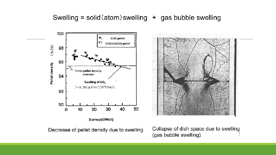
Densification/Swelling Densification Pores from manufacturing shrink/disappear due to the fission fragments passage, and the density of UO 2 pellet increases. Mainly occurs, at low temperature less than 1000 C and low burnup less than 10 GWd/t.
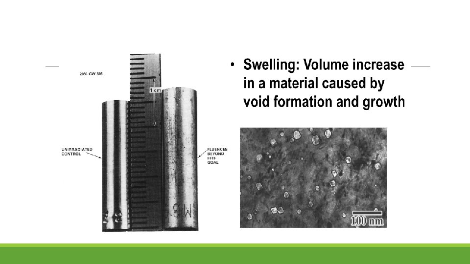
Swelling Density of UO 2 decreases due to FPs(Fission Products) accumulation Solid FP swelling ・ Precipitation or solution of solid FPs in UO 2 matrix ・ Independent of irradiation conditions(temperature) FP gas bubble swelling ・ Gas bubbles grow in grain or grain boundary ・ Strongly depends on irradiation conditions(temperature, rod power)
Accumulative effects of fission and structure change of pellet ①change of radial power density distribution in pellet ◦ accumulation of FPs(solid atoms, gas atoms) and irradiation defect ②formation of fission gas bubbles and fission gas release ③swelling ④degradation of thermal conductivity of pellet ⑤formation of rim structure ⑥change of O/M ratio ◦ consumption of oxygen due to inner surface oxidation of zircaloy cladding
Restructuring of pellet Cracking and relocation of pellet Cracking during power up (from outer to inner) Cracking during power down(from inner to outer, stop at circumferential cracks) Phenomenon of gap width reduction due to radial movement of pellet fragments(relocation)
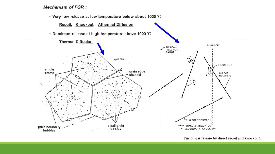
Fission gas release (FGR) Splitting of the fissile nucleus into two fragments in the doublet distribution of mass numbers occur in the regions 90 - 100 and 140, thus giving high yield to the rare gas species krypton and xenon and the volatile species iodine and caesium. Consequence: • clad integrity is challenged • Krypton and xenon have lower thermal conductivities than helium, the release of these gases also causes worsening in the pellet-clad gap conductance and increased fuel temperatures.
FGR Mechanisms 1. Production of gases(Xe, Kr) by fission 2. Nucleation of gas bubbles in matrix 3. Growth of gas bubbles by atomic migration of fission gas atoms to existing bubbles. 4. Re-solution of the gas atom within the bubble. 5. Migration of the bubbles, either as a randum-walk process in the absence of directed forces acting on the bubble or as biased motion when such forces are present. 6. Coalescence of bubbles moving either in a random or directional fashion. 7. Interaction of bubbles with the crystal defects(dislocation and grain boundaries). 8. Release of fission gases, either to external surface or internal surface such as grain boundaries. When the bubbles on grain boundaries become sufficiently large and numerous, they can link up and release gas to one of the external surface. 9. Release of fission gas by direct flight of energetic fission fragments out of an external surface. (small and significant only at low temperature. )
FGR at higher Burnup In the centre of the pellet some diffusion can occur and fission gases diffuse from the bulk of the grains to the grain boundaries. When the temperature is high enough, bubbles will nucleate, grow and interlink for the gas to escape. At intermediate temperature (700 -800 °C), thermal activation is too low to allow bubble nucleation and the limited amount of fission gas, that diffused to grain boundaries, is trapped by the grain boundaries and remains as segregated atoms. This segregation embrittles the grain boundaries and enhances intergranular fracture induced by any thermal stress.
Fission gas bubbles on grain boundary
Fission Product Swelling At the start of irradiation, there is a contraction in volume as pores remaining from the sintering process continue to shrink. This is most pronounced in low density fuel, especially if the porosity is small, typically less than one micron diameter. This process quickly saturates and is followed by a monotonic increase in volume as more and more fission products take the place of the fissionable uranium. This swelling has several identifiable components: 1. solid fission products, 2. fission gas as individual atoms, 3. fission gas precipitated into intragranular bubbles, 4. fission gas in intergranular bubbles ( situated on grain boundaries).
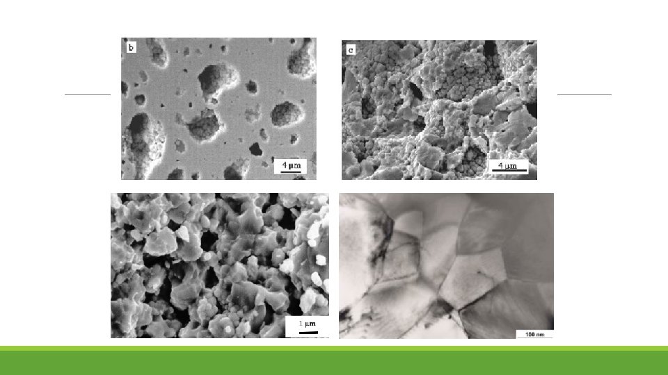
Rim structure Formed at pellet rim at high burnup. Appears at local burnup above 70 GWd/t. Porous structure in which large gas bubbles of several μm size are surrounded by subdivided small grains(about 0. 1μm ).
Rim structure appears at outer periphery(rim) of pellet where local burnup is very high. ◦ Production of 239 Pu due to resonance neutron absorption of 238 U at rim and burning of 239 Pu Formation of rim structure(proposed model) • Subdivision of grain(polygonization) by irradiation defects, and accumulation of gas bubble • Subdivision of grain and recrystalization by irradiation defects, sweep of gas bubble and accumulation of gas bubble • Recrystalization due to high pressure in the gas bubbles.
Stress Corrosion Cracking This type of failure was generic to zirconium alloy clad fuel that was subjected to significant power increases. It is grouped with other types of pellet-clad-interaction (PCI) failure mechanisms observed to occur in zirconium alloy fuel cladding it was evident that the concurrence of four factors was necessary for the failure to take place: sufficient stress, sufficient time, a susceptible material and the presence of the right chemical environment.
a. Sufficient stress With increasing power, the pellet thermal expansion leads to an increase in the pellet diameter, i. e. a departure from the initial cylindrical shape, and cracking of the pellet periphery. Also, during normal fuel handling, small UO 2 chips can relocate to the space between the pellet surface and the clad. All these processes, independently or in combination, can increase the stress in the cladding. In addition, the geometry of the cladding (wall thickness-to-diameter ratio), its creep rate under reactor operating conditions, and the presence of flaws on the internal clad surface all contribute to produce the resultant stress field.
b. Sufficient time The time to failure was divided into two periods: an incubation time and a propagation time. The incubation time was the period required for the formation of incipient cracks. The propagation time was the time required for these cracks to grow through the clad wall thickness.
c. Susceptible material After a critical irradiation dose, the positive effects of the clad metallurgical properties disappear and all materials become about equally susceptible to cracking. Two types of protective layers have been extensively studied and implemented in fuel fabrication; a lubricant and chemical barrier (graphite) that is applied as an internal coating after tubing fabrication a metallic barrier (zirconium) that is applied in the form of an internal thin layer as part of the tube fabrication process for BWR fuel.
d. Chemical environment iodine was first targeted as the chemically-active species due to its high yield, volatility and known properties of the halogens in causing SCC Cs and/or Cd were both capable of cracking zirconium alloys, with a mixture of these species being more potent than either one by itself. The presence of other species can act as either inhibitors or promoters. Graphite can act as a strong inhibitor. The replacement of graphite by siloxane as a chemical coating has proved to be even more effective. Oxygen has also been proved to be an effective inhibitor that may restore the protective oxide layers on most of the regions that are sensitive to the chemical attack. The presence of iron and organic iodides significantly increase the frequencies of crack initiation and shorten times to failure, thereby classifying them as promoters
Characteristics of fuel cladding � High corrosion resistance at outer surface � Adaptability for pellet deformation(swelling, thermal expansion) � SCC resistance of inner surface � Small thermal neutron absorption cross section � Mechanical strength as structural material � High film coefficient of heat transfer from pellet to coolant � Integrity and easy machining as parts
low thermal neutron cross section and high melting point are important In FBR, mechanical strength at high temperature is important and thermal neutron cross section is not so important.
Composition of various zirconium alloy
New zirconium alloy
Creep strength of cladding materials
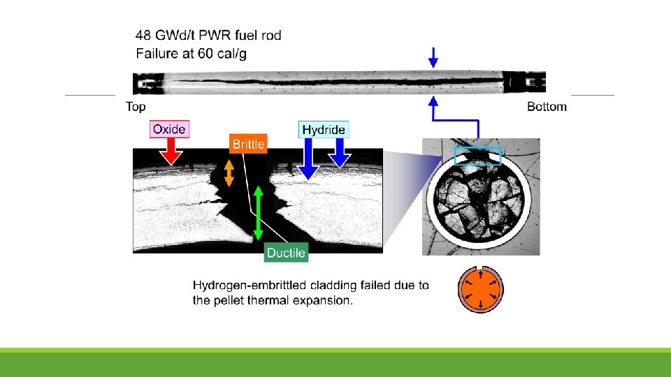
Hydrogen distribution in the cladding The hydrogen generated in the cooling water diffuses through the zirconium oxide layer into the Zircaloy. The build-up of a hydrogen concentration at the outer surface causes a hydrogen flow to the inner side of the cladding. The result is a gradient in the hydride concentration across the clad wall. The hydride structure depends on the temperature history, especially during cooling down (shutdown of the reactor).
At room temperature hydrogen in Zircaloy cladding is mainly present as radial and/or circumferential zirconium hydrides throughout the cladding thickness. At operational temperatures between 300°C and 400°C and at hydrogen concentrations higher than the solubility limit, zirconium hydrides will be formed predominantly at the outer interface Zircaloy-Zr. O 2 The effect of the amount of hydrogen on the mechanical properties of the cladding depends largely on the size and orientation of the zirconium hydrides platelets formed and on the presence of stresses in the cladding
Water side corrosion of cladding and accumulation of hydride
Weight gain curve of cladding oxidation Fine oxide film formed at interface of oxide and metal, works as protective film. Repeated formation and destruction of protective film result in linear weight gain. The destruction of protective oxide film is caused by the compressive stress in the film due to volume increase by oxidation.
Improvement of water corrosion resistance of zirconium alloy
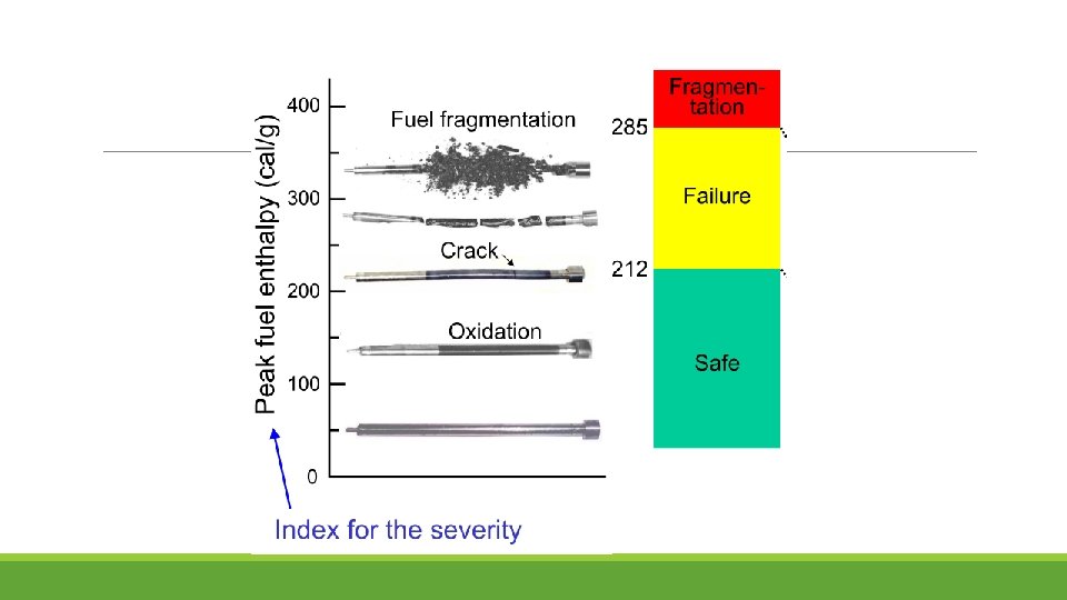
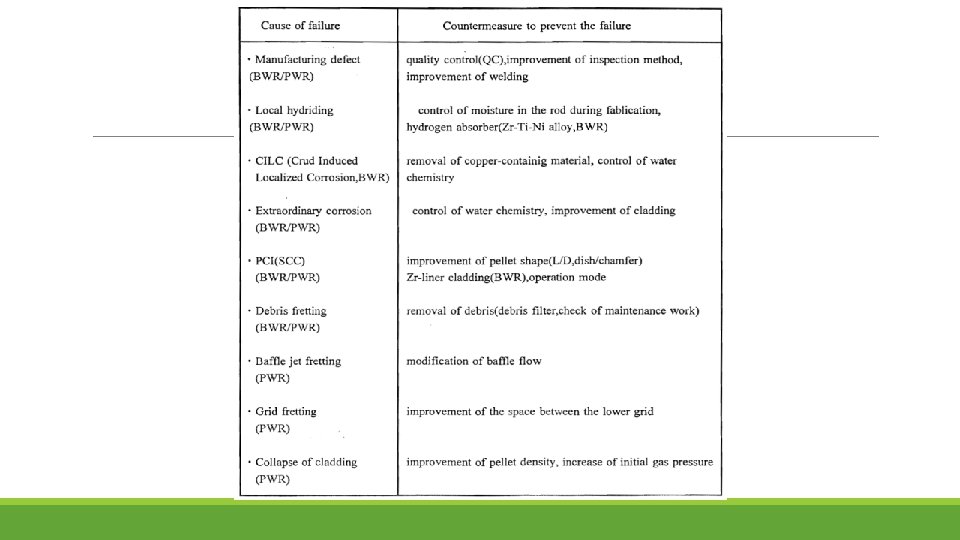
Fuel failure
Pellet Cladding Interaction (PCI)
Pellet shape and ridging deformation
Development of high burnup fuel To Improve of economics- reduction of fuel cycle cost, high burnup use-reduction of spent fuel Effective use of resources: use of plutonium as MOX fuel in LWR
Testing and Instrumentation
Introduction Requirements for enhanced reactor safety and efficiency make it necessary to perform precise in- and post-reactor experiments and, consequently, to use more up-to-date measurement equipment and analysis techniques, thus developing hot labs and research reactor facilities. Non destructive and destructive PIE techniques used for investigation of water reactor fuel. Recent practices in high burn up fuel investigation revealed the importance of advanced PIE techniques, such as 3 -D tomography, secondary ion mass spectrometry and scanning electron microscopy. Advanced in-pile measurement techniques for better understanding of the mechanisms of fuel behaviour under irradiation.
Hot Cell
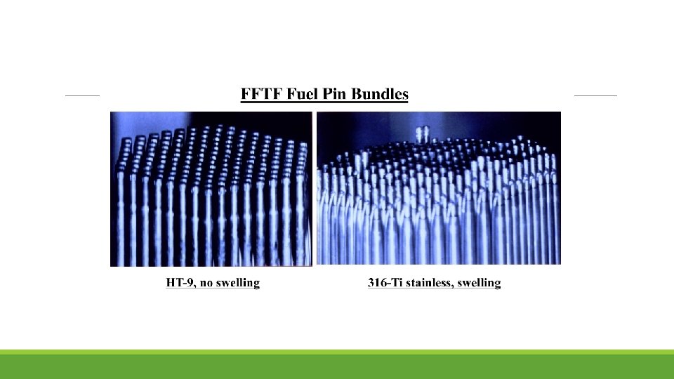
Post Irradiation Testing Nuclear reactor core structural material and nuclear fuels are used in a very hostile environment of high temperature, high pressure and with intense beta, gamma and neutron irradiation. Materials in a high radiation environment can undergo unique behaviors such as swelling and non-thermal creep. Post Irradiation Examination (PIE) is the study of used nuclear materials such as nuclear fuel. information is gained which enables the users of fuel to assure themselves of its quality and it also assists in the development of new fuels. After major accidents the core (or what is left of it) is normally subject to PIE in order to find out what happened.
PIE Technique Full range of non-destructive and destructive PIE techniques including: § Visual inspection § Puncturing and fission gas analysis § Profilometry measurements § Eddy current testing § Eddy current oxide measurement. § Gamma scanning § Light optic and scanning electron microscopy § Wavelength dispersive element analysis § ICP-MS
Case Study 1: 55 GWd/t High Burnup Fuel of PWR in Japanese PWR utilities are planning to increase the burnup of fuel from 48 GWd/t to 55 GWd/t In order to confirm the integrity of the fuel prior to the practical use of 55 GWd/t fuel, the present PIE was conducted at the fuel hot laboratory using 55 GWd/t fuel rods which had been spent for four cycles at a PWR plant in Japan. The average burnup of a fuel assembly was 52 GWd/t and 13 fuel rods were removed from the assembly for their transportation to a hot laboratory. The assembly was the 17 x 17 type with advanced fuel materials
That is three types of the claddings: 1. Zircaloy-4 claddings, which are currently in use, 2. MDA and 3. ZIRLO as improved corrosion-resistant claddings three types of fuel pellets : 1. pellets currently in use, 2. large grain-size pellets aimed at reducing the released amount of FP gas and 3. pellets with added Gd 2 O 3 at a loading of 10 wt%
(1) γ Scanning Measurement The γ scanning measurement was conducted to confirm the burnup along the axial direction of the fuel rods and the migration of FP. The observed γ ray intensity showed an almost flat pattern except at the grid section and the upper and lower ends, confirming almost even burning along the axial direction. Measurement results of the γ ray intensity of Cs-137 along the axial direction.
(2) Measurement of Dimensions Figure shows the measurement results of the fuel rod length. The rod length changes was smaller with the improved corrosion-resistant claddings (MDA/ZIRLO) than current Zircaloy-4 claddings, presumably because of the different alloy constituents of these claddings. Meanwhile, the fuel rods containing large grain-size pellets showed a larger rod length changes, presumably because of the influence of PCMI.
(3) Measurement of FP Gas Release Rate The puncture test was conducted to check the released amount of FP gas. While the FP gas release rate increased with increased burnup, the measurement results this time were lower than the overseas data due to its low linear heat rate/low temperature irradiation condition. The difference in the grain-size of pellets did not significantly affect the FP gas release rate. Comparison of fission gas release among the fuel pellet types
(4) Cladding Oxide Film Thickness and Hydrogen Content The oxide film thickness on the outer surface of the cladding was measured by the eddy current method to check any positive effect of the improved corrosion-resistant claddings. Figure shows the measurement results for the peak oxide film thickness and the corresponding data of an earlier study. The results indicate a better corrosionresistance performance of the improved corrosion-resistant claddings than current Zircaloy-4 claddings.
(5) Cladding Mechanical Properties The tensile test by using the dog-bone shape specimen was conducted at 385°C to identify the mechanical properties. Figures shows 0. 2% yield strength and fracture elongation along with corresponding data of an earlier study. The results indicate that this study claddings have good mechanical properties perfomance in the high burnup region. The mechanical properties data of the improved corrosionresistant claddings fall within the existing data range for the claddings currently in use.
Case Study 2 -Underwater Fuel Inspection for Irradiated LWR Fuels in KAERI Table shows the in-pool examination activities conducted in PIEF for underwater inspection of spent nuclear fuels at KAERI.
Visual Inspection A radiation resistant underwater camera mounted on the XY table is used for the visual inspection of the fuel assembly. Fuel assembly standing on rotary base plate of the visual and dimensional inspection stand is inspected as the rotary plate rotates the fuel assembly to expose all faces to a camera. The measuring head equipped with underwater cameras and detecting sensors is raised and lowered along the fuel assembly for inspection. Visual and Dimensional Inspection Stand in PIEF Pool of KAERI
Hold-down Spring Force Measurement The spring should have enough strength to suppress the fuel assembly and should not exceed the design strength during irradiation so as not to make any deflection or damage of the fuel assembly structures due to thermal and irradiation growth of the assembly. The leaf spring of fuel assembly is pressed down and the load -displacement curve is obtained which reveals the spring characteristics after irradiation.
Exponential experiment The experiment was applied to the sub-criticality estimation for LWR spent fuel and confirmed that the experiment can be used to obtain the neutron effective multiplication factor for the subcritical system in order to validate criticality calculations. The exponential experiment system is installed in PIEF pool at KAERI in order to determine the neutron multiplication factor for the PWR spent fuel stored in pool.
In-Pile Measurements Fuel Temperature Heat transfer (fuel thermal conductivity, gap conductance) Rod Internal Pressure Change Fission gas release, fuel densification & swelling Fuel Stack Length Change Fuel Cladding Length Change Fuel densification & swelling PCMI, (or when no PCMI, surface heat transfer, growth) PCMI, (or when no PCMI, creep & growth, corrosion) Fuel Rod Outer Diameter Change
Summary Performance of materials in critical components of the nuclear reactor need to be assessed for assurance of safe continued operation of Nuclear Power Plants. Today’s nuclear power stations have proven the fuel to be very reliable in its performance, with a negligibly small rate of failure. Reliable predictions of fuel behaviour are important in order to achieve improved design and economics of the nuclear fuel cycle. Feedback information generated by post irradiation examination is used by designers, fabricators, reactor operators in improving design, safety & economy of the nuclear plant systems.