NUCLEAR REACTOR MATERIALS 2 MATERIALS IN BWR In

NUCLEAR REACTOR MATERIALS 2. MATERIALS IN BWR

In this Chapter 1. Design and Materials of BWR Components 2. Corrosion-Related Issues in BWR

BWR and PWR

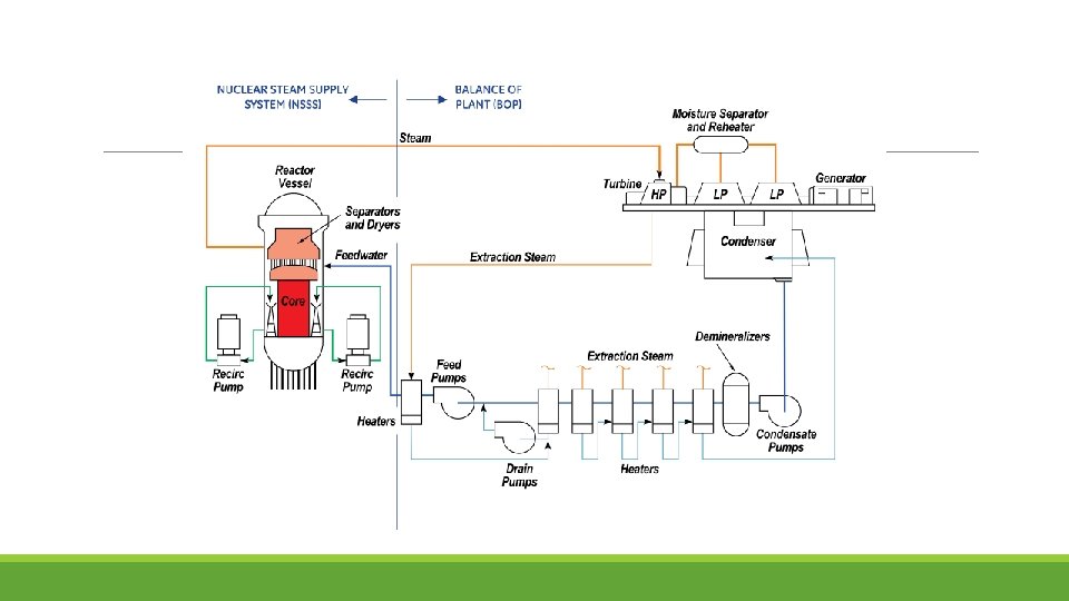
Principle of Steam Generation

Major Components

At the top of the core there is a dome or upper plenum at the top of which are steam separators, then steam dryers. The separators produce a rotating vortex flow, and the liquid water is centrifugally forced to the outside, where it is routed outside the separator and falls on the top of the dome, then into the annulus. This 288 °C water is cooled by the ≈200°C feed water to 274°C. Thus, most structural materials (the vessel, the external piping, the outside of the shroud, the bottom plenum and the core support plate, etc. ) are exposed to 274°C water.

BWR fuel rods are enclosed in “channels” or zirconium alloy wrappers around the fuel bundle (BWR fuel is comprised of an array of fuel rod. About 90% of the water flows through the fuel channel, and 10% flows in the “bypass” regions between fuel bundles or around the periphery of the core along the inside of the shroud.

1. Design and Materials of BWR Components
 water chemistry is necessarily of high purity because boiling occurs")
Boiling water reactor (BWR) water chemistry is necessarily of high purity because boiling occurs on the fuel rods and the resulting steam directly drives the turbine. If high purity were not maintained then high concentrations of aggressive species would be formed on the heat transfer sur-face where boiling occurs. While the condensate from the turbine is fully demineralized before returning to the reactor pressure vessel as feed water, the reactor water must also be cleaned up, because otherwise nonvolatile impurities would concentrate because of boiling. The reactor water clean up system typically runs at 0. 5 to 1% of the feed water flow rate, cooling the water before running it through demineralizers.

Reactor Pressure Vessel
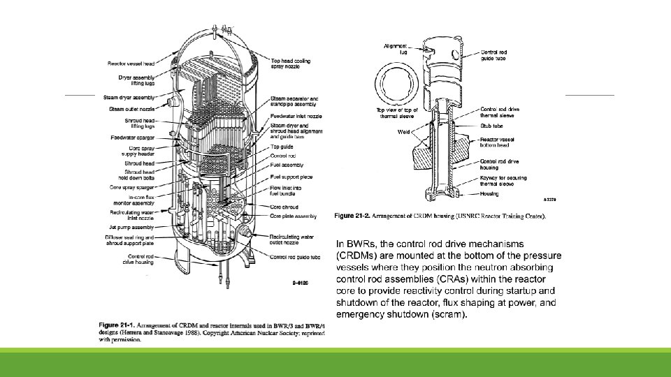

Reactor Internals

Recirculation Piping

Jet Pump

Lower Plenum

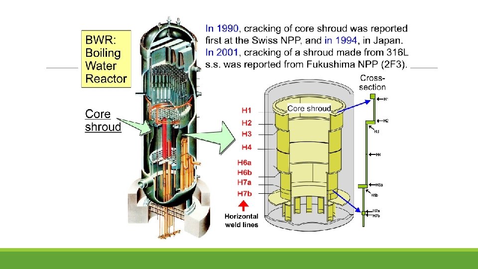
Core Shroud

Steam Separator

Steam Dryer

2. Corrosion-Related Issues in BWR

Water Chemistry As water flows through the core and is exposed to ionizing radiation (esp. neutrons, which are slowed by their collisions with water and eventually reach “thermal” energies, a wide variety of radiolysis products are produced. The primary species can be considered to be H 2 and H 2 O 2. H 2 partitions to the steam phase, so the recirculated water is always oxidant rich. H 2 O 2 decomposes to H 2 O and O 2 , and the relative proportions of O 2 and H 2 O 2 changes with time and distance away from the core. In the core, some 16 O is transmuted to 16 N, which has a half-life of 7. 13 seconds. In “normal water chemistry, ” the stable form of N is NO 3 – , which remains soluble. However, when sufficiently high H 2 is injected into BWRs, the stable form becomes NH 3, which are volatile. Thus, rather than remaining in the recirculated reactor water as it decays, 16 N becomes volatile and can cause a large increase (up to ( 10 X) in the turbine radiation level.

The presence of oxidants like H 2 O 2 and O 2 in the water cause an increase in the corrosion potential of metals Relationship between corrosion potential of 304 SS and dissolved oxygen content as a function of water temperature

ECP Monitoring Locations

SCC in Piping
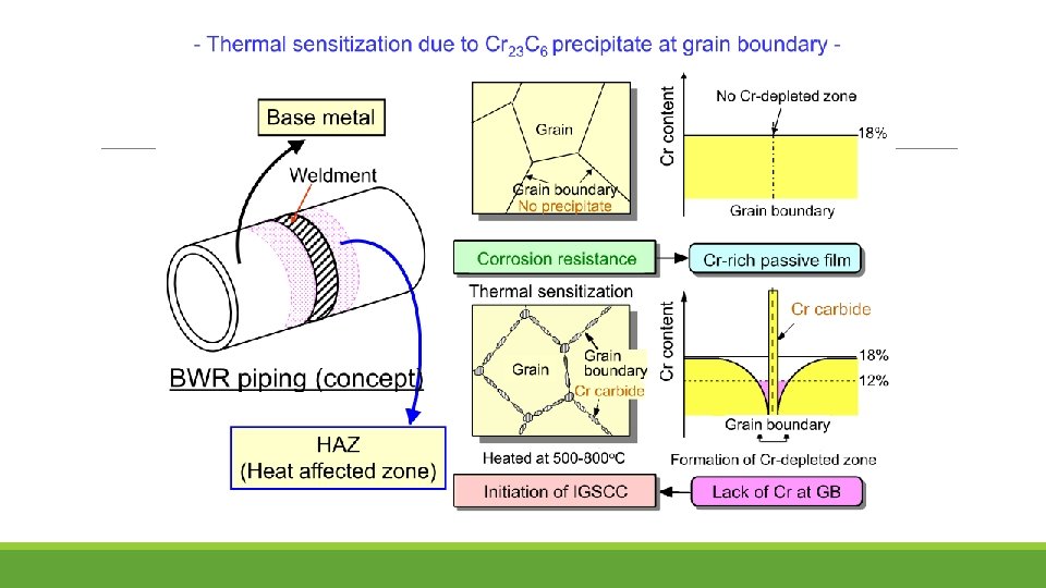
 frequently occurred in BWR plants in the heat-affected zone of")
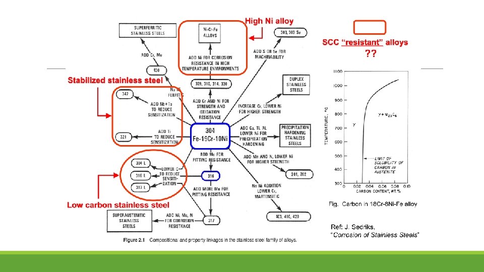
Stress corrosion cracking (SCC) frequently occurred in BWR plants in the heat-affected zone of the welds in PLR piping fabricated from type 304 SS. The adoption of low-carbon SS was considered to be the one of the solutions to SCC, as such 316 L has been developed. Typically, the shrouds made from type 304 SS have been progressively replaced with those made from type 316 L SS

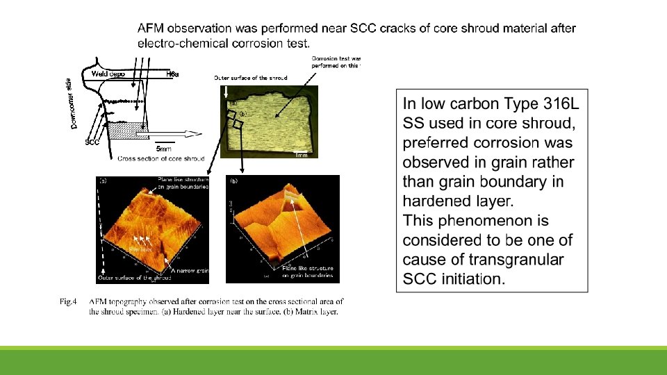
SCC in Core Shroud A core shroud is a stainless steel cylinder surrounding a nuclear reactor core whose main function is to support core and direct the cooling water flow inside of the reactor pressure vessel The core shroud is composed of multiple cylindrical thermal shields stacked on top of each other. In between each thermal shield is a horizontal, stainless steel cylindrical plate that helps keep thermal shields in place. The plates are then welded together with thermal shields so that they create one solid structure. Vertical tie bolts are then used to reinforce each horizontal plate with their adjacent thermal shields, stabilizing the cylindrical core shroud. The cracks on the shroud surface were mainly verified near the shroud ring weld line and core region weld line. The crack shape could be classified into two types: one type was circumferential cracking in the shroud ring, and the other was isolated occurrences of radial cracking in the core region.

Inspection of Shroud
 has been developed for obtaining in situ samples (boat shaped)")
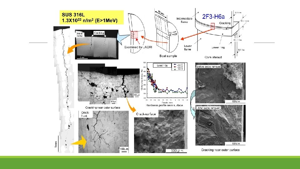
Boat Sampling Technique (BST) has been developed for obtaining in situ samples (boat shaped) from the core shroud of BWR for determination of sensitization level of HAZ of the material by metallurgical analysis. The BST incorporates mainly Sampling Module, mechanical, pneumatic and electrical subsystems. This technique can be used, remotely and under water, to obtain samples from a desired location, from the core shroud of BWRs. The weight of boat sample would be 4 grams and the time required for obtaining each sample would be 90 minutes. Boat Sample (42 mm x 26 mm x 3 mm)

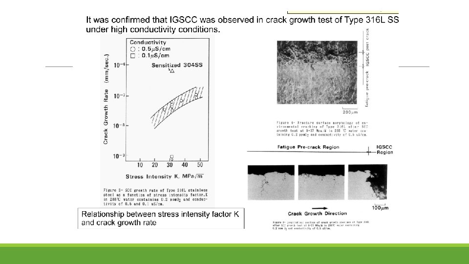
SEM observations indicate the mechanism common to low-carbon stainless steel SCC of the initiation of cracking occurring in a hardened layer of the surface as TGSCC, and TGSCC subsequently changing into IGSCC.
 TGSCC is initiated at surface where severe plastic deformation is introduced")
Transgranular SCC (TGSCC) TGSCC is initiated at surface where severe plastic deformation is introduced by surface machining and then shifted to IGSCC. For TGSCC, most cracks were initiated at an angle of 60° against load direction. It can deduce that slip deformation is one of main factors for TGSCC.

Solution One method used to fix the core shroud crack is reinforcing the core shroud plates. This is done using an anchor bolt, which is used to attach additional steel plates to the core shroud surface, thereby reinforcing the structure. This is the most common method used to fix cracks in the core shroud since it is easy and relatively safe. Replacement of the core shroud is also an option, but it is not recommended because the cracked plates must be removed manually, leaving the laborers susceptible to radiation.

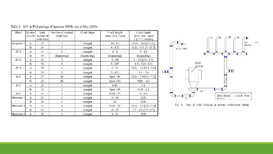
Primary loop Recirculation PIPING. The Recirculation System is used in the Boiling Water Reactor design. This system provides the following functions: 1. Control of reactor power level through the variable speed recirculation pumps 2. Cooling of the reactor during off-normal modes 3. Paths for emergency makeup and chemical purification

Several penetrations come off the recirculation loop, including: ◦ the reactor water cleanup system used to purify the reactor coolant, ◦ the shutdown cooling system, used to cool the reactor below 350 F Penetrations providing water to the recirculation system include: ◦ low pressure coolant injection to provide emergency makeup to cool the reactor at low pressure and high flowrate (~2000 -3000 gpm), ◦ shutdown cooling system to return cooled water back to the reactor, ◦ isolation condenser, if used, to return cooled water back to the reactor. The isolation condenser is used to cool steam from the reactor if the main steam isolation valves close. The water is returned to the reactor by natural circulation. Pumped flow is not required.
")
SCC IN PLR PIPING Existing BWR nuclear power plants Primary Loop Recirculation Pipings (PLR) have large and many welded seams, because the conventional PLR have been mainly constructed by welding of straight pipes and standard fittings such as elbows, crosses, tees, reducers, and nozzles. The piping is made up of low-carbon stainless steel (SUS 316 LC) as it was thought that SCC generated by sensitization would be prevented by using low-carbon material. However, the results of later mock-up tests and experiments confirmed that hardened surfaces increased susceptibility to TGSCC, which progressed to IGSCC in crack growth.

Case Study Many cracks in PLR piping were found during March 2003 in several plants. The welds in the PLR piping were inspected by an ultrasonic test from the external surface. Cracks were found near the welds inside the piping. This cracking was distributed throughout the whole of the recirculation piping and there was no specific pattern

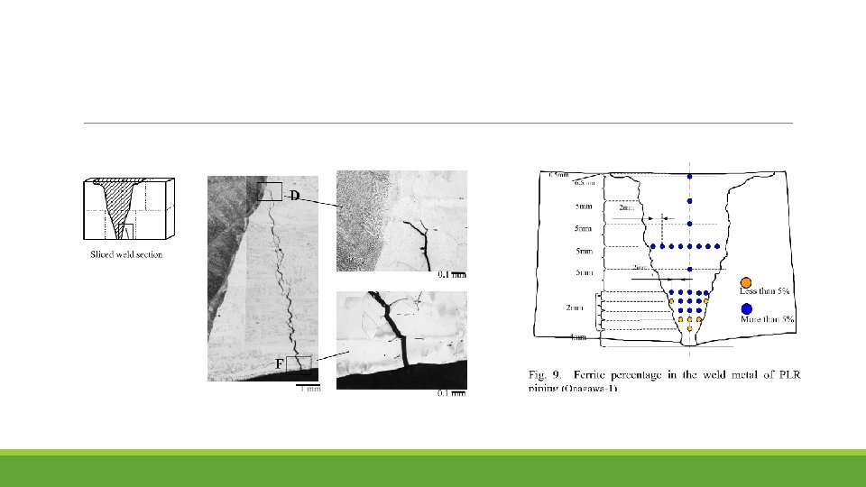
Analysis The thickness of the hardened layer was found to be 20µm on the inner surface of the PLR piping. It was found that TGSCC had been initiated from this surface layer and propagated to the inside of the pipe material by IGSCC. In some cases, the crack had penetrated the welding metal itself. The deteriorated layer also formed on the inner surface of the pipe joints that had been machine-finished during the manufacturing process. It was found that the amount of ferrite had decreased to 5% or less in the boundary part of the weld metal due to the dilution of ferrite between the pipe materials, which hardly included any ferrite, and the weld metal, which contained a large amount of ferrite. This resulted in the shortage of ferrite in the weld metal. No obvious sensitization at the grain boundaries was apparent, and the shape of most of the cracks also depended on the local residual stress distribution on the surface

Repair/ Maintenance Techniques for SCC in PLR Piping Repair methods and preventive maintenance techniques related to material improvement and residual stress relaxation for SCC in PLR piping. § Corrosion Resistant Cladding § Internal Polishing § Induction Heating Stress Improvement § Solution Heat Treatment § Heat Sink Welding § Weld Overlay

Corrosion Resistant Cladding The CRC method is used to reduce SCC susceptibility by cladding the wetted inner-surface of sensitized portions near the welded joints of piping with non-sensitized deposited metal (Fig. 1). There are various methods to clad the wetted part inside the piping with deposited metal (inside weld overlays) and the method typically used is shown in Fig. 2.

The SCC susceptibility is reduced by securing high ferrite content on the wetted inner-surface of the piping’s welded joints. It is shown that generally in the low-carbon zone, no SCC is observed in the area where ferrite content is over about 5% SCC Susceptibility vs. Ferrite Content

Internal Polishing To relieve residual stress of the innersurfaces of piping, top surface stress is shifted to compressed sides by polishing the inside surface. This reduction in residual stress results in the suppression of SCC generation. Relief of Residual Stress on Surfaces by Polishing and its Effect on SCC Suppression
 To generate the same temperature difference found at the")
Induction Heating Stress Improvement (IHSI) To generate the same temperature difference found at the heat effective zone that goes through the thickness of the pipe, the outer-surface is heated by the high-frequency induction heating method and the inner-surface is simultaneously cooled by water. The thermal stress generated by this process relieves the inner-surface residual stress of the piping.
 Chromium rich carbide precipitation from the grain boundary is decomposed")
Solution Heat Treatment (SHT) Chromium rich carbide precipitation from the grain boundary is decomposed when heated by high temperature ( over 1000℃ ) and dissolves uniformly into the base material, which causes the chromium-depleted-layer around the grain boundary to disappear. This heating method, called solution heat treatment (SHT), can eliminate sensitized areas in the material formed by welding and reduces residual stress at the same time A furnace is needed for this method and it is recommended that it is applied to welded joints at factories.
 HSW is a method which the inside of pipes are")
Heat Sink Welding (HSW) HSW is a method which the inside of pipes are welded while cooled by flowing water or sprays after partitions are formed by the in gas welding for up to two or three layers. Using this method, thermal stress is generated by the temperature difference of the outside and inside of piping that goes through the thickness of the material. This thermal stress reduces tensile residual stress, which is the cause of SCC around the inside surface of the welded pipes.

Weld Overlay In weld overlays, high ferrite welded metal that is superior in SCC resistance is overlaid in a belt around the outside of welded joints in piping with SCC. Strength was secured in the belt-shaped overlay welded part of the piping, thus covering up for lost strength in the part of the piping where the crack occurred

Low Carbon SS

It was confirmed that SCC growth rate highly increased with increase of cold work in Type 316 NG SS.

IASCC of In-Core Materials
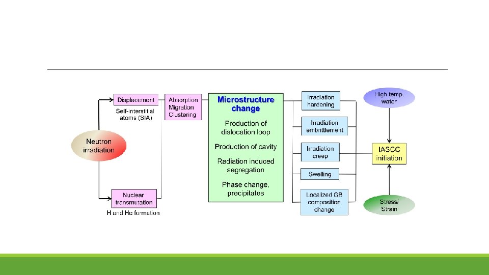
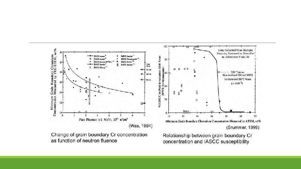
 RIS chromium depletion (2)")
Mechanism of IASCC Existing theories fall into five categories: (1) RIS chromium depletion (2) Irradiation hardening (3) Localized deformation (4) Selective internal oxidation (5) Irradiation creep
 RIS chromium depletion")
(1) RIS chromium depletion
 Irradiation hardening")
(2) Irradiation hardening
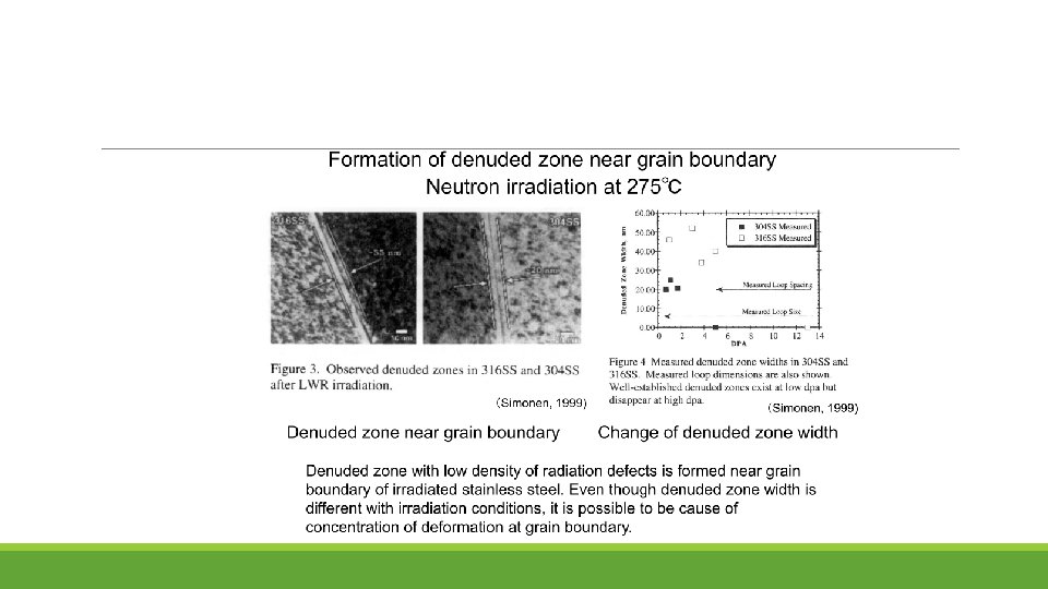
 Localized deformation")
(3) Localized deformation
 Selective internal oxidation")
(4) Selective internal oxidation

Summary for SCC Mitigation

SCC Mitigation by Water Purity Control

SCC Mitigation by Water Purity Control Earlier, many BWRs operated at solution conductivities between 0. 3 and 0. 8 S/cm, which corresponds to 30 – 90 ppb of impurities, which are particularly damaging and were responsible for extensive cracking By the early 1990 s, the average conductivity had decreased to 0. 13 S/cm, and it is currently 0. 11 S/cm, with much of the residual conductivity (theoretical purity water is 0. 055 S/cm) related to chromate and Zn ion Chloride and sulfate have the largest effect on stress corrosion cracking; some ions, like chromate, nitrate and silicate anions have little effect on SCC unless their concentrations exceed 25 ppb, 100 ppb or 1000 ppb respectively

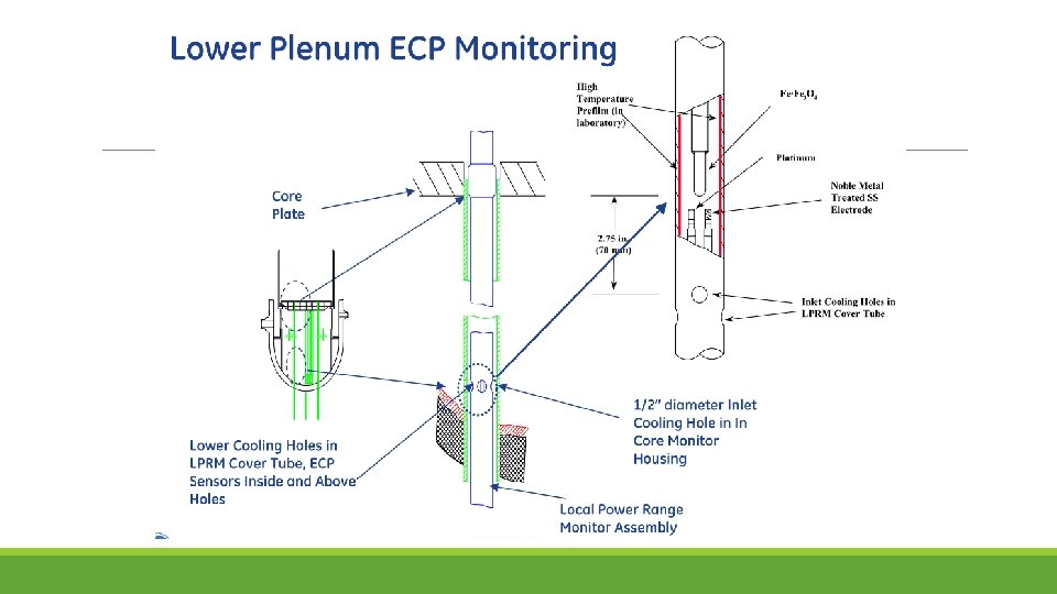
ECP Monitoring Locations

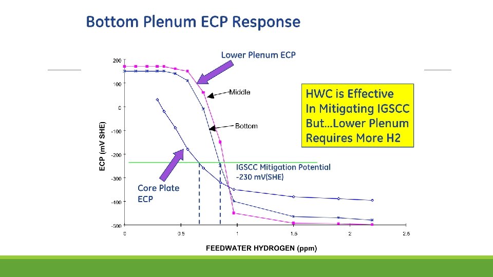
SCC Mitigation by Hydrogen Water Chemistry The most effective way to mitigate SCC in BWRs is to modify the water chemistry by reducing the corrosion potential. Hydrogen Water Chemistry (HWC) does this by injecting H 2 into the feed water. H 2 levels above ≈500 ppb effectively suppresses radiolysis PWRs use ≈3 ppm H 2, but such levels are not economically achievable in BWRs, the feed water in BWR would need to have more H 2. Why? “protection potential” of -230 m. V she Relation between corrosion potential and injected feedwater hydrogen content observed in feedwater line at a specific BWR.

The decrease in corrosion potential occurs not by suppressing radiolysis but by gamma-radiation enhanced recombination in the annulus. The gamma level in the downcomer varies with reactor design, and some wide annulus plants have insufficient gamma radiation at the outside of the annulus to produce very effective recombination. In the best plants, HWC drops the oxidant levels from ≈200 ppb to < 1 -2 ppb at the bottom of the annulus, which feeds the recirculation piping.

Attempts to improve the coverage of HWC considered the obvious option of increasing the H 2 to higher levels. In many plants, this produces an adequately low corrosion potential in the bottom plenum and perhaps along the inside of the shroud. At such high H 2 levels, all plants see a large increase in “turbine shine” ( 16 N in the steam). However, once boiling occurs (essentially no boiling occurs in the bypass water outside of the fuel bundles), the H 2 level in the water drops significantly. Thus, components exposed to this water remain at high corrosion potential and remain unprotected from stress corrosion cracking

Regions of the pressure vessel internals and recirculation piping protected by hydrogen water chemistry.

Chemistry of Radioactive Nitrogen-16 is the most dominant radioisotope which causes gammaradiation from the primary system of BWR under plant operation. A number of radioactive nitrogen species are evolved from chemical reactions among radiolytic species of water and nitrogen species. Among nitrogen species, chemically stable compounds, such as nitrogen molecule (N 2), nitric oxide (NO), and ammonia (NH 3), are released into the main steam line and determine the gamma-radiation level in the turbine building.

Numerical model calculations and plant experience related to chemical behaviors of radioactive nitrogen (13 -N and 16 -N) in BWR primary systems have suggested the following: i. Calculated results suggest that the major radioactive nitrogen species released to the vapor phase was nitrogen mono-oxide. ii. Based on 13 N measurement in the main steam of a BWR, 85% of 13 N was found to be anion. iii. Chemical behaviors of 13 N and 16 N from calculations were not the same because of the difference in half-lives of 13 N and 16 N. iv. Since the half-life of 16 N is short, the main source of 16 N was the boiling channels in the reactor core and 13 N was easily accumulated in the core by-pass channels where the residence time was several times longer than in fuel channels.

Increase in dose rate in main steam lines of commercial BWRs under HWC Chemical behavior of 16 -N in the BWR primary system is rarely quantified because it decays rapidly with a half-life of 7. 13 s, so that 13 N (half-life: 9. 97 min) is measured as the representative of radioactive nitrogen in the BWR primary system.

SCC Mitigation by Noble. Chem

HWC vs. Noble. Chem TM Technology

ECP Reduction With Noble. Chem

Noble. Chem was developed by GE in which all wetted surfaces could be made catalytic. Metals such as Pt, Pd, Rh, Ru, Os and Ir are electro-catalytic; i. e. , reactions (esp. H 2 and O 2 or H 2 O 2 reactions) are dramatically accelerated. Pt can be added through: ◦ can be added to alloys and used in thermal spray powders ◦ introduce low concentrations of Pt salts (e. g. , Na 2 Pt(OH) 6 ) into BWR water, which results in Pt depositing on the surfaces of all wetted parts. Pt concentrations below 1% of a monolayer are adequate. An “On. Line Noble. Chem” is being developed that introduces Pt during full-power operation.

Electrocatalytic processes are developed for improving the efficiency of the oxygen/ hydrogen recombination process and thereby extending the region of protection to the reactor core region Advantage of Noble. Chem: Under the Noblechem process protection of the core internals from stress corrosion cracking can be achieved at lower feedwater hydrogen concentrations that do not give rise to accelerated 16 N offgas rates and increases in the main steam line radiation
 Stoichiometry of H 2 and O 2 To achieve")
Effectiveness of Noble. Chem 1) Stoichiometry of H 2 and O 2 To achieve low corrosion potential at all locations of interest, H 2 must be in stoichiometric excess. Considering only O 2, there must be two moles of H 2 per mole of O 2. This is easily achieved at fairly low levels of H 2 injection to the feed water at all locations until boiling occurs. Thus, areas above the fuel channel are not protected. Additionally, there may be areas in the upper regions of the annulus where the (H 2 -rich) feed water does not adequately mix with the core water, and stoichiometric excess H 2 might not exist in some local regions.
 Limitation of Materials Low corrosion potential does not guarantee total mitigation of SCC.")
2) Limitation of Materials Low corrosion potential does not guarantee total mitigation of SCC. Higher yield strength materials, such as alloy 182/82 weld metal, irradiated stainless steel, cold worked stainless steel or alloy 600, benefit less than sensitized stainless steel, because cold work causes higher growth rates at both low and high corrosion potential
 Development of crack If cracks grow extensive in between Noble. Chem applications, O")
3) Development of crack If cracks grow extensive in between Noble. Chem applications, O 2 can get to areas of the crack flank that are not catalytic, so no catalytic benefit is observed. This is a well-understood limitation, and where it has occurred in the operational reactors, it has been associated with a digression from operational procedure and the inadequate control of the hydrogen feed rate.

Removal of Surface Cold Working Relationship between SCC Crack Depth and Surface Hardness.

If the surface of stainless steel is machined, fine grains with a diameter of 0. 5 μm or less form in the surface-most region due to recrystallization induced by the machining. A further cold-worked layer forms beneath this due to slip deformation, also caused by the machining. It has been identified that these microstructural changes play a significant role in non-sensitized SCC To eliminate this surface cold-worked layer as a cause of SCC, the flap wheel and CNS (clean ’n strip) polishing techniques have been used on the reactor shroud and other components for recent plants.
 to analyze the structure of SUS 316 L that")
EBSD (electron back scattering diffraction) to analyze the structure of SUS 316 L that has been subject to various types of surface finishing. The black regions indicate the cold-worked layer.

Material Improvement It is believed that grain boundary separation can progress easily at grain boundaries where the orientation of the adjacent crystals is not aligned (random grain boundaries). Grain-boundary-character-controlled materials are materials in which the microstructure is controlled to increase the proportion of matched grain boundaries at which the adjacent crystals are oriented in a particular way. It is anticipated that this will improve SCC resistance by isolating regions of joined-up random grain boundaries.

Evaluation of SCC Resistance of Grainboundary-character-controlled Material The results show that, compared to the non-controlled material, the SCC crack length is much shorter for the controlled material. Also, for both materials, the number of cracks is much lower at matched grain boundaries and therefore the initiation and growth of SCC is inhibited in the grain-boundary-character-controlled material in which the proportion of matched grain boundaries has been increased.
- Slides: 91