
Nuclear Division Mild Environment Qualification and Maintenance Marie





- Slides: 25
Nuclear Division Mild Environment Qualification and Maintenance Marie Nemier, Seismic & EQ Manager - Qual. Tech NP
Mild Environment Qualification and Maintenance § Outline – Definition – Significant aging mechanisms – Example: Relay life extension program of naturally aged relays – Open Part 21 of relay – Importance of preventative maintenance / surveillance – Any actions required by SC-2
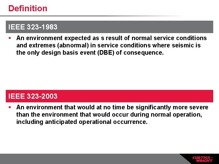
Definition IEEE 323 -1983 § An environment expected as s result of normal service conditions and extremes (abnormal) in service conditions where seismic is the only design basis event (DBE) of consequence. IEEE 323 -2003 § An environment that would at no time be significantly more severe than the environment that would occur during normal operation, including anticipated operational occurrence.
Definition (2) SIGNIFICANT AGING MECHANISM DEFINITION § An aging mechanism that, under normal and abnormal service conditions, causes degradation of equipment that progressively and appreciably renders the equipment vulnerable to failure to perform its safety function(s) during the design basis conditions.
Significant aging mechanism examples § § § Pressure Radiation Operational cycles Temperature Humidity Non-seismic vibration
Significant aging mechanism examples (2) § Normal state (i. e. , Energized or De. Energized) § In–cabinet heat rise § In-cabinet air circulation § Proximity to other components
Relay Life Extension Test Program • Received over 100 relays from utility that were removed from service • Many relays were original equipment installed (~40 yrs old) • Based number to test on the EPRI sampling plan
Relay Life Extension Test Program (2) • Types of relays: • Auxiliary • Control • Time Delay • Protective Over-voltage • Protective Over-current • Protective Differential • Lock-out
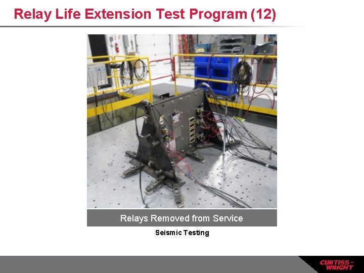
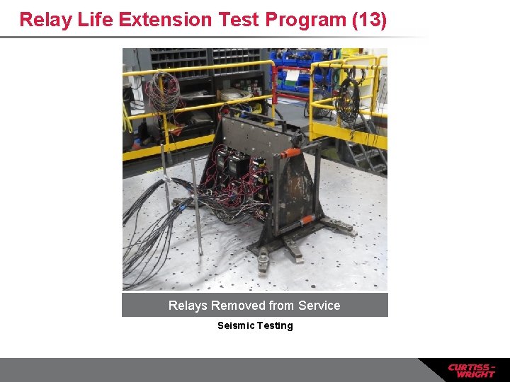
Relay Life Extension Test Program (3) • Program consisted of the following tasks: • Initial receipt inspection for any signs of deterioration • Functional test • Operational cycling -100 cycles at rated load • Functional test • Seismic test • Final functional test • Evaluation
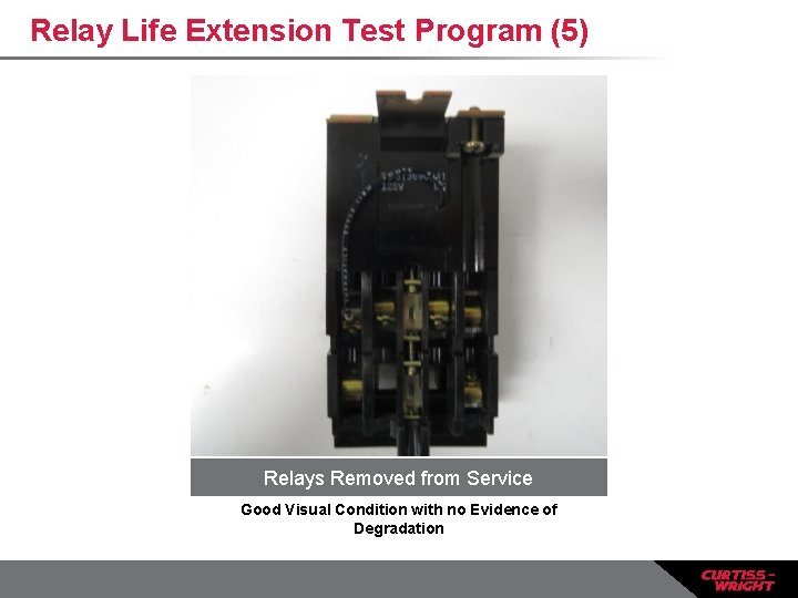
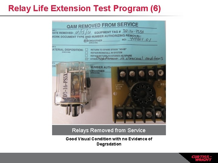
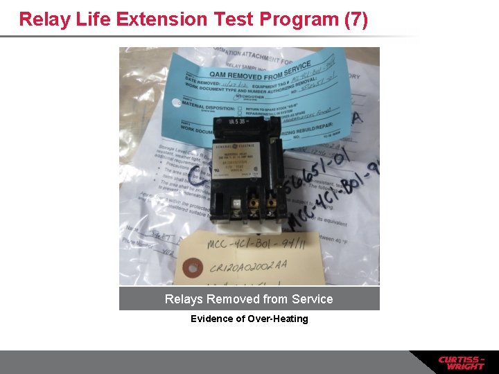
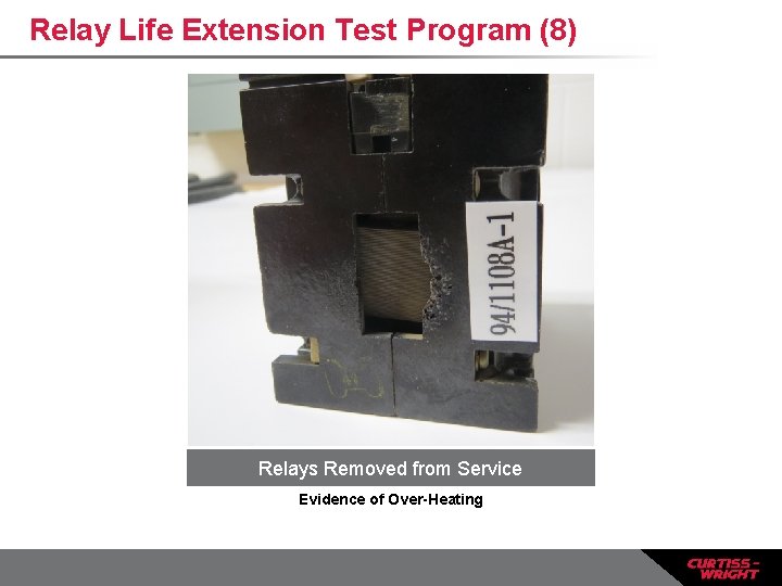
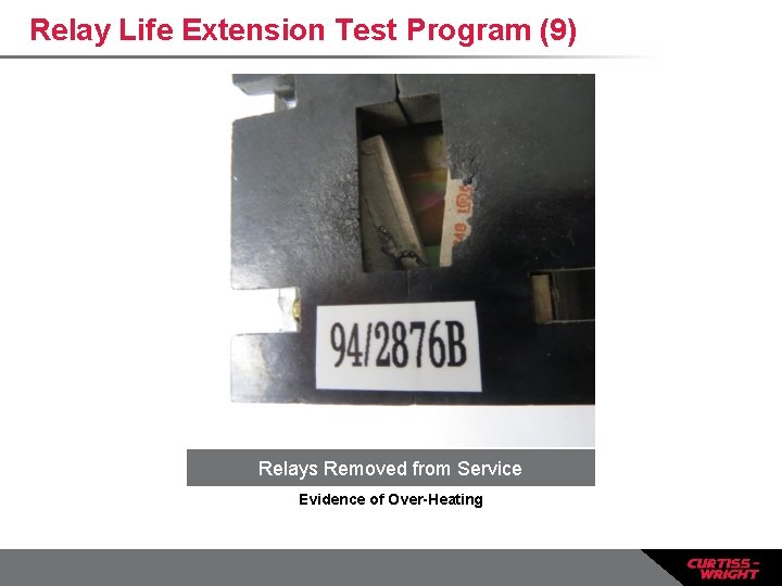
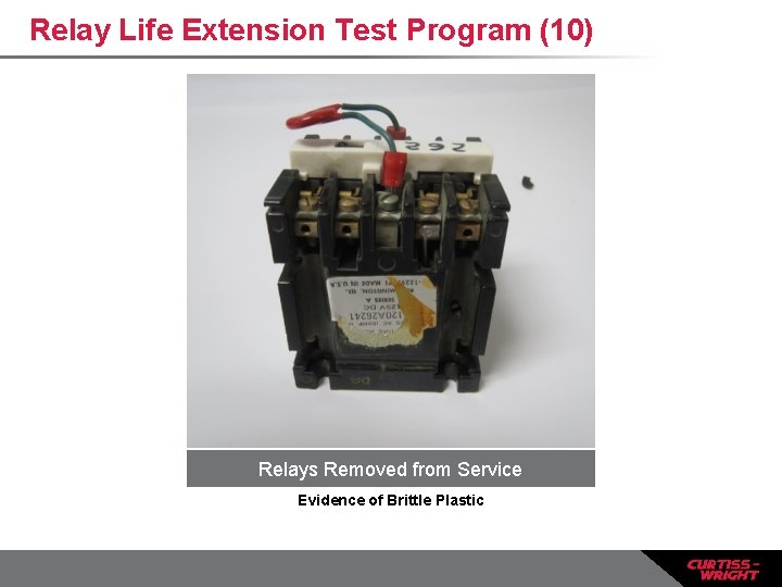
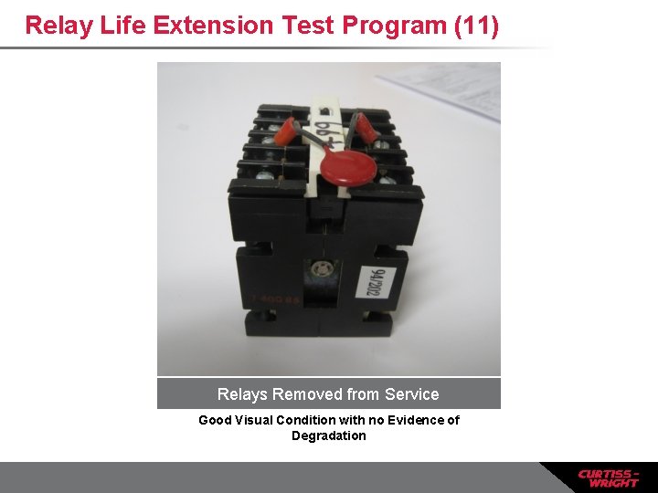
Relay Life Extension Test Program (4) • Relays were received with a great variability in condition • Most relays showed no signs of significant wear, degradation or damage • Common discovery – high contact resistance • Some relays were found with evidence of overheating • Charred case • Cracked solder • Brittle case
Relay Life Extension Test Program (5) Relays Removed from Service Good Visual Condition with no Evidence of Degradation
Relay Life Extension Test Program (6) Relays Removed from Service Good Visual Condition with no Evidence of Degradation
Relay Life Extension Test Program (7) Relays Removed from Service Evidence of Over-Heating
Relay Life Extension Test Program (8) Relays Removed from Service Evidence of Over-Heating
Relay Life Extension Test Program (9) Relays Removed from Service Evidence of Over-Heating
Relay Life Extension Test Program (10) Relays Removed from Service Evidence of Brittle Plastic
Relay Life Extension Test Program (11) Relays Removed from Service Good Visual Condition with no Evidence of Degradation
Relay Life Extension Test Program (12) Relays Removed from Service Seismic Testing
Relay Life Extension Test Program (13) Relays Removed from Service Seismic Testing
Relay Life Extension Test Program (13) § Conclusions § Failures were not identified during preventative maintenance / surveillance § Significant aging mechanisms (in-cabinet heat rise and proximity to other components) impacted mild environment seismic qualification and the ability of the relay to perform its safety function during a DBE § The failures were not common mode – relays without significant aging mechanisms performed to original qualification levels or higher
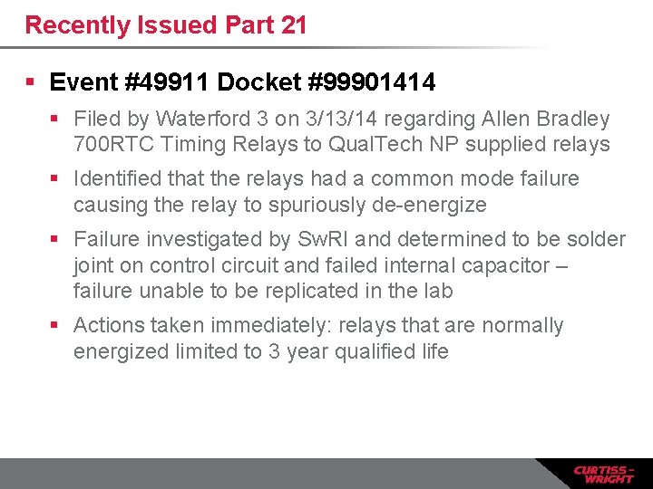
Recently Issued Part 21 § Event #49911 Docket #99901414 § Filed by Waterford 3 on 3/13/14 regarding Allen Bradley 700 RTC Timing Relays to Qual. Tech NP supplied relays § Identified that the relays had a common mode failure causing the relay to spuriously de-energize § Failure investigated by Sw. RI and determined to be solder joint on control circuit and failed internal capacitor – failure unable to be replicated in the lab § Actions taken immediately: relays that are normally energized limited to 3 year qualified life
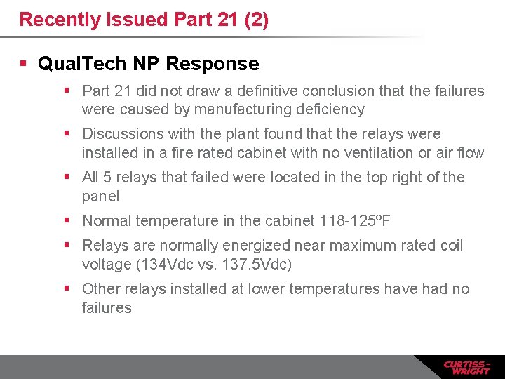
Recently Issued Part 21 (2) § Qual. Tech NP Response § Part 21 did not draw a definitive conclusion that the failures were caused by manufacturing deficiency § Discussions with the plant found that the relays were installed in a fire rated cabinet with no ventilation or air flow § All 5 relays that failed were located in the top right of the panel § Normal temperature in the cabinet 118 -125ºF § Relays are normally energized near maximum rated coil voltage (134 Vdc vs. 137. 5 Vdc) § Other relays installed at lower temperatures have had no failures
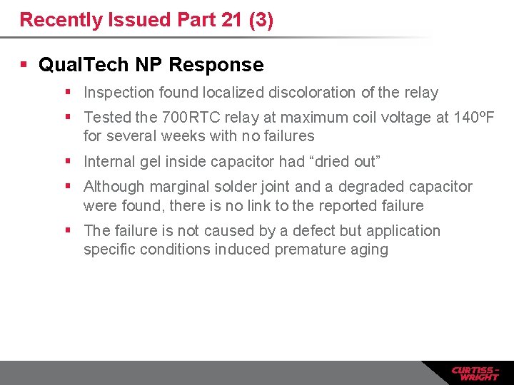
Recently Issued Part 21 (3) § Qual. Tech NP Response § Inspection found localized discoloration of the relay § Tested the 700 RTC relay at maximum coil voltage at 140ºF for several weeks with no failures § Internal gel inside capacitor had “dried out” § Although marginal solder joint and a degraded capacitor were found, there is no link to the reported failure § The failure is not caused by a defect but application specific conditions induced premature aging
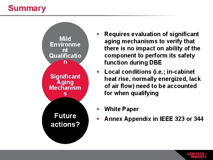
Summary Mild Environme nt Qualificatio n § Requires evaluation of significant aging mechanisms to verify that there is no impact on ability of the component to perform its safety function during DBE Significant Aging Mechanism s § Local conditions (i. e. ; in-cabinet heat rise, normally energized, lack of air flow) need to be accounted for when qualifying Future actions? § White Paper § Annex Appendix in IEEE 323 or 344
Marie Nemier 513. 528. 7900 ext. 2137 mnemier@curtisswright. co m http: //qualtechnp. cwfc. c om