NOx Control Ammonia Storage Hazardous Chemical Rules 1989


 Ø Tertiary air and kiln exhaust")
 Air containing 21% oxygen recovered from")


 SCC works by staging the introduction of fuel,")


 Basis of SNCR The SNCR process is basically the injection")
 In urea reagent based SNCR system aqueous urea solution is")
 Residence Time Increasing the residence time available for mass transfer")
 Normalized Stoichiometric Ratio (NSR) NSR is the ratio of moles")
 SNCR System Process control Combustion chamber / Boiler Reagent")

 Injector – Optimum location and design impact on operational")
 Case Study 1 : Parameters Clinker TPD Fuel Type")
 Potential Problems With SNCR Ø Not all of the")


 70")


 \"Hazardous Chemical \" means - (i)any chemical which satisfies")
 \"industrial activity\" means- i. an operation or process carried out in")
 \"Threshold quantity\" means, - (i) in the case of a hazardous")
 \"Threshold quantity\" means, - (ii) in the case of a hazardous")
 these rules")
 and 3) S. No Authority (ies) with legal backing")
 and 3) S. No Authority (ies) with legal backing")
 and 3) S. No Authority (ies) with legal backing")
 and 3) S. No Authority (ies) with legal backing")


- Slides: 58
NOx Control, Ammonia Storage & Hazardous Chemical Rules 1989 as amended to date By Anil Jain Shree Cement Limited CSE, New Delhi 21. 12. 2017
Emissions from Cement Plant Fugitive emission Boiler PM Cement mill & Packing Kiln Mining Grinding Fugitive emission PM NOXS O 2 Cooler PM
Environmental Effects of SO 2 and NOx Smog • Sulphate aerosols • Ozone, PAN SO 2+ H 2 O H 2 SO 3 NOx+H 2 O HNO 2, HNO 3 Acid Rain
Emission Standards for Cement Plants Notified on 25 th. Aug, 2014 and amendment dt 9 th. May 2016, Effective-1 st April, 2017
NOx Formation in Cement Process
NOx Formation in Cement Process Ø Kiln combustion zone is the primary source of thermal NOx due to temperatures well above 1, 400 °C. Nitrogen in combustion air is oxidized to NOx (thermal NOx) at a flame temperature of 1, 870 °C in a rotary kiln, which heats the process material to 1, 480 °C. Ø In comparison, combustion temperature in a calciner or in a kiln riser duct is well below 1, 200 °C, thereby suppressing thermal NOx formation. Ø Longer residence times at high temperatures and greater amounts of oxygen in the combustion zone will increase NOx.
Fuel NOx Formation Ø Fuel nitrogen is oxidized into NO during combustion process relatively independent of temperature "N" + O → NO Ø About 30% of fuel NOx is formed in the calciner in the absence of tertiary air and 70% is formed when tertiary air is supplied. Ø 0. 1% increase in Nitrogen content will increase NOx emission by 60 mg/Nm 3. Fuel Characteristics ILC Low NOx with high temp. SLC Pet coke- 2% N 1380 800 920 Pet coke- 1% N 780 560 640 Coal<26%VM 1130 790 830 Coal 26 -36% VM 540 500 810 Coal > 36% VM 480 430 790
Fuel Quality Characteristics % Indian Indonesia South African Pet Coke Total Moisture 10 -20 10 -30 8 5 Ash 25 -50 10 -15 15 -17 1 Volatile Matter 16 -30 25 -35 23 10 Carbon 30 -35 60 70 -80 87 Hydrogen 2 -4 4. 5 4 -5 3. 7 Nitrogen 0. 7 -1. 15 1 2 -2. 5 1. 8 Sulphur 0. 3 -0. 8 1 1 5. 5 Oxygen 4 -8 12 8 -9 1. 7 2800 -5000 5500 6500 7800 GCV K Cal/Kg
Thermal NOx Formation Ø Two important steps in the formation of thermal NOx are: 2 N 2 + O 2 2 NO + 2 N N + O 2 NO +O Ø Excess air used during fuel combustion substantially affect NO formation Ø Cement kiln combustion zones usually have about 2 -3% excess air Ø Small increases in temperature result in very large increases of NO concentrations at temperatures above 1, 430 °C
NOx Formation in Cement Process In-Line Calciners (ILCs) Ø Tertiary air and kiln exhaust gas pass through the calciner. Ø Since kiln combustion gases with O 2 content of approximately 2% are mixed with the air from the cooler, the oxygen content of the ILC is much less than 21%, and the temperature is normally below 900°C generate less NOx. Ø Low-oxygen content and temperature makes the ILC more compatible with fuels that have relatively high volatile content.
NOx Formation in Cement Process Separate-Line Calciners (SLCs) Air containing 21% oxygen recovered from the cooler is used for combustion and is not mixed with kiln combustion gases, generated more NOx. SLCs usually have longer gas-retention times and higher temperatures, allowing these systems to use low-volatile fuels, such as petroleum coke and anthracite.
NOx Reduction Methods
Impact of Process Parameters on NOx Emission
Impact of Process Parameters on NOx Emission
Thermal NOx Abatement Low NOx Burners Low NOx burners are designed to reduce flame turbulence, delay fuel/air mixing, and establish fuel-rich zones for initial combustion. The longer, less-intense flames resulting lower flame temperature and reduce thermal NOx formation by approximately 30%.
Oxygen Enrichment Oxygen enrichment is a flexible, efficient, and cost-effective technology that can improve combustion in all types of kilns. Oxygen enhances the combustion of all fuels, enabling improved burning zone control, greater kiln stability, and lower NOx emissions. Increase production by 5 -30%, increase use of alternative fuels by 30 -80%, decrease emissions, and improve kiln stability.
Staged Combustin in the Calciner (SCC) SCC works by staging the introduction of fuel, combustion air, and raw meal in a manner to minimize NOx formation and reduce NOx to nitrogen. NOx formed is reduced by maintaining a reducing atmosphere at the kiln feed end by firing fuel in this region. The reducing atmosphere is maintained in the calciner region by controlling combustion air such that the calcining fuel is first burned under reducing conditions to reduce NOx, and then burned under oxidizing conditions to complete the combustion reaction.
High Temperature ILC Low NOx Calciner
Types of SCC 1. Staged-Air With staged-air combustion, the calciner burner is vertically orientated in a separate combustion chamber used for difficult-to-burn fuel such as petroleum coke. In this case, the calciner is used to burn fuel in a reducing atmosphere to destroy NOx in the kiln exhaust. This achieves NOx reductions of approximately 25– 40%
Types of SCC 2. Air and Fuel Staging This is a horizontally mounted ILC. The calcination burner is mounted horizontally rather than in a separate combustion chamber
Types of SCC 3. Sequenced Fuel and Air This is a low NOx ILC. All fuel is fired in a reducing atmosphere near the kiln inlet, and tertiary air is supplied in the lower part of the calciner. Raw meal is split and introduced at different sections of the calciner. Effective SCC designs typically incorporate meal staging for numerous reasons. One key reason is to take advantage of the catalytically enhanced dissociation in the preheater of NO formed in the kiln. Another important reason is as a temperature-control strategy.
Selective Noncatalytic Reduction (SNCR) Basis of SNCR The SNCR process is basically the injection of ammonia in the form of ammonia water or urea in the flue-gas at a suitable temperature and its performance depends on temperature, residence time, turbulence, oxygen content, and a number of factors specific to the given gas stream. SNCR removes 90% of NOx in flue gas. Chemical Reaction: 2 NO + 4 NH 3 + 2 O 2 = 3 N 2 + 6 H 2 O (1) 4 NH 3 + 5 O 2 = 4 NO + 6 H 2 O (2) Equation 1 is NOx reduction reaction occurs in the range of 870– 1200 °C. Equation 2 is injection of NH 3 at high temperature increases NOx formation.
Selective Noncatalytic Reduction (SNCR) In urea reagent based SNCR system aqueous urea solution is injected in to the flue gases. Urea thermally decomposes and react with NOx. Chemical Reaction: 2 CO(NH 2)2 + 2 NO + ½ O 2 = 2 N 2 + CO 2+ 2 H 2 O (3) 1. Stoichiometric molar rate of urea relative to NO is 0. 5. 2. NOx reduction reaction occurs in the range of 870– 1200°C. 4 NH 3 + 5 O 2 = 4 NO + 6 H 2 O (4) 3. At higher temperatures, ammonia will react with oxygen, thereby increasing NOx concentrations. 4. At lower temperatures, the rates of NOx reduction reactions become too slow, resulting in excessive ammonia slip
Selective Noncatalytic Reduction (SNCR) Residence Time Increasing the residence time available for mass transfer and chemical reactions generally increases the NOx removal.
Selective Noncatalytic Reduction (SNCR) Normalized Stoichiometric Ratio (NSR) NSR is the ratio of moles of ammonia/urea applied to moles of NOx in the flue gas. In theory, two moles of NOx can be removed by one mole of urea or two moles of ammonia. NOx emissions are reduced between 60– 80% at an ammonia injection rate of NH 3: NOx of 1– 1. 5
Selective Non Catalytic Reduction (SNCR) SNCR System Process control Combustion chamber / Boiler Reagent mixing & distribution CMM Storage PU Tank PMR Unloading pump reagent injection PMW PMR = Pump module for reagent PMW = Pump module for water
Ammonia Firing Point in Calciner Ammonia Injection Point
Selective Non Catalytic Reduction (SNCR) Injector – Optimum location and design impact on operational costs The injector is designed for atomizing and cooling with compressed air and equipped with quick release coupling for easy inspection.
Selective Non Catalytic Reduction (SNCR) Case Study 1 : Parameters Clinker TPD Fuel Type Results 5000 Petcoke Initial NOx mg/Nm 3 @ 10 % O 2 1200 Final NOx mg/Nm 3 @ 10 % O 2 750 Achieved NOx reduction 37% Ammonia Flow Ltr / Hr. 500 Ammonia Consumption Ltr/Day Cost, @Rs. 15/Ltr 12000 5. 9 Cr/Annum
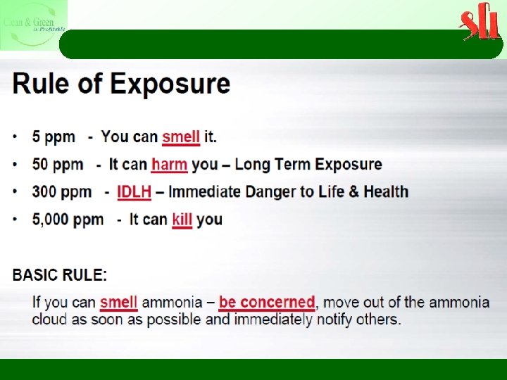
Selective Non Catalytic Reduction (SNCR) Potential Problems With SNCR Ø Not all of the ammonia injected into the SNCR system reacts with NOx, and the unreacted ammonia is called ammonia slip. Ø Ammonia in the flue gas stream can have a detectable odor at levels of 5 ppm or greater. Ø Health concerns can occur at ammonia slip levels of 25 ppm or greater Ø In addition, operating experience identified several concerns with the build up of ammonium bisulfite scale when burning sulfur-containing fuels
Principle of SCR is the process of using ammonia or urea in the presence of a catalyst to selectively reduce NOx emissions from exhaust gases. In the SCR system, anhydrous ammonia, usually diluted with air or steam or aqueous ammonia solution, is injected through a catalyst bed to reduce NOx emissions. A number of catalyst materials have been used, such as titanium dioxide, vanadium pentoxide, and zeolite-based materials. The catalyst is typically supported on ceramic materials Several different catalysts are available for use at different exhaust gas temperatures. Base metal catalysts are useful between 232 °C - 427 °C. For high temperature operations at 357 °C to 593 °C, zeolite catalysts containing precious metals such as platinum and palladium are useful. The two principal reactions in the SCR are: 4 NH 3 + 4 NO + O 2 4 N 2 + 6 H 2 O (predominant reaction as most NOx is NO) 4 NH 3 + 2 NO 2 + O 2 3 N 2 + 6 H 2 O
Principle of SCR In SCR system, ammonia is typically injected to produce a NH 3: NOx molar ratio of 1. 05– 1. 1: 1 to achieve a NOx conversion of 80– 90% with an ammonia slip of about 10 ppm The NOx removal efficiency depends on the flue gas temperature, the molar ratio of ammonia to NOx, and the flue gas residence time in the catalyst bed
SCR Operation SCR can be installed at a cement kiln after the PM control device. Low-dust system is required for longer catalyst life and lower danger of blockage. Catalysts are deactivated by the PM in the flue gas, and soot blowers are required to alleviate the problem. In a cement kiln application where the SCR is placed after the PM control, flue gas reheating would be required because the temperature of the kiln exhaust after PM control is lower than typical SCR operating temperatures. The disadvantage is the additional energy costs required to heat the cooled exhaust to achieve proper reaction temperatures in the catalyst.
Comparison of SNCR and SCR Design Criteria SNCR SCR NOx Reduction Efficiency (%) 70 -90 80 -95 870 -1200 232 -593 Reactor None Catalyst Waste disposal None Spent Catalyst Thermal Efficiency Debit (%) 0 -0. 3 0 Energy Consumption Low High I. D. Fan Capital Investment Low High Minor Major Low 3 -5 years catalyst life Ammonia/NOx Molar Ratio 1. 0 -1. 5 0. 8 -1. 2 Urea/NOx Molar Ratio 0. 5 -0. 75 Not applicable Ammonia Slip 5 -20 ppm 5 -10 ppm Easy Difficult Not Required Temperature Window o. C Plot Area Maintenance Retrofit Mechanical draft
Environmental Standards-TPP Notified on 7 th. December, 2015 & Effective from 7 th December, 2017. Period Emission Parameters Particulate Matter Standards 100 mg/ Nm 3 600 mg/ Nm 3 Power Plants Units Smaller than 500 MW SO 2 200 mg/ Nm 3 Commissioned Remarks Units Capacity 500 MW and above before 31 st Dec-2003 NOX 600 mg/ Nm 3 No Limit Given Hg Units Smaller than 500 MW 0. 03 mg/ Nm 3 Units Capacity 500 MW and above
Comparison of Environmental Standards Period Emission Parameters Standards Remarks Particulate Matter 50 mg/ Nm 3 600 mg/ Nm 3 Power Plants Commissioned After 1 st January, 2014 to 31 st Dec, 2016 SO 2 Units Smaller than 500 MW 200 mg/ Nm 3 Units Capacity 500 MW and above NOx 300 mg/ Nm 3 Hg 0. 03 mg/ Nm 3 For all Units
Comparison of Environmental Standards Period Emission Standards Remarks Parameters Particulate Matter 30 mg/ Nm 3 Power Plants to be Commissioned SO 2 100 mg/ Nm 3 NOx 100 mg/ Nm 3 Hg 0. 03 mg/ Nm 3 For all Units after 1 st Jan, 2017 For all Units
Air temperature vs NOx formation In Coal Fired Boilers : Ø Thermal NOx : 20 & Fuel NOx: 80% Ø Unlike the conventional boilers, where the flame temperature is much higher in the range of 1400 to 1500 deg C, atmospheric fluidized bed combustion (AFBC) / circulating fluidized bed combustion (CFBC) boilers are operated at much lower operating temperatures in the range of 850 to 900 deg C, the formation of thermal NOx is very low. The NOx levels can further be suppressed by air staging and flue gas recirculation apart from maintaining lower bed temperatures (850 to 900 deg C. )
Manufacture, Storage and Import of Hazardous Chemical Rules, 27 th November, 1989 and Amended on 19 th January, 2000 and Storage and Handling of NH 3
Rule 2. DEFINITIONS (e) "Hazardous Chemical " means - (i)any chemical which satisfies any of the criteria laid down in Part I of Schedule 1 or listed in Column 2 of Part II of this Schedule ; PART II, LIST OF HAZARDOUS AND TOXIC CHEMICALS Name of Chemical Name of Chemical 1. Acetaldehyde 2. Acetic acid 3. Acetic anhydride 4. Acetone 5. Acetone cyanohydrin 6. Acetone thiosemicarbazide 13. Adiponitrile 14. Aldicarb 15. Aldrin 16. Allyl alcohol 17. Allyl amine 18. Allyl chloride 19. Aluminium (powder) 20. Aluminium azide 21. Aluminium borohydride 22. Aluminium chloride 23. Aluminium fluoride 24. Aluminium phosphide 25. Amino diphenyl 26. Amino pyridine 27. Aminophenol -2 28. Aminopterin 29. Amiton 30. Amiton dialate 31. Ammonia 7. Acetonitrile 8. Acetylene 9. Acetylene tetra chloride 10. Acrolein 11. Acrylamide 12. Acrylonitrile
Rule 2 (h) "industrial activity" means- i. an operation or process carried out in an industrial installation referred to in Schedule 4 involving or likely to involve one or more hazardous chemicals and includes on-site storage or on-site transport which is associated with that operation or process, as the case may be; SCHEDULE -4 (See Rule 2(h) (i) 1. Installation for the production, processing or treatment of organic or inorganic chemicals using for this purpose, among others; (a) alkylation (b) Amination by ammonolysis (c) carbonylation (d) condensation (e) dehydrogenation (f) esterification (g) halogenation and manufacture of halogens (h) hydrogenation (i) hydrolysis (j) Oxidation (k) Polymerziation (l) Sulphonation (m) desulphurization, manufacture and transformation of sulphur containing compounds (n) nitration and manufacture of nitrogen containing compounds (o) manufacture of phosphorous-containing compounds (p) formulation of pesticides and of pharmaceutical products (q) distillation (r) extraction (s) solvation (t) mixing
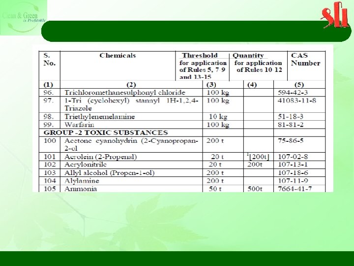
Rule 2 (n) "Threshold quantity" means, - (i) in the case of a hazardous chemical specified in Column 2 of Schedule 2, the quantity of that chemical specified in the corresponding entry in Columns 3 and 4 ; SCHEDULE 2 [See rule 2(e)(ii), 4(1)(b), 4(2) (1) and 6 (1) (b)] ISOLATED STORAGE AT INSTALLATIONS OTHER THAN THOSE COVERED BY SCHEDULE 4 S. No Chemicals Threshold Quantities (tonnes) For application of For application rules 4, 5, 7 to 9 and of rules 10 to 13 to 15 12 2 Ammonia 60 600
Rule 2 (n) "Threshold quantity" means, - (ii) in the case of a hazardous chemical specified in Column 2 of Part I of Schedule 3, the quantity of that chemical specified in the corresponding entry in Columns 3 & 4 of that part; SCHEDULE 3 [See Rule 2(e)(iii), 5 and 6(1) (a)] LIST OF HAZARDOUS CHEMICALS FOR APPLICATION OF RULES 5 AND 7 TO 15 (a) The quantities set-out-below relate to each installation or group of installations belonging to the same occupier where the distance between the installations is not sufficient to avoid, in foreseeable circumstances, any aggravation of major-accident hazards. These quantities apply in any case to each group of installations belonging to the same occupier where the distance between the installations is less than 500 metres.
Rule 4. General Responsibility of the Occupier During Industrial Activity – (1) these rules shall apply to, - (a) an industrial activity in which a hazardous chemical, which satisfies any of the criteria laid down in Part I of Schedule 1 or listed in Column 2 of Part II of this Schedule is, or may be, involved; and (b) isolated storage of a hazardous chemical listed in Schedule 2 in a quantity equal to or more than the threshold quantity specified in Column 3, thereof. (2) An occupier who has control of an industrial activity in terms of sub-rule (1) shall provide evidence to show that he has, - (a) identified the major accident hazards; and (b) taken adequate steps to (i) prevent such major accidents and to limit their consequences to persons and the environment; (ii) provide to the persons working on the site with the information, training and equipment including antidotes necessary to ensure their safety.
SCHEDULE -5 (See Rules, 2(b) and 3) S. No Authority (ies) with legal backing Duties and corresponding Rule Description 1 Ministry of Environment and Forests under Environment (Production) Act, 1986. Notification of hazardous chemicals as per Rules 2(e)(i), 2(e) (ii) & 2(e) (iii) -NH 3 mentioned in Part II of schedule 1 Central Pollution Control Board or State Pollution Control Board 1[or Committee] under Environment (Protection) Act, 1986 as the case may be. Enforcement of directions and procedures in respect of isolated storage of hazardous chemicals, regarding- (i) Notification of major accidents as per Rules 5(1) and 5(2) (ii) Notification of sites as per Rules 7 to 9. (iii) Safety reports in respect of isolated storages as per Rule 10 to 12. (iv) Preparation of on-site emergency plans as per Rule 13. - Inform with in 48 hrs if a major accident occurs on a site - Full analysis by authority and inform the MOEF&CC within 90 days - Submission of safety report at least 90 days prior to undertake any industrial activity - Safety audit once in a year - Preparation of on-site emergency plan containing how major accidents will be dealt 3 - Inspection of the industrial activity at least once in a year
SCHEDULE -5 (See Rules, 2(b) and 3) S. No Authority (ies) with legal backing Duties and corresponding Rule Description 4 Chief Inspector of Factories appointed under the Factories Act, 1948. Enforcement of directions and procedures in respect of industrial installations and isolated storages covered under the Factories Act, 1948, dealing with hazardous chemicals and pipelines including inter-state pipelines regarding- (i) Notification of major accidents as per Rule 5(1) and 5 (2). (ii) Notification of sites as per Rules, 7 to 9. (iii) Safety reports as per Rules, 10 to 12. (iv) Preparation of on-site emergency plans as per Rule 13. - Inform with in 48 hrs if a major accident occurs on a site - Full analysis by authority and inform the MOEF&CC within 90 days - Prior approval for undertaking any industrial activity - Submission of safety report at least 90 days prior to undertake any industrial activity - Safety audit once in a year - Preparation of on-site emergency plan containing how major accidents will be dealt Preparation of off-site emergency plans in consultation with District Collector or District Emergency Authority as per S. No. 9 of this schedule.
SCHEDULE -5 (See Rules, 2(b) and 3) S. No Authority (ies) with legal backing Duties and corresponding Rule Description 8 Chief Controller of Explosives appointed under the Indian Explosive Act and Rules, 1983 Enforcement of directions and procedures in respect of Industrial installation and isolated storages dealing with hazardous chemicals and pipelines including inter-state pipelines regarding. (a) Notification of major accident as per rule 5; (b) Approval and notification of sites as per rule 7; (c) Safety report and safety audit reports as per rules 10 to 12; (d) Acceptance of On-site Emergency plans as per rule 13; (e) Assisting the District Collector in the preparation of Off-Site emergency plans as per serial number 9 of this Schedule. - Inform with in 48 hrs if a major accident occurs on a site - Full analysis by authority and inform the MOEF&CC within 90 days - Prior approval for undertaking any industrial activity - Submission of safety report at least 90 days prior the undertake any industrial activity - Safety audit once in a year - Preparation of on-site emergency plan containing how major accidents will be dealt
SCHEDULE -5 (See Rules, 2(b) and 3) S. No Authority (ies) with legal backing Duties and corresponding Rule Description 9 District Collector or District Emergency Authority designated by the State Government Preparation of off-site emergency plans as per Rule 14 It shall be the duty of the concerned authority to prepare and keep up-to-date an adequate off-site emergency plan containing particulars how emergencies relating to a possible major accident on that site will be dealt with and in preparing that plan the concerned authority shall consult the occupier, and such other persons as it may deem necessary.
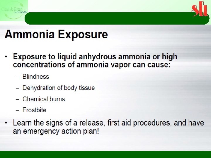
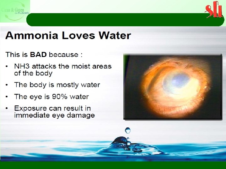
Ammonia Characteristics Ø Ammonia is a colourless gas with a characteristic pungent smell. It is lighter than air, its density being 0. 589 times that of air. It is easily liquefied due to the strong hydrogen bonding between molecules; the liquid boils at − 33. 3 °C (− 27. 94 °F), and freezes at − 77. 7 °C (− 107. 86 °F) to white crystals. Ø Ammonia liquid must be stored under pressure or at low temperature. A storage vessel capable of 250 psi (1. 7 MPa) is suitable to contain the liquid.
Thanks environment@shreecementltd. com