Nonlinear Control of a Grid Connected Wind Turbine

Nonlinear Control of a Grid Connected Wind Turbine Marwa Hassan

Content �Introduction �Nonlinear �Results Control Design of Simulation �Conclusion

Introduction Due to the enormous problem faces traditional energy sources it become more essential to search for alternative energy sources The wind system based on the Doubly Fed Induction Generator DFIG has become more effective in industry in the last few years due to their advantage compared to the permanent magnet synchronous generator as it provide better results when compared to cost, size and weight

Introduction In this paper, a non-linear control design for a Doubly Fed Induction Generator (DFIG) that is connected to grid is proposed. The main purpose of this design is to improve power efficiency while ensuring smooth voltage performance. Two models have been studied the first one represents the doublyfed induction generator while the second relates to the grid side converter command models.

Nonlinear Control Design

Nonlinear Control Design

Non linear model of DIFG

Control of d-axis rotor current

Control of q-axis rotor current

Non linear grid side converter model d-axis control

Simulation and Results � Two case studies have been developed and simulated via MATLAB � The Maximum Power Point Tracking MPPT is chosen and the pitch angle is adjusted at 89 degree for both cases.

� For the first case we choose to � design a feedback that controls the stable zeros of the system �a new desired zero L = 0: 4 is chosen to enhance the stability. � The stator voltage of the DFIG in this case is set to 0. 7 p. u and the reference value of the direct axis current d is set to 0. 2 p. u. Simulation and Results

Simulation and Results � Two cases were developed. The first case investigated the performance of controller when it’s directly connected to the DFIG while in the second case the focus was in investigating the behavior of the DFIG when it’s connected to the network and under the operating condition of setting power factor to one. � The following block diagrams illustrated the design process of the DFIG model and the second case scenario.

Fig. 1 Simplified Block diagram of the Asymptotic output tracking technique for the DFIG model

Fig. 2 Block diagram of the Asymptotic output tracking for the Grid side model

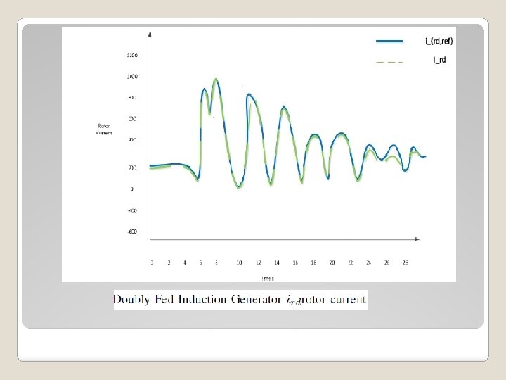
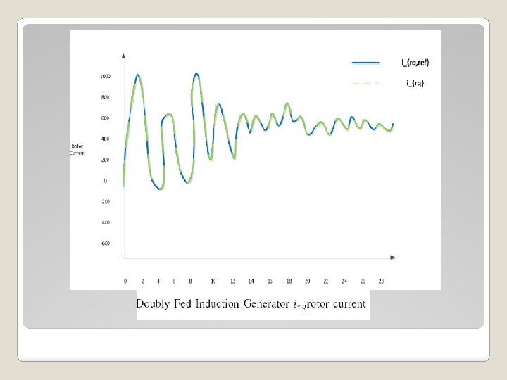
First case � Figure 3; 4 illustrated the rotor side reference signal and the generated current signals verses time in seconds in the direct and quadratic frames respectively. � It can be noticed from Figure 3; 4 that the proposed control technique succeeded in reproducing a current signal that coincides with the required reference signal in both cases. � Figure 5 presents the continuous bus voltage of the DFIG regulated to the standard reference voltage fixed at 1000 V. It is clear that in spite of fluctuation of the wind the voltage remain stationary

Doubly Fed Induction Generator continuous bus voltage

Second Case � In the second case the stator of the DFIG was directly connected to the grid while its rotor was connected to it via a cascade (Rectifier, Inverter and Filter) � In order to evaluate the grid side model the power factor was set to one , thus only the direct rotor current will be produced. � The voltage on the output of the inverter will suffer from disturbance signals formed by the original of frequency f = 50 Hz and other signals. � A passive R-L filter was used to eliminate harmonics

Power factor of DFIG connected to Grid

The rotor direct current of DFIG connected to grid

Conclusion The aim of this work is to introduce a non-linear control technique that asymptotically tracks the rotor current of the grid-connected wind turbine based on Double Fed Induction Generator (DIFG). the idea is to produce a certain rotor current in order to meet a specific requirement of active and reactive power production � � Two cases have been developed based on the DIFG model and the grid side converter command model. � The results in both cases shown that the control approach succeeded in reproducing an output signal that coincides with the required reference signal
- Slides: 23