
Newly optimized CLICGR 1 design Hao Zha Alexej

- Slides: 21
Newly optimized CLIC-G*-R 1 design Hao Zha, Alexej Grudiev (CERN) 18/06/2015 High Gradient work shop 2015 in Tsinghua University
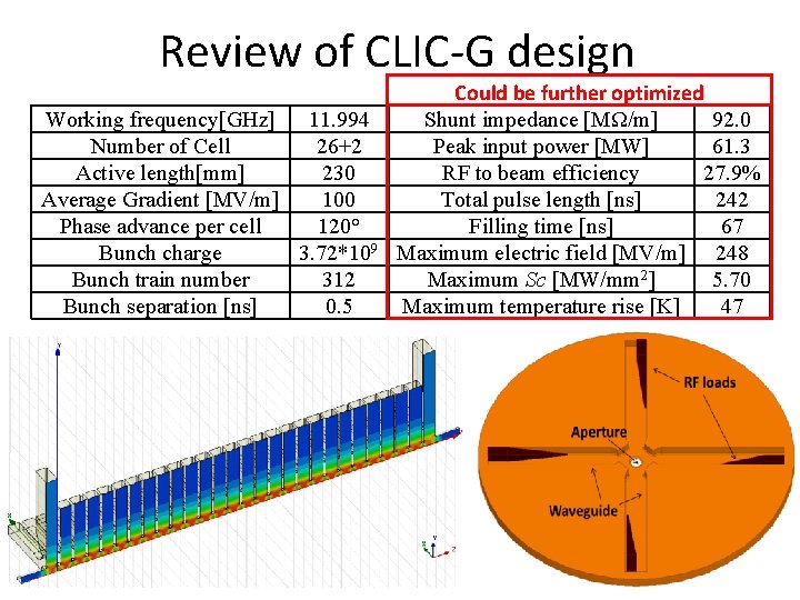
Review of CLIC-G design Working frequency[GHz] 11. 994 Number of Cell 26+2 Active length[mm] 230 Average Gradient [MV/m] 100 Phase advance per cell 120° Bunch charge 3. 72*109 Bunch train number 312 Bunch separation [ns] 0. 5 Could be further optimized Shunt impedance [MΩ/m] 92. 0 Peak input power [MW] 61. 3 RF to beam efficiency 27. 9% Total pulse length [ns] 242 Filling time [ns] 67 Maximum electric field [MV/m] 248 Maximum Sc [MW/mm 2] 5. 70 Maximum temperature rise [K] 47
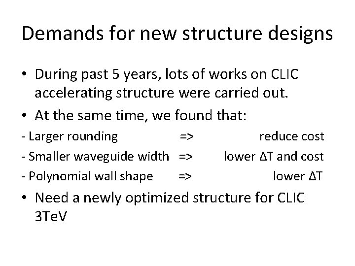
Demands for new structure designs • During past 5 years, lots of works on CLIC accelerating structure were carried out. • At the same time, we found that: - Larger rounding => reduce cost - Smaller waveguide width => lower ΔT and cost - Polynomial wall shape => lower ΔT • Need a newly optimized structure for CLIC 3 Te. V
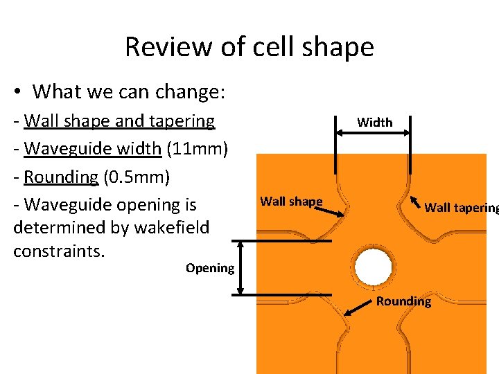
Review of cell shape • What we can change: - Wall shape and tapering - Waveguide width (11 mm) - Rounding (0. 5 mm) - Waveguide opening is determined by wakefield constraints. Width Wall shape Wall tapering Opening Rounding
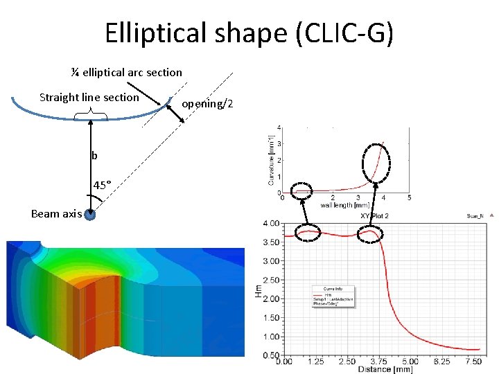
Elliptical shape (CLIC-G) ¼ elliptical arc section Straight line section b 45° Beam axis opening/2
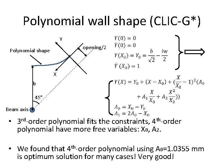
Polynomial wall shape (CLIC-G*) Y opening/2 Polynomial shape X b 45° Beam axis • 3 rd-order polynomial fits the constraints, 4 th-order polynomial have more free variables: X 0, A 2. • We found that 4 th-order polynomial using A 0=1. 0355 mm is optimum solution for many cases! Very good!
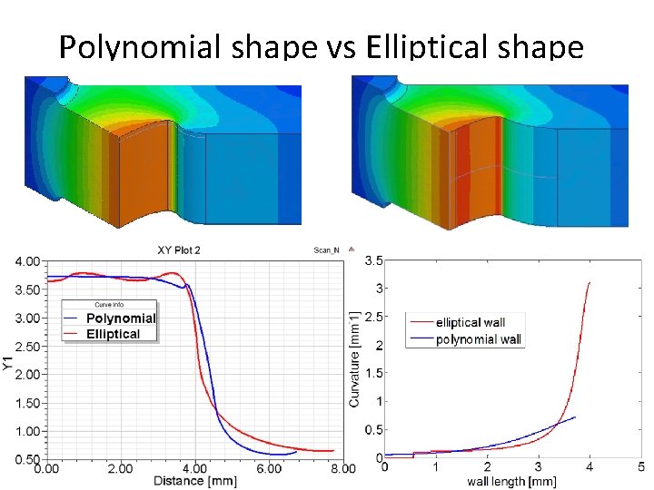
Polynomial shape vs Elliptical shape
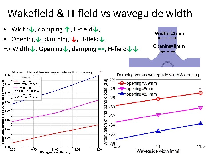
Wakefield & H-field vs waveguide width • Width↓, damping ↑, H-field↓, • Opening↓, damping ↓, H-field↓, => Width↓, Opening↓, damping ==, H-field↓↓. Width=11 mm Opening=8 mm
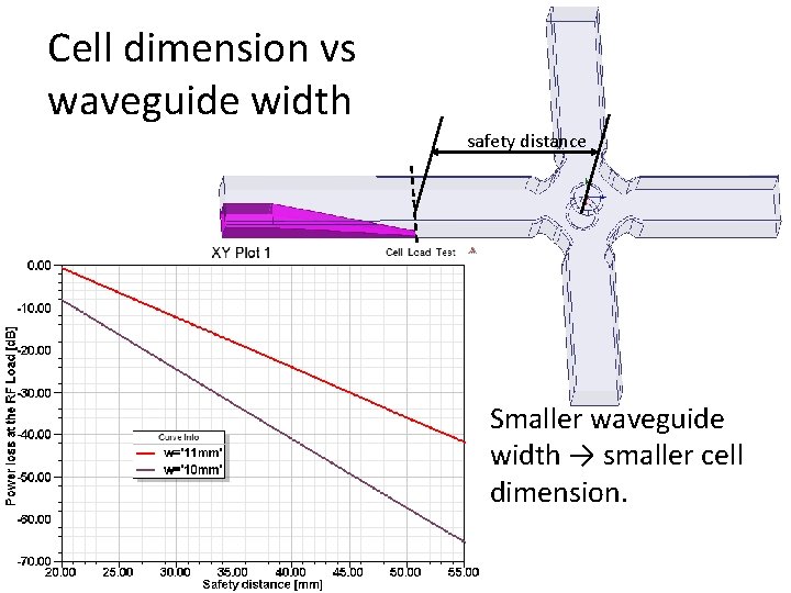
Cell dimension vs waveguide width safety distance • Smaller waveguide width → smaller cell dimension.
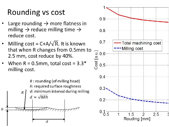
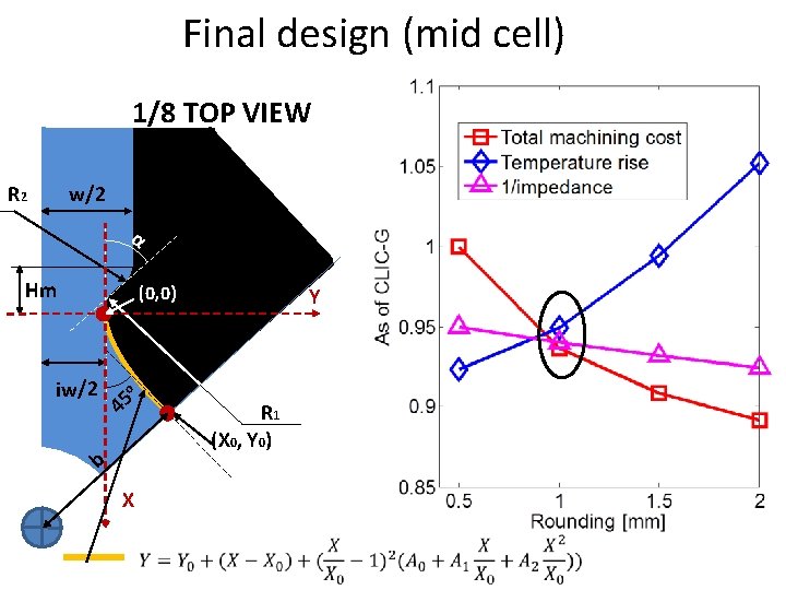
Rounding vs cost • R h d
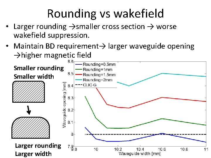
Rounding vs wakefield • Larger rounding →smaller cross section → worse wakefield suppression. • Maintain BD requirement→ larger waveguide opening →higher magnetic field Smaller rounding Smaller width Larger rounding Larger width
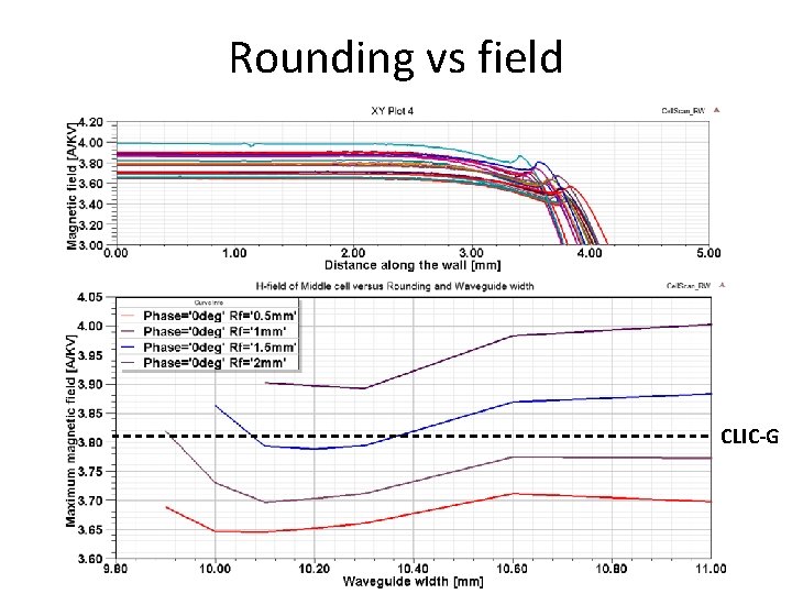
Rounding vs field CLIC-G
Final design (mid cell) 1/8 TOP VIEW R 2 w/2 α Hm (0, 0) iw/2 Y o 45 R 1 (X 0, Y 0) b X
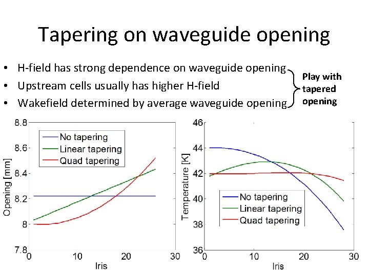
Tapering on waveguide opening • H-field has strong dependence on waveguide opening • Upstream cells usually has higher H-field • Wakefield determined by average waveguide opening Play with tapered opening
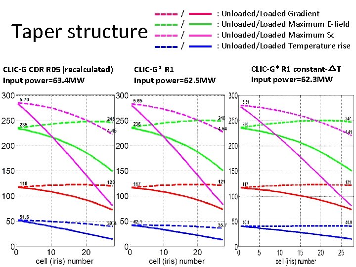
Taper structure CLIC-G CDR R 05 (recalculated) Input power=63. 4 MW / : Unloaded/Loaded Gradient / : Unloaded/Loaded Maximum E-field / : Unloaded/Loaded Maximum Sc / : Unloaded/Loaded Temperature rise CLIC-G* R 1 Input power=62. 5 MW CLIC-G* R 1 constant-△T Input power=62. 3 MW
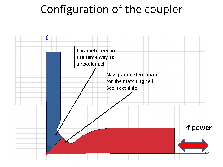
Configuration of the coupler Parameterized in the same way as a regular cell New parameterization for the matching cell See next slide rf power
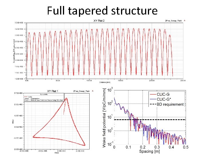
Full tapered structure
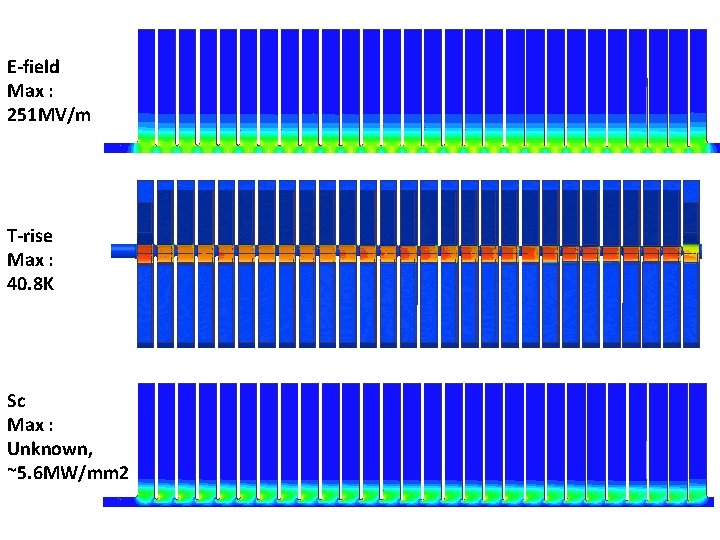
E-field Max : 251 MV/m T-rise Max : 40. 8 K Sc Max : Unknown, ~5. 6 MW/mm 2
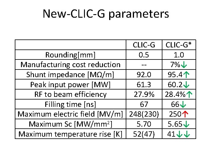
New-CLIC-G parameters CLIC-G* Rounding[mm] 0. 5 1. 0 Manufacturing cost reduction -7%↓ Shunt impedance [MΩ/m] 92. 0 95. 4↑ Peak input power [MW] 61. 3 60. 2↓ RF to beam efficiency 27. 9% 28. 4%↑ Filling time [ns] 67 66↓ Maximum electric field [MV/m] 248(230) 250↑ Maximum Sc [MW/mm 2] 5. 70 5. 65↓ Maximum temperature rise [K] 52(47) 41↓↓
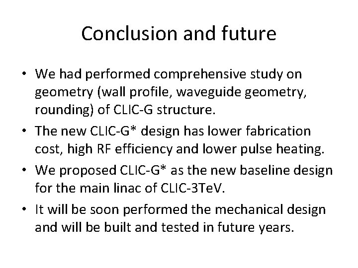
Conclusion and future • We had performed comprehensive study on geometry (wall profile, waveguide geometry, rounding) of CLIC-G structure. • The new CLIC-G* design has lower fabrication cost, high RF efficiency and lower pulse heating. • We proposed CLIC-G* as the new baseline design for the main linac of CLIC-3 Te. V. • It will be soon performed the mechanical design and will be built and tested in future years.
Thanks