New Flare Requirements in MACT CC Jeff Greif


- Slides: 56

New Flare Requirements in MACT CC Jeff Greif Air Permits Division Texas Commission on Environmental Quality Environmental Trade Fair 2017

Objectives 1. Requirements 2. Significant Changes 3. TCEQ Perspective & Permitting

The Past

Modern History • 40 CFR § 60. 18 • 40 CFR § 63. 11(b) • RG-109 DRAFT

Permit Boiler Plate

The Focus 1. Always Have a Flame 2. No Smoke 3. Keep It Lit A. Sufficient Heating Value B. Limited Velocity 4. Monitor

The Future

January 30, 2019

Changes § 60. 18 § 63. 670

Changes? § 63. 11(b) 1. Always Have a Flame 2. No Smoke 3. Keep It Lit A. Sufficient Heating Value B. Limited Velocity 4. Monitor § 63. 670 1. Operate With a Pilot Flame 2. No Smoke or Tell Me All About It! 3. Keep It Lit A. Count the Added Steam and Air Effect on Heating Value B. Limited Velocity 4. MONITOR & Report!

Pilot Flame

Pilot Flame “…when regulated material is routed to the flare. ” VS. “…at all times vent gas may be directed to the flare(s). ”

Visible Emissions. . …No Steam assist off Steam assist on

No Visible Emissions Old Hat • Method 22 • 5 minutes in 2 hours What’s New • Specify the Smokeless Design Capacity • Monitor

Smokeless Design Capacity Air Assisted Flare Measured at 99. 4% Efficiency

Visible Emissions & TCEQ Permits No Smoking Over 5 min in 2 hr Monitor per § 63. 670(h)

VE Monitoring Method 22 Daily Video Surveillance

Velocity and Heat Content “…regulated material is routed to the flare for at least 15 -minutes”

Flare Tip Velocity • 60 ft/s • Vmax to 400 ft/s

Flare Tip Velocity Log 10 (Vmax) = NHVvg + 1, 212 850

I. D. M Flare Tip Area I. D. M Pilot Stability Tabs Modules

Flare Tip Area Calculation Atip-unob = NM * (∏ * (I. D. M)2/4 – XT * AST Where: Atip-unob = Unobstructed Cross Sectional Area of Flare Tip I. D. M = Inside Diameter of One Tip Module NM = Number of Modules XT = Number of Stability Tabs per Module AST = Area of a Stability Tab

Flare Tip

NHVvg Net heating value of flare vent gas, Btu/scf Remember § 63. 641 Definitions

The New Standards Combustion Zone Operating Limits CO 2 H 2 O NOX CO fuel Dilution Operating Limits

What Does This Mean?

NHVcz versus NHVdil NHVcz NHVdil All Flares Receiving Perimeter Assist Air for

NHVvg Composition Monitoring Continuous Compositional Analysis (15 -min) or Method 18 Canister (8 -hr) -------------Continuous Calorimeter w/ H 2 Option --------------Demonstrated Consistent Composition

NHVvg from Continuous Monitors Options: Feed-Forward or Direct Calculation Data applied in the following 15 -min block vs. Data applied in the block it is available

15 -Minute Block Time 8: 00 to 8: 15, 8: 15 to 8: 30, etc.

GC Heating Value Example 12: 00 12: 15 12: 30 12: 45 1: 00 12: 05 12: 10 12: 23 12: 25 12: 38 12: 40 12: 53 • • Event Starts Measurement A Taken Result A (560) Available Measurement B Taken Result B (340) Available Measurement C Taken Result C (300) Available

GC Heating Value Example Feed Forward 12: 00 12: 15 12: 30 12: 45 1: 00 12: 05 12: 10 12: 23 12: 25 12: 38 12: 40 12: 53 560 Btu/scf 340 Btu/scf 300 Btu/scf Result A (560) Available Result B (340) Available Result C (300) Available

GC Heating Value Example Direct Calculation 12: 00 12: 15 12: 30 12: 45 1: 00 12: 05 12: 10 12: 23 12: 25 12: 38 12: 40 12: 53 560 Btu/scf 340 Btu/scf 300 Btu/scf Result A (560) Available Result B (340) Available Result C (300) Available

Hmmm… Time NHVvg Feed Forward Direct 12: 10 560 560 12: 25 340 560 12: 40 300 560 340

Flare Supplemental Gas Purchased Natural Gas 925 Btu/scf Heat Value Accounting from Flow

Flow Monitoring • Flare Vent Gas • Steam Assist – All • Air Assist – Premix – Perimeter • Supplemental Natural Gas

Flow Monitoring Methods are Flexible Standard Conditions are Not 68°F 1 Atm 385. 3 SCF/lb-mol

Flow Monitoring Options • Measure Volumetric Flow or Mass Flow • Use Fan Speed or Power With Fan Curves • Use Molecular Weight, Pressure, and Temperature With Engineering Calculations

Objective The Number of Standard Cubic Feet Q Q

Steam Assist Style Flare Tip • Perimeter Steam • Uses S/A Tubes • High Smokeless

Upper Steam Ring Injection Nozzles Steam Assist Style Flare Tip Lower Steam Ring Outlet for Steam/Air Mixture Flare Gas Unobstructed Exit Area is Gap Between the Tubes Over the Shell Upper Steam Ring Lower Steam Ring Center Steam Inlet Flange Injecting Steam Only Directly Into Flare Barrel Lower Steam Injector Into Internal Tube With Air Inspiration Flare Gas Inlet Range Upper Steam Ring Inlet

Assist Air Premix Assist Air ---------Perimeter Assist Air

Air Assist Style Flare Tip

Steam and Air Issue Flare Tip With Lower Steam Flare tip with lower induction steam tubes addition. Legend Ambient Air Steam Flare Gas

Combustion Zone Gas NHVcz 270 Btu/scf NHVcz = Qvg x NHVvg (Qvg + Qs + Qa, premix)

Net Heating Value Dilution Parameter NHVdil = 22 Btu/ft 2 Qvg x Diam x NHVvg (Qvg + Qs + Qa, premix + Q a, perimeter)

Flare Monitoring Systems Continuous Parameter Monitoring System (CPMS) • • • Operational Requirements Monitoring Plan Out of Control Periods Data Reduction Gas Chromatographs

CPMS Operation • • Table 13 Readily Accessible 15 Minute Cycles Minimum Continuous When Regulated Materials Flow

Table 13 Parameters • Temperature • Flow Rate for All Flows Other Than Flare Vent Gas • Flare Vent Gas Flow Rate • Pressure • Net Heating Value by Calorimeter • Net Heating Value by Gas Chromatograph • Hydrogen Analyzer

Table 13 Minimum Accuracy Requirements Temp ± 1% or 2. 8°C, which ever is greater

Table 13 Calibration Requirements • Cal check annually • Cal check if measurement exceeds range for 24 hrs or install new • Inspect components and electrical connections quarterly, unless redundant • Record results • Locate so representative and shielded

Emergency Flaring Provisions § 63. 670(o) 1) Plan 2) Submit the Plan 3) Smoking … Root Cause 4) Corrective Action

Emergency Flaring Provisions • • Force Majeure Good Maintenance No Mistakes 1 Event / 3 Years EPA

Emergency Flaring Provisions • • Operator Error Poor Maintenance 2 Same Cause 3 in 3

Flare Systems

And that is all I have Good to say about that! Reference Material: Parameters for Properly Designed and Operated Flares Contacts: Jeff Greif – jeff. greif@tceq. texas. gov Rick Goertz – richard. goertz@tceq. texas. gov
 Jeff greif
 Cast restoration
 Tatjana greif
 Greif japanese
 Absent grief
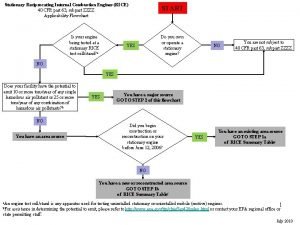
 Subpart zzzz flowchart
 Mact zzzz
 Rice mact
 Rice mact
 Modified booth algorithm
 Civica app
 Tony camilli
 Balanced force technique
 Supposing a snowmobile is equipped with a flare
 Primary flare in inlay
 Avaya aura conferencing
 Temporal flare
 Tfl counterstrain
 Microdose flare protocol
 Fillet weld symbol all around
 J-groove weld
 Gamma flare
 Bloom and lens flare
 Aqueous flare
 Hewitt
 Purulent uveitis
 Eye nomenclature
 Skirt in tooth preparation
 Iridocylitis
 Akihiro nakao
 What does flaring nostrils mean
 Eso dark flare
 Flare radius
 Flare stack wire
 Nbn requirements for new homes
 Examples of inverted commas
 New york pennsylvania new jersey delaware
 New oil and new wineskin
 Movies new hartford
 Characteristics of the articles of confederation
 New-old approach to creating new ventures
 New marketing realities
 Njbta
Njbta New classical macroeconomics
 Chapter 16 toward a new heaven and a new earth
 Neil thisse is a loyalist who fled the colonies
 New classical and new keynesian macroeconomics
 New nationalism vs new freedom venn diagram
 Walmart vs target swot analysis
 Jeff kimble caltech
 Dr jeff masters
 Jeff doucet
 Jeff dugger
 Product launch formula
 Participants of money market
 Little boy blue by darren sardelli
 Anselm kiefer heroic symbols
