Networking Computer network A collection of computing devices


 A network that connects a relatively small")


 A network that connects two or more")
 The communication infrastructures that have been developed")


 established the Open Systems Interconnection")


 • UDP stands for User Datagram Protocol – It is an")


 is chiefly used to translate")


 A half duplex system provides communication in")
 A full duplex system or sometimes called double duplex, allows")


 It is used to connect different LANs in a")
 A wide area network is a connection of two")


 model is a")


 ETHERNET: Ethernet is a LAN architecture which was developed by Xerox.")


")


 • Peak throughput")

 • Ethernet by definition is a broadcast protocol – Any")
: It is two satellite ground")
: home telephone is connected to a circuit switch network")


 of the OSI")


 allows for sending multiple signals through a single medium")


 • TDM is accomplished by creating phase delays each")
 • All signals are sent simultaneously, each assigned its own frequency")
 • WDM is the combining of light by using different wavelengths")


 and physical layer")


 is")


- Slides: 173
Networking • Computer network A collection of computing devices that are connected in various ways in order to communicate and share resources Usually, the connections between computers in a network are made using physical wires or cables However, some connections are wireless, using radio waves or infrared signals
Networking • The generic term node or host refers to any device on a network • Data transfer rate The speed with which data is moved from one place on a network to another • Data transfer rate is a key issue in computer networks
Networking • Computer networks have opened up an entire frontier in the world of computing called the client/server model Client/Server interaction
Networking • File server A computer that stores and manages files for multiple users on a network • Web server A computer dedicated to responding to requests (from the browser client) for web pages
Types of Networks • Local-area network (LAN) A network that connects a relatively small number of machines in a relatively close geographical area
Types of Networks • Various configurations, called topologies, have been used to administer LANs – Ring topology A configuration that connects all nodes in a closed loop on which messages travel in one direction – Star topology A configuration that centers around one node to which all others are connected and through which all messages are sent – Bus topology All nodes are connected to a single communication line that carries messages in both directions
Types of Networks Various network topologies • A bus technology called Ethernet has become the industry standard for local-area networks
Types of Networks • Wide-area network (WAN) A network that connects two or more local-area networks over a potentially large geographic distance Often one particular node on a LAN is set up to serve as a gateway to handle all communication going between that LAN and other networks Communication between networks is called internetworking The Internet, as we know it today, is essentially the ultimate wide-area network, spanning the entire globe
Types of Networks • Metropolitan-area network (MAN) The communication infrastructures that have been developed in and around large cities
So, who owns the Internet? Well, nobody does. No single person or company owns the Internet or even controls it entirely. As a wide-area network, it is made up of many smaller networks. These smaller networks are often owned and managed by a person or organization. The Internet, then, is really defined by how connections can be made between these networks.
Types of Networks Local-area networks connected across a distance to create a widearea network
Internet Connections • Internet backbone A set of high-speed networks that carry Internet traffic These networks are provided by companies such as AT&T, GTE, and IBM • Internet service provider (ISP) A company that provides other companies or individuals with access to the Internet
Internet Connections • There are various technologies available that you can use to connect a home computer to the Internet – A phone modem converts computer data into an analog audio signal for transfer over a telephone line, and then a modem at the destination converts it back again into data – A digital subscriber line (DSL) uses regular copper phone lines to transfer digital data to and from the phone company’s central office – A cable modem uses the same line that your cable TV signals come in on to transfer the data back and forth
Internet Connections • Broadband A connection in which transfer speeds are faster than 128 bits per second – DSL connections and cable modems are broadband connections – The speed for downloads (getting data from the Internet to your home computer) may not be the same as uploads (sending data from your home computer to the Internet)
Packet Switching • To improve the efficiency of transferring information over a shared communication line, messages are divided into fixed-sized, numbered packets • Network devices called routers are used to direct packets between networks Messages sent by packet switching
Open Systems • Proprietary system A system that uses technologies kept private by a particular commercial vendor One system couldn’t communicate with another, leading to the need for • Interoperability The ability of software and hardware on multiple machines and from multiple commercial vendors to communicate Leading to • Open systems Systems based on a common model of network architecture and a suite of protocols used in its implementation
Open Systems • The International Organization for Standardization (ISO) established the Open Systems Interconnection (OSI) Reference Model The layers of the OSI Reference Model • Each layer deals with a particular aspect of network communication
Network Protocols • Network protocols are layered such that each one relies on the protocols that underlie it • Sometimes referred to as a protocol stack Layering of key network protocols
TCP/IP • TCP stands for Transmission Control Protocol TCP software breaks messages into packets, hands them off to the IP software for delivery, and then orders and reassembles the packets at their destination • IP stands for Internet Protocol IP software deals with the routing of packets through the maze of interconnected networks to their final destination
TCP/IP (cont. ) • UDP stands for User Datagram Protocol – It is an alternative to TCP – The main difference is that TCP is highly reliable, at the cost of decreased performance, while UDP is less reliable, but generally faster
High-Level Protocols • Other protocols build on the foundation established by the TCP/IP protocol suite – Simple Mail Transfer Protocol (SMTP) – File Transfer Protocol (FTP) – Telnet – Hyper Text Transfer Protocol (http)
MIME Types • Related to the idea of network protocols and standardization is the concept of a file’s MIME type – MIME stands for Multipurpose Internet Mail Extension – Based on a document’s MIME type, an application program can decide how to deal with the data it is given
MIME Types Some protocols and the ports they use
Firewalls • Firewall A machine and its software that serve as a special gateway to a network, protecting it from inappropriate access – Filters the network traffic that comes in, checking the validity of the messages as much as possible and perhaps denying some messages altogether – Enforces an organization’s access control policy
Firewalls A firewall protecting a LAN
Network Addresses • Hostname A unique identification that specifies a particular computer on the Internet For example matisse. csc. villanova. edu condor. develocorp. com
Network Addresses • Network software translates a hostname into its corresponding IP address For example 205. 39. 145. 18
Network Addresses • An IP address can be split into – network address, which specifies a specific network – host number, which specifies a particular machine in that network An IP address is stored in four bytes
Domain Name System • A hostname consists of the computer name followed by the domain name • csc. villanova. edu is the domain name – A domain name is separated into two or more sections that specify the organization, and possibly a subset of an organization, of which the computer is a part – Two organizations can have a computer named the same thing because the domain name makes it clear which one is being referred to
Domain Name System • The very last section of the domain is called its top-level domain (TLD) name Top-level domains, including some relatively new ones
Domain Name System • Organizations based in countries other than the United States use a top-level domain that corresponds to their two-letter country codes Some of the top-level domain names based on country codes
Domain Name System • The domain name system (DNS) is chiefly used to translate hostnames into numeric IP addresses – DNS is an example of a distributed database – If that server can resolve the hostname, it does so – If not, that server asks another domain name server
Network Basics Chapter 1
What is Networking? v Networking is one of the excellent concepts in the field of computers. It enables users at geographical distances to communicate and share data at an excellent speed. This not only reduces time consumption but also reduce the cost of many systems. Networking can be done within a room, organization, city, country or world. The basic purpose of making a network is communication and resource sharing.
What is Computer Network? v Computer network is an interconnection of independent computers in some manner through communication medium to share resources like hardware, software and peripheral devices.
Need of Computer Network? v Now the question arises what is the need of computer network? So, • Computer network is used for connecting computers between various buildings of an organization. • Exchange of data and information amongst the users Via computer network. • In education area and to share information over the geographical wide area. • Also used for sharing software and database.
Advantage o Data transfer and sharing with a wide great speed. o As speed of transfer and sharing is very high, so it reduces the time as well as stationary products too like floppy disk, cd’s etc. o Data encryption is possible with the help of computer network. o Communication is easy with the help of emails.
Disadvantage ü Computer are connecting with the help of cables which may also get damage. ü Installation cost is very high. ü Maintenance cost is high. ü Server failure is also a disadvantage of computer network.
Elements of Computer Network Ø Sender: It is the computer which want to give the message to some one. Ø Receiver: It is the computer which receives the data from sender who wants to communicate. Ø Communication Medium: It is the medium through which sender connects to receiver. It can be wire or wireless. Ø Protocols: Protocols is defined as a set of rules which governs data communication.
Types of Communication § Communication is only in one direction or in both directions. Based on this communication system is classified as: - • Simplex System(In one direction): Simplex system is a communication mode in which only one signal is transmitted, and it always goes in same direction.
• Half Duplex(Bidirectional but not Simultaneously) A half duplex system provides communication in both direction but not simultaneously i. e once a party begins receiving a signal, it must wait for the transmitter to stop transmitting. E. g. Walkie-talkie.
• Full Duplex(Bidirectional) A full duplex system or sometimes called double duplex, allows communication in both direction. Landlines, mobile phones network or full duplex, since they allows both callers to speak and heard at the same time.
Network Models q Peer to Peer Network: “Peer to peer is a communication model in which each party has the same capabilities and either party can initiate a communication session”. In this individuals have personal machine which are equally powerful.
q Client Server Network • Client: Individual workstation in a network is client. • Server: Data stored on powerful computers called server who provides services. In this the data store on powerful computers called servers who provide services. They are maintained and controlled by system administrator , in contrast who wants the services called clients.
Computer Networks There are three types of a computer network: § Local Area Network (LAN): LANs are very small networks with a single building or campus of up to few kilometers. The data rate in LAN is of the order of Mbps.
§ Metropolitan Area Network (MAN) It is used to connect different LANs in a city: It resides between LAN and WAN. It connects computers within a city or group of nearby corperate offices. The implementations for MAN provides transfer rates from 34 Mbps to 150 Mbps.
§ Wide Area Network (WAN) A wide area network is a connection of two or more computers which are geographically dispersed. It has no longer distance communication than LAN. It uses public network like telephone network or microwave relays for communication facilities.
Network Topologies v It is the way in which the computers are connected in a network is called topology. Network topology is the arrangement of the various elements (links , nodes etc) of a computer network. There are various network topologies o Star topology o Bus topology o Tree topology o Mesh topology o Ring topology
o Star Topology It consist of several devices or computers connected to one centralised computer. This central computer is known as server and other computers connected to server are known as clients or workstation.
o Bus Topology The Bus topology is also known as horizontal topology. This topology is very common among local area networks. In this network each computer is connected to a single communication line or cable with an interface. Thus every computer can directly communicate with other computer or device in the network.
o Tree Topology A tree network links computers in a hierarchical fashion and requires information to flow through the branches. It uses simple software to control the network. The topology provides a concentration point for control and error resolution.
o Mesh Topology In a mesh topology every device has a dedicated point to point link to every other device. A mesh topology in which every device connects to every other is called full mesh. It is robust because the failure of single computer does not bring down the entire network.
o Ring Topology A ring network consist of several computers or devices connected to each other in a closed loop by a single communication channel. There is no need of central computer or server in this network. The data travels around the ring to each station in turn until it reaches at the desire computer or device.
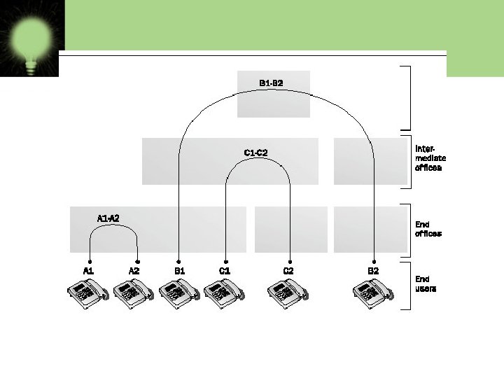
Switching Techniques For transmission of data beyond local area, communication is achieved by transmitting data from source to destination through a network of intermediate nodes. Theses nodes are called switching nodes. This method of switching data is called switching. The various switching methods are: § Circuit Switching § Packet Switching § Message Switching
§ Circuit Switching There is a direct physical connection between two devices established. Three phases are involved • Circuit establishment: Before any message can be transmitted an end to end circuit must be established. • Data transfer: After the circuit establishment data is transferred through the network. • Circuit disconnect: After some period of data transfer the connection is terminated usually by the action of one of the two stations.
§ Message Switching In this no physical path is established between sender and receiver. Instead when sender has the block of the data to send , it is stored in first switching office i. e, router and then forward later. This is also called store and forward network.
§ Packet Switching In this type the message is transmitted in the form of bits of variable length block called packets. The maximum length of packet is established by the network. Each packet contains header with control information along with the data.
Chapter 2 OSI MODEL
OSI Reference Model Ø OSI MODEL: -The Open Systems Interconnection (OSI) model is a reference tool for understanding data communications between any two networked systems. It divides the communications processes into seven layers. Each layer both performs specific functions to support the yers above it and offers services to the layers below it. The three lowest layers focus on passing traffic through the network to an end system. overview www. globalknowledge. com
The Physical Layer Ø The physical layer of the OSI model defines connector and interface specifications, as well as the medium (cable) requirements. Electrical, mechanical, functional, and procedural specifications are provided for sending a bit stream on a computer.
The Data Link Layer Ø Layer 2 of the OSI model provides the following functions: • Allows a device to access the network to send and receive messages • Offers a physical address so a device’s data can be sent on the network • Works with a device’s networking software when sending and receiving messages • Provides error-detection capability
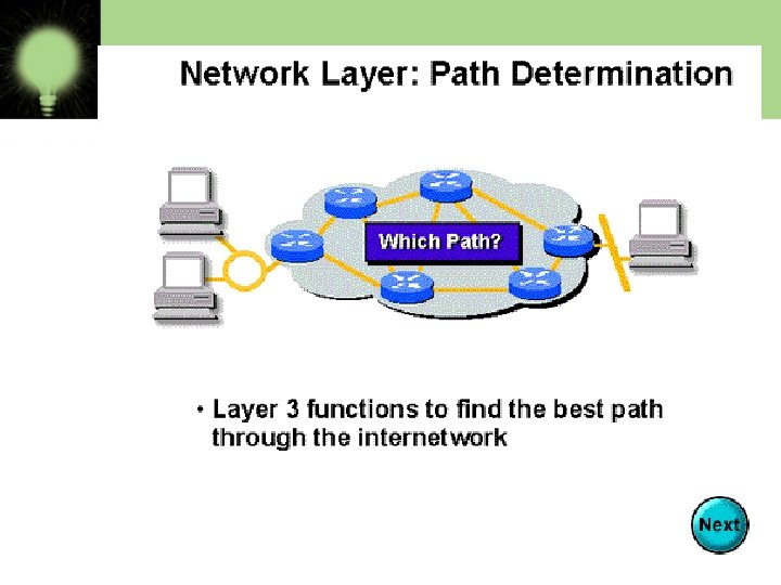
The Network Layer Ø The network layer of the OSI model, provides an end-to-end logical addressing system so that a packet of data can be routed across several layer 2 networks (Ethernet, Token Ring, Frame Relay, etc. ). Note that network layer addresses can also be referred to as logical addresses. Initially, software manufacturers, such as Novell, developed proprietary layer 3 addressing.
The Transport Layer Ø the transport layer of the OSI model, offers end-to-end communication between end devices through a network. Depending on the application, the transport layer either offers reliable, connection-oriented or connectionless, best-effort communications. Some of the functions offered by the transport layer include: Application identification • Client-side entity identification • Confirmation that the entire
The Session Layer Ø The session layer, provides various services, including tracking the number of bytes that each end of the session has acknowledged receiving from the other end of the session. This session layer allows applications functioning on devices to establish, manage, and terminate a dialog through a network. Session layer functionality includes: • Virtual connection between application entities • Synchronization of data flow • Creation of dialog units
The Presentation Layer Ø the presentation layer, is responsible for how an application formats the data to be sent out onto the network. The presentation layer basically allows an application to read (or understand) the message. Examples of presentation layer functionality include: • Encryption and decryption of a message for security • Compression and expansion of a message so that it travels efficiently • Graphics formatting • Content translation • System-specific translation www. globalknowledge. com
The Application Layer Ø the application layer, provides an interface for the end user operating a device connected to a network. This layer is what the user sees, in terms of loading an application (such as Web browser or e-mail); that is, this application layer is the data the user views while using these applications. Examples of application layer functionality include: • Support for file transfers • Ability to print on a network • Electronic mail
CHAPTER - 3 INTRODUCTION TO TCP/ IP
INTRODUCTION • TCP stands for transmission control protocol • IP stands for Internet Protocol.
TCP/IP OSI Model TCP/IP Hierarchy 7 th Application Layer 6 th Presentation Layer Application Layer 5 th Session Layer 4 th Transport Layer 3 rd Network Layer 2 nd Link Layer 1 st Physical Layer Link Layer Protocols
DESCRIPTION OF TCP/IP LAYER TCP/IP model has four layers: • HOST TO HOST NETWORK LAYER • INTERNET LAYER • TRANSPORT LAYER • APPLICATION LAYER
DIFFERENCE BETWEEN OSI AND TCP/IP • Key Differences between TCP/IP and OSI Model • TCP/IP is a client-server model, i. e. when the client requests for service it is provided by the server. Whereas, OSI is a conceptual model. • TCP/IP is a standard protocol used for every network including the Internet, whereas, OSI is not a protocol but a reference model used for understanding and designing the system architecture. • TCP/IP is a four layered model, whereas, OSI has seven layers. • TCP/IP follows Vertical approach. On the other hand, OSI Model supports Horizontal approach. • TCP/IP is Tangible, whereas, OSI is not. • TCP/IP follows top to bottom approach, whereas, OSI Model follows a bottom-up approach.
ADDRESSING • PHYSICAL ADDRESSING • LOGICAL ADDRESSING • IP ADDRESSING.
PHYSICAL ADDRESSING • The address assigned to a network interface card by the original manufaturer or by the network administrator is called physical address or hardware address.
TYPES OF PHYSICAL ADDRESSES • UNICAST ADDRESS • MULTICAST ADDRESS • BROADCAST ADDRESS
Description of physical address types: • UNICAST ADDRESS are permanently assigned to the network interface card(NIC) and are unique for machine. • MULICAST ADDRESSES are the addresses given to a group of hosts instead of single host. • BROADCAST ADDRESSES is an address, which if given in datagram, the message is communicated to all hosts in a network.
LOGICAL ADDRESSING • All logical address is the address which is allocated to an item and can be viewed from perspective of an application program
IP ADDRESSING The IP address format contains three fields: • Class Type • Network ID • Host ID
IP ADDRESS CLASSES
IP ADDRESS CLASSES • Class A: The first octet is the network portion. Octets 2, 3, and 4 are for subnets/hosts • Class B: The first two octets are the network portion. Octets 3 and 4 are for subnets/hosts
SUBNETTING IN IP �Creates multiple logical networks that exist within a single Class A, B, or C network. �If you do not subnet, you will only be able to use one network from your Class A, B, or C network, which is unrealistic �Each data link on a network must have a unique network ID, with every node on that link being a member of the same network
SUBNET MASK Determines the way an IP address is split into network and hosts portions Class A - 0 nnnnnnn. hhhhhhhh Subnet Mask = 255. 0. 0. 0 IP Address /8 Class B - 10 nnnnnn. hhhhhhhh Subnet Mask = 255. 0. 0 IP Address /16 Class C - 100 nnnnnnnn. hhhh Subnet Mask = 255. 0 IP Address /24
SUPERNETTING • It is the reverse concept of subnetting. It combines many networks in a region to form a single prefixed address.
IP PACKET FORMAT • The format used by the IP datagrams that carry the data messages in the network is called IP packet format. • An IP datagram consist of a header part and a text part.
NETWORK ARCHITECTURE
INTRODUCTION Network architecture is a set of layers and protocols to reduce the comprising. The data passes to the lowest layer by adding some control information. This is done till the last layer.
LOCAL AREA NETWORK(LAN) ETHERNET: Ethernet is a LAN architecture which was developed by Xerox. And extended by joint venture of DEC, IC and Xerox. It is specified by IEEE 802. 3 and it defines 2 categories, these categories are: Baseband Broadband
ELECTRICAL SPECIFICATIONS FOR ETHERNET Various electrical specification of Ethernet are as follows: 1. Signaling: Baseband system is used Manchester digital encoding while the broadband system use differential PSK. 2. Data rate: the Ethernet LANs support a data rate between one mbps to 100 mbps. Basebands define data rate of 1, 10 and 100 mbps while broadband defines a data rate of 10 m, bps. 3. Frame format: The IEEE 802. 3 specifies only one type of frame format that include 7 fields.
ETHERNET SPECIFICATIONS There are six Ethernet specifications as 10 base T, 10 base 5, 10 base 2, 1 base 5, 100 base T and 10 broad 36.
Ethernet Technologies: 10 Base 2 • • 10: 10 Mbps; 2: under 185 (~200) meters cable length Thin coaxial cable in a bus topology • Repeaters used to connect multiple segments – Repeater repeats bits it hears on one interface to its other interfaces: physical layer device only! CS 640 90
10 Base. T and 100 Base. T • 10/100 Mbps rate • T stands for Twisted Pair • Hub(s) connected by twisted pair facilitate “star topology” – Distance of any node to hub must be < 100 M CS 640 91
Switched Ethernet • Switches forward and filter frames based on LAN addresses – It’s not a bus or a router (although simple forwarding tables are maintained) • Very scalable – Options for many interfaces – Full duplex operation (send/receive frames simultaneously) • Connect two or more “segments” by copying data frames between them – Switches only copy data when needed • key difference from repeaters • Higher link bandwidth – Collisions are completely avoided • Much greater aggregate bandwidth – Separate segments can send at once CS 640 92
Physical Layer Configurations for 802. 3 • • Physical layer configurations are specified in three parts Data rate (10, 100, 1, 000) – 10, 100, 1, 000 Mbps • Signaling method (base, broad) – Baseband • Digital signaling – Broadband • Analog signaling • Cabling (2, 5, T, F, S, L) – – 5 - Thick coax (original Ethernet cabling) F – Optical fiber S – Short wave laser over multimode fiber L – Long wave laser over single mode fiber CS 640 93
Our Focus is Ethernet • History – – Developed by Bob Metcalfe and others at Xerox PARC in mid-1970 s Roots in Aloha packet-radio network Standardized by Xerox, DEC, and Intel in 1978 LAN standards define MAC and physical layer connectivity • IEEE 802. 3 (CSMA/CD - Ethernet) standard – originally 2 Mbps • IEEE 802. 3 u standard for 100 Mbps Ethernet • IEEE 802. 3 z standard for 1, 000 Mbps Ethernet • CSMA/CD: Ethernet’s Media Access Control (MAC) policy – CS = carrier sense • Send only if medium is idle – MA = multiple access – CD = collision detection • Stop sending immediately if collision is detected CS 640 94
State Diagram for CSMA/CD Pac ket? Sense Carrier No Send Detect Collision Yes Discard Packet attempts < 16 Jam channel b=Calc. Backoff(); wait(b); attempts++; attempts == 16 CS 640 95
Ethernet Standard Defines Physical Layer • 802. 3 standard defines physical layer details Metcalfe’s original Ethernet Sketch CS 640 96
Ethernet Problems • Ethernet’s peak utilization is pretty low (like Aloha) • Peak throughput worst with – More hosts • More collisions needed to identify single sender – Smaller packet sizes • More frequent arbitration – Longer links • Collisions take longer to observe, more wasted bandwidth – Efficiency is improved by avoiding these conditions CS 640 97
Ethernet Overview • Most popular packet-switched LAN technology • Bandwidths: 10 Mbps, 100 Mbps, 1 Gbps • Max bus length: 2500 m – 500 m segments with 4 repeaters • Bus and Star topologies are used to connect hosts – Hosts attach to network via Ethernet transceiver or hub or switch • Detects line state and sends/receives signals – Hubs are used to facilitate shared connections – All hosts on an Ethernet are competing for access to the medium • Switches break this model • Problem: Distributed algorithm that provides fair access CS 640 98
Ethernet Overview (contd. ) • Ethernet by definition is a broadcast protocol – Any signal can be received by all hosts – Switching enables individual hosts to communicate • Network layer packets are transmitted over an Ethernet by encapsulating • Frame Format 64 48 48 16 Preamble Dest addr Src addr Type CS 640 32 Body CRC 99
INTRODUCTION TO MEDIA CONNECTIVITY 1. VSAT(very small aperture terminal): It is two satellite ground station with dish antina that is smaller than 3 meters. Most VSAT antina range from 75 cm to 1. 2 m. CHARACTERISTIC: it uses *band c having frequency 3 to 7 GHz. The delivered power is low and rainfall effect is minimum. *band Ku having freq. 10 to 18 GHz. The delivered. power is medium and rainfall is medium.
2. PSTN(public switched telephone network): home telephone is connected to a circuit switch network via n exchange through a local loop. The two wire connections between each subscribers telephone and end office is known a local loop. 3. DSL(digital subscriber line): technology through which local loop telephone line of telecom network is used to accomplish high speed delivery of data. Data video voice and multimedia is called DSL. The link between subscriber and network is analog line.
3. OPTICAL FIBER: It is a medium to transmit data at high rates. Noise resistance high bandwidth. Expensive compared to other types of cable. 4. RF(RADIO FREQUENCY): RF can travel through air or space but require specific transmitting mechanism. It has frequency between 3 KHz to 300 GHz. 5. ISDN (integrated services digital network): ISDN was developed by ITU-T in 1976. It is set of protocols that combines digital telephony and data transport services.
K R O W T E S N E C I V E D
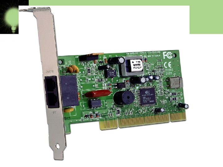
Modem • A modem is a computer peripheral that allows us to connect and communicate with other computers via telephone lines. In other words, Modem (Modulator-Demodulator) is a communication device that converts binary signal into analog signals (Modulation) for transmission over the telephone lines and converts these analog signals back into binary form ( Demodulation) at the receiving end.
WORKING OF MODEM DTE DCE TELEPHONE LINES MODEM DCE DTE
TWO BASIC PHYSICAL TYPES OF MODEM: 1. INTERNAL MODEM: Modems that are fixed within the computers. The advantage of an internal modem is the lack of extra wires required for installation. Internal modems get their power from the computer's power supply. 2. EXTERNAL MODEM: Modems connected externally to the computer. External modems require a power source and extra wires to connect to the computer. The advantage of external modems is that they feature lights on the front so you can monitor the connection status. Internal modems cannot be viewed from outside the computer except in the back of the unit.
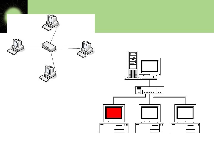
HUB A Hub is a hardware device used to connect several computers together. A hub contains multiple ports. FUNCTIONING OF A HUB: Hubs forward any data packets – including e-mail, word Hubs are either Passive or Active. documents, spreadsheets, ACTIVE HUBS: graphics- they receive over Electrically amplifies the signal as it moves from one port to all of the connected device to the other. remaining ports. All users PASSIVE HUBS: connected to a single hub are Allows the signal to pass from one computer to in the same segment. another without any change.
Networking Devices • Repeaters • Hubs • Multiplexers • Switches • Gate ways • NICs • Bridges www. csl. mtu. edu
SWITCH • A switch is a device that is used to segment networks into subnetworks called subnets. • Allow different nodes of a network to communicate directly with each other. • Allow several users to send information over a network at the same time without slowing each other down. • Responsible for filtering-transforms data in a specific way and forwarding packets between LAN segments.
REPEATER: What internetworking devices operate at the physical layer (layer 1) of the OSI model? • When signals first leave a transmitting station, they are clean and easily recognizable. However, the longer the cable length, the weaker and more deteriorated the signals become as they pass along the networking media. • Repeaters can be installed along the way to ensure that data packets reach destination
What is the disadvantage associated with using a repeater? • it can't filter network traffic. Data, sometimes referred to as bits, arriving at one port of a repeater gets sent out on all other ports • data gets passed along by a repeater to all other LAN segments of a network regardless of whether it needs to go there or not.
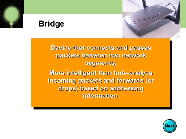
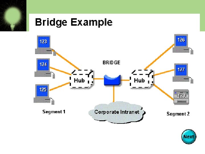
What internetworking device can be used to filter traffic on the network? • One way to solve the problems of too much traffic on a network and too many collisions is to use an internetworking device called a bridge. • A bridge eliminates unnecessary traffic and minimizes the chances of collisions occurring on a network by dividing it into segments
At what layer of the OSI model do bridges operate? • Because bridges operate at the data link layer, layer 2, they are not required to examine upper-layer information.
How are bridge data-forwarding decisions limited? • Although bridges use tables to determine whether or not to forward data to other segments of the network, the types of comparisons and decisions they make are relatively low level, simple ones www. csl. mtu. edu
What types of network traffic problems is a bridge incapable of solving? • Bridges work best where traffic from one segment of a network to other segments is not too great. • However, when traffic between network segments becomes too heavy, the bridge can become a bottleneck and actually slow down communication.
What are routers? • Routers are another type of internetworking device. • These devices pass data packets between networks based on network protocol or layer 3 information. • Routers have the ability to make intelligent decisions as to the best path for delivery of data on the network.
What network problems can routers help resolve? • The problem of excessive broadcast traffic can be solved by using a router. • Routers are able to do this, because they do not forward broadcast frames unless specifically told to do so
How do routers differ from bridges? • Routers differ from bridges in several respects. First, bridging occurs at the data link layer or layer 2, while routing occurs at the network layer or layer 3 of the OSI model. • Second, bridges use physical or MAC addresses to make data forwarding decisions. Routers use a different addressing scheme that occurs at layer three
How do routers work? • Routers are used to connect two or more networks. For routing to be successful, each network must have a unique network number www. csl. mtu. edu
gatewa. Y Device that connects dissimilar networks. Operates at the highest level of abstraction. Expands the functionality of routers by performing data translation and protocol conversion. Needed to convert Ethernet traffic from LAN to San(Systems Network Architecture)traffic legacy system. Then routes the SNA traffic to the mainframe. When Mainframe answers, Reverse process occurs. Establishes an intelligent connection between a local network and external networks with completely different structures.
Repeaters 5 -4 -3 Rule The maximum path between 2 stations on the network should not be more than 5 segments with 4 repeaters between those segments and no more than 3 populated segments. Repeaters Host A Host Z
Bridges are used to connect separate segments of a network. Bridges implement the Spanning-Tree Protocol to build a loop free network topology. This means that on a network , one or more bridges may be blocked if they are forming a loop. Bridges communicate with each other, exchanging information such as priority and bridge interface MAC address. They select a root bridge and then implement the Spanning-Tree Protocol. Blocking Bridges x Blocking x
Multiplexers • Multiplexing (and demultiplexing) allows for sending multiple signals through a single medium as well as for bidirectional use of that medium. • Time Division Multiplexing (TDM) • Wavelength-Division Multiplexing (WDM) • Frequency Division Multiplexing (FDM)
Multiplexing • Time-Division Multiplexing • Based on Time-Division Multiplexing • Wavelength-Division Multiplexing – Based on Frequency-Division Multiplexing of radio waves www. csl. mtu. edu
Time-Division Multiplexing – Transmitting digitized data over one medium • Wires or optical fibers • Pulses representing bits from different time slots – Two Types: • Synchronous TDM • Asynchronous TDM
• Synchronous TDM • Accepts input in a round-robin fashion • Transmits data in a never ending pattern • Popular – Line & Sources as much bandwidth Examples: – T-1 and ISDN telephone lines – SONET (Synchronous Optical NETwork)
• Asynchronous TDM • Accepts the incoming data streams and creates a frame containing only the data to be transmitted • Good for low bandwidth lines • Transmits only data from active workstations • Examples: – used for LANs
Time Division Multiplexing (TDM) • TDM is accomplished by creating phase delays each signal together but with differing phase delays
Frequency-Division Multiplexing (FDM) • All signals are sent simultaneously, each assigned its own frequency • Using filters all signals can be retrieved www. csl. mtu. edu
Wavelength-Division Multiplexing (WDM) • WDM is the combining of light by using different wavelengths
Basic Computer & Network Troubleshooting
TROUBLESHOOTING • Troubleshooting is a process of finding out the cause of problem and eliminating the problem by identifying the cause. • Troubleshooting steps: 1. Problem identification 2. Fault location 3. Fault removal
Computer Troubleshooting • Take a deep breath • Think it through • Take your time TLA
TROUBLE SHOOTING PROCESS • The problem identification is not a tough job. If you are careful about the network operations and regularly watch the system logs and routine operational procedures , then a little change may indicate that something is going wrong in the network. • The basic network problem include the following: 1. dialup networking problem 2. ISP problems 3. LAN problems 4. Fault finding 5. Fault isolations/locations
Approach -Emergency Repair Disk TLA 2003/Troubleshooting/Richard Wayne
Approach II- Updates TLA 2003/Troubleshooting/Richard
Troubleshooting • From www. webopedia. com - To isolate the source of a problem and fix it. In the case of computer systems, the term troubleshoot is usually used when the problem is suspected to be hardware related. If the problem is known to be in software, the term debug is more commonly used. TLA 2003/Troubleshooting/Richard 1 4
TROUBLESHOOTING TOOLS While working with network/internet many a times problems arises like, not able to connect to network. In such a case you need to resolve problem using troubleshooting tools of networking. some of them are described here: 1. Ping 2. Tracert/Traceroute 3. IPCONFIG/IFCONFIG 4. Netstat 5. Wiresharp 6. Sniffer(Packet sniffer)
1. PING: This is most commonly used tool. This tests connectivity between requesting hosts and destination hosts. 2. TRACERT: The traceroute command can be used to determine more specific information about the path to the destination hosts including the route the packet takes and the response time of these intermediate hosts. 3. IPCONFIG/IFCONFIG: this is used to determine IP configuration of host. It gives TCP/IP configuration details like IP address, subnet masks and default gateway for the computer. IPCONFIG is used for windows while IFCONFIG for linux machine. 4. NETSTAT: this is used to determine current state of active network connections on a host. It is important for various reasons.
5. WIRESHARK: Wireshark is a free open source packet analyzer used for troubleshooting network issues. 6. SNIFFER: Packet sniffer is used to look inside header of packets. It helps if packets, route and path are , as expected.
Give me a ping, Vasily. One ping only please!
Tracert
Computer Troubleshooting Finale • Keep your computers clean and updated • Use available resources • Ask “What changed? ”
WIRELESS NETWORKING Chapter 7
Wireless LAN A wireless LAN is defines as wireless local area network, which may be defined as connection of two or more computers without using wires. Wireless LANS connect computer networks via radio transmissions intead of traditional phone lines or cables
History of Wireless Network • It is an important form of connection in many business areas. • Earlier it was very expensive and used only in the places where cabling was difficult. • Now WLAN uses protocols like versions of IEEE 802. 11
WLAN/IEEE 802. 11 is a set of media access control (MAC) and physical layer (PHY) specifications for implementing wireless local area network (WLAN) computer communication in the 900 MHz and 2. 4, 3. 6, 5, and 60 GHz frequency bands. https: //en. wikipedia. org/wiki/IEEE_802. 11
IEEE 802. 11 Standards • 802. 11 — applies to wireless LANs and provides 1 or 2 Mbps transmission in the 2. 4 GHz band using either frequency hopping spread spectrum (FHSS) or direct sequence spread spectrum (DSSS). • 802. 11 a — an extension to 802. 11 that applies to wireless LANs and provides up to 54 -Mbps in the 5 GHz band. 802. 11 a uses an orthogonal frequency division multiplexing encoding scheme rather than FHSS or DSSS. • 802. 11 b (also referred to as 802. 11 High Rate or Wi-Fi) — an extension to 802. 11 that applies to wireless LANS and provides 11 Mbps transmission (with a fallback to 5. 5, 2 and 1 -Mbps) in the 2. 4 GHz band. 802. 11 b uses only DSSS. 802. 11 b was a 1999 ratification to the original 802. 11 standard, allowing wireless functionality comparable to Ethernet. • 802. 11 e — a wireless draft standard that defines the Quality of Service (Qo. S) support for LANs, and is an enhancement to the 802. 11 a and 802. 11 b wireless LAN (WLAN) specifications. 802. 11 e adds Qo. S features and multimedia support to the existing IEEE 802. 11 b and IEEE 802. 11 a wireless standards, while maintaining full backward compatibility with these standards. • 802. 11 g — applies to wireless LANs and is used for transmission over short distances at up to 54 -Mbps in the 2. 4 GHz bands. • 802. 11 n — 802. 11 n builds upon previous 802. 11 standards by adding multiple-input multiple-output(MIMO). The additional transmitter and receiver antennas allow for increased data throughput through spatial multiplexing and increased range by exploiting the spatial diversity through
IEEE 802. 11 Standards • 802. 11 ac — 802. 11 ac builds upon previous 802. 11 standards, particularly the 802. 11 n standard, to deliver data rates of 433 Mbps per spatial stream, or 1. 3 Gbps in a three-antenna (three stream) design. The 802. 11 ac specification operates only in the 5 GHz frequency range and features support for wider channels (80 MHz and 160 MHz) and beamforming capabilities by default to help achieve its higher wireless speeds. • 802. 11 ac Wave 2 — 802. 11 ac Wave 2 is an update for the original 802. 11 ac spec that uses MU-MIMOtechnology and other advancements to help increase theoretical maximum wireless speeds for the spec to 6. 93 Gbps. • 802. 11 ad — 802. 11 ad is a wireless specification under development that will operate in the 60 GHz frequency band offer much higher transfer rates than previous 802. 11 specs, with a theoretical maximum transfer rate of up to 7 Gbps (Gigabits per second). • 802. 11 ah— Also known as Wi-Fi Ha. Low, 802. 11 ah is the first Wi-Fi specification to operate in frequency bands below one gigahertz (900 MHz), and it has a range of nearly twice that of other Wi-Fi technologies. It's also able to penetrate walls and other barriers considerably better than previous Wi-Fi standards. • 802. 11 r - 802. 11 r, also called Fast Basic Service Set (BSS) Transition, supports Vo. Wi. Fi handoff between access points to enable Vo. IP roaming on a Wi-Fi network with 802. 1 X authentication. • 802. 1 X — Not to be confused with 802. 11 x (which is the term used to describe the family of 802. 11 standards) 802. 1 X is an IEEE standard for port-based Network Access Control that allows network administrators to restricted use of IEEE 802 LAN service access points to secure communication between authenticated and authorized devices. https: //www. webopedia. com/TERM/8/802_11. html
Wireless LAN Protocols • MACA, a wireless network node announces that it is going to send the data frame, informing the other nodes to remain silent. When a node intends to transmit the data frame, it communicates using a signal known as Request-To-Send (RTS) that includes the length of the data frame to transmit. If the recipient permits the transmission, it responds back to the sender with a signal known as Clear-To-Send (CTS), which includes the length of the data frame that it is about to receive. • In the meantime, the nodes that listen to the RTS signal must remain silent until the data is fully transmitted in order to avoid conflict with CTS. Collisions among RTS packets may still occur in MACA, but they are minimized using a randomized exponential back-off strategy, much like the one that is used in regular Carrier Sense Multiple Access (CSMA).
Wireless LAN Protocols • Although collisions can occur between RTS packets, MACA still has an edge over CSMA, provided that the RTS packets are substantially smaller compared to the data packets. If the RTS packets are significantly smaller, the collisions between RTS packets create less impact. • WLAN data transmission collisions can still happen, and MACA for Wireless (MACAW) is brought to extend the functionality of MACA. It demands nodes to send acknowledgments after every successful frame transmission. MACAW is commonly used in ad hoc networks. Moreover, it is the basis of various other MAC protocols found in wireless sensor networks (WSN). https: //www. techopedia. com/
Benefites of Wireless LAN • Mobility enables users to physically move while using an appliance, such as a handheld PC or data collector. Many jobs require workers to be mobile—these include inventory clerks, healthcare workers, policemen, and emergency care specialists. Of course, wireline networks require a physical tether between the user's workstation and the network's resources, which makes access to these resources impossible while roaming about the building or elsewhere. This freedom of movement
Benefites of Wireless LAN • Installation in Difficult-to-Wire Areas The implementation of wireless networks offers many tangible cost savings when performing installations in difficult-to-wire areas. If rivers, freeways, or other obstacles separate buildings that you want to connect, a wireless solution may be much more economical than installing physical cable or leasing communications circuits, such as T 1 service or 56 Kbps lines. Some organizations spend thousands or even millions of dollars to install physical links with nearby facilities. If you are facing this type of installation, consider wireless networking as an alternative. The deployment of wireless networking in these situations costs thousands of dollars but will result
Benefites of Wireless LAN • Increased Reliability An advantage of wireless networking, therefore, results from the use of less cable. This reduces the downtime of the network and the costs associated with replacing cables.
Benefites of Wireless LAN Reduced Installation Time • The installation of cabling is often a timeconsuming activity. For LANs, installers must pull twisted-pair wires above the ceiling and drop cables through walls to network outlets that they must affix to the wall. These tasks can take days or weeks, depending on the size of the installation. The installation of optical fiber between buildings within the same geographical area consists of digging trenches to lay the fiber or pulling the fiber through an existing conduit. You might need weeks or possibly months to receive right-of-way approvals and dig through ground asphalt. • The deployment of wireless networks greatly
Benefits of Wireless LAN • Long-Term Cost Savings http: //www. informit. com/articles/
Architecture of Wireless LAN • IEEE 802. 11 Architecture • The smallest building block of a wireless LAN is a basic service set (BSS), which consists of some number of stations executing the same MAC protocol and competing for access to the same shared wireless medium. • A BSS may isolated or it may connect to a backbone distribution system (DS) through an access point (AP). • The AP functions as a bridge and a relay point. In a BSS, client stations do not communicate directly with one another. • Rather, if one station in the BSS wants to communicate with another station in the same BSS, the MAC frame first sent from the originating station to the AP, and then from the AP to the destination station. • Similarly, a MAC frame from a station in the BSS to a remote station sent from the local station to the AP and then relayed by the AP over the DS on its way to the destination station. • The BSS generally corresponds to what referred to as a cell in the literature. The DS can a switch, a wired network, or a wireless network. • When all the stations in the BSS mobile stations, with no connection to other BSSs, the BSS called an independent BSS (IBSS).
• A simple configuration is shown in Figure, in which each station belongs to a single BSS; that is, each station is within wireless range only of other stations within the same BSS. • It is also possible for two BSSs to overlap geographically so that a single station could participate in more than one BSS. • Further, the association between a station and a BSS dynamic. Stations may turn off, come within range, and go out of range. • An extended service set (ESS) consists of two or more basic service sets interconnected by a distribution system. • Typically, the distribution system a wired backbone LAN but can any communications network. • The extended service set appears as a single logical LAN to the logical link control (LLC) level. • The figure indicates that an access point (AP) implemented as part of a station; the AP the logic within a station that provides access to the DS by providing DS services in addition to acting as a station. • To integrate the IEEE 802. 11 architecture with a traditional wired LAN, a portal used. The portal logic implemented in a device, such as a bridge or a router. That part of the wired LAN and that attached to the DS.
Architecture of Wireless LAN
Components of Architecture • Stations All components that can connect into a wireless medium in a network are referred to as stations (STA). All stations are equipped with wireless network interface controllers (WNICs). Wireless stations fall into two categories: wireless access points, and clients. Access points (APs), normally wireless routers, are base stations for the wireless network. They transmit and receive radio frequencies for wireless enabled devices to communicate with. Wireless clients can be mobile devices such as laptops, personal digital assistants, IP phones and other smartphones, or nonportable devices such as desktop computers, printers, and workstations that are equipped with a wireless network interface. • Basic service set The basic service set (BSS) is a set of all stations that can communicate with each other at PHY layer. Every BSS has an identification (ID) called the BSSID, which is the MAC address of the access point servicing the BSS. There are two types of BSS: Independent BSS (also referred to as IBSS), and infrastructure BSS. An independent BSS (IBSS) is an ad hoc network that contains no access points, which means they cannot connect to any other basic service set.
Components of Architecture • Basic service set • The basic service set (BSS) is a set of all stations that can communicate with each other at PHY layer. Every BSS has an identification (ID) called the BSSID, which is the MAC address of the access point servicing the BSS. • There are two types of BSS: Independent BSS (also referred to as IBSS), and infrastructure BSS. An independent BSS (IBSS) is an ad hoc network that contains no access points, which means they cannot connect to any other basic service set. • Independent basic service set • An IBSS is a set of STAs configured in ad hoc (peer-to-peer)mode. • Extended service set • An extended service set (ESS) is a set of connected BSSs. Access points in an ESS are connected by a distribution system. Each ESS has an ID called the SSID which is a 32 byte (maximum) character string. • Distribution system • A distribution system (DS) connects access points in an extended service set. The concept of a DS can be used to increase network coverage through roaming between cells. • DS can be wired or wireless. Current wireless distribution systems are mostly based on WDS or MESH protocols, though other systems are in use.
Bluetooth Fundamentals • Universal short-range wireless capability • Uses 2. 4 -GHz band • Available globally for unlicensed users • • Devices within 10 m can share up to 720 kbps of capacity Supports open-ended list of applications • Data, audio, graphics, video
Architecture of Bluetooth • Piconet – – – • Basic unit of Bluetooth networking Master and one to seven slave devices Master determines channel and phase Scatternet – – Device in one piconet may exist as master or slave in another piconet Allows many devices to share same area Makes efficient use of bandwidth Not implemented in COTS equipment
Applications of Bluetooth • Data and voice access points • • Cable replacement • • Real-time voice and data transmissions Eliminates need for numerous attachments for connection cable Ad hoc networking • Device with Bluetooth radio can establish connection with another when in range https: //learn. sparkfun. com/tutorials/bluetooth- basics
Bluetooth Protocol Stack
Difference in Bluetooth and Wi-Fi The main difference is that Bluetooth is primarily used to connect devices without using cables, while Wi-Fi provides highspeed access to the internet. Bluetooth is a wireless technology standard that is used to exchange data over short distances (less than 30 feet), usually between personal mobile devices.
New in Bluetooth • Atomic Encryption Change • Extended Enquiry Response • Sniff Rub Rating • Improvements in Quality of Services • Simple Pairing
Bluetooth Security Bluetooth uses the safer algorithm for authentication and key generation. The EO stream cipher is used for encrypting packets. This makes eavesdropping on Bluetooth enabled devices more difficult for certain classes of devices such as Handheld phones. It uses stronger and asymmetric key establishment methods.