Network Layer Controldata plane addressing routers CS 352


 Class 32 bits A 0 Net Type of Serv.")


 Assume IP addresses A and B share subnet mask M. Are")


 line termination •")


")
 “type” of data max")
 - largest")


 • Provides delivery of packets from one host to any")
- Slides: 45
Network Layer: Control/data plane, addressing, routers CS 352, Lecture 10 http: //www. cs. rutgers. edu/~sn 624/352 -S 19 Srinivas Narayana (heavily adapted from slides by Prof. Badri Nath and the textbook authors) 1
Next: Network layer Application Transport HTTPS FTP HTTP DNS UDP TCP IP Network Host-to-Net SMTP 802. 11 X. 25 … ATM
Network layer • transport segment from sending to receiving host • on sending side encapsulates segments into datagrams • on receiving side, delivers segments to transport layer • network layer protocols in every host, router • router examines header fields in all IP datagrams passing through it application transport network data link physical network data link physical network data link physical application transport network data link physical 3
Two key network-layer functions: • forwarding: move packets from router’s input to appropriate router output • routing: determine route taken by packets from source to destination analogy: taking a trip § forwarding: process of getting through single interchange § routing: process of planning trip from source to destination • routing algorithms 4
Network layer: data plane, control plane Data plane Control plane § local, per-router function § determines how datagram arriving on router input port is forwarded to router output port § forwarding function § network-wide logic § determines how datagram is routed among routers along end-end path from source host to destination host § two control-plane approaches: • traditional routing algorithms: implemented in routers • software-defined networking (SDN): implemented in (remote) servers values in arriving packet header 1 0111 3 2 5
IP Addressing
IPv 4 Addresses • 32 bits long • Identifier for host, router interface • Notation: • Each byte is written in decimal in MSB order, separated by dots • Example: 128. 195. 1. 80 stands for the 32 -bit IP address 10000000 11000011 00000001 01010000 7
Types of IPv 4 Addresses • Unicast Address • Destination is a single host • Multicast address • Destination is a group of hosts • Broadcast address • 255 • Destination is all hosts 8
IPv 4 Address Classes (old) Class 32 bits A 0 Net Type of Serv. Host B 10 C 110 D 1110 Multicast address E 1111 Reserved Net Host 9
IP Address Classes • Class A: • • For very large organizations 16 million hosts allowed • Class B: • • For large organizations 65 thousand hosts allowed • Class C • • For small organizations 255 hosts allowed • Class D • • Multicast addresses No network/host hierarchy 10
Problems with Class-based Routing • Too many small networks requiring multiple class C addresses • Running out of class B addresses, not enough nets in class A • Addressing strategy must allow for greater diversity of network sizes 11
IP addressing: CIDR: Classless Inter. Domain Routing • subnet portion of address of arbitrary length • address format: a. b. c. d/x, where x is # bits in subnet portion of address subnet part host part 11001000 00010111 00010000 200. 23. 16. 0/23 12
CIDR • An ISP can obtain a block of addresses and partition this further to its customers • Say an ISP has 200. 8. 0. 0/16 address (65 K addresses). • He has another customer who needs only 64 addresses starting from 200. 8. 4. 128 • Then that block can be specified as 200. 8. 4. 128/26 13
Subnetting Example: Class B address with 8 -bit subnetting Example Address: 16 bits Network id 8 bits Subnet id 165. 230 . 24 8 bits Host id. 8 14
Subnet Masks Subnet masks allow hosts to determine if another IP address is on the same subnet or the same network Mask: 16 bits Network id 8 bits Subnet id 8 bits Host id 11111111 0000 . 255 . 0 255 15
Subnet Masks (cont’d) Assume IP addresses A and B share subnet mask M. Are IP addresses A and B on the same subnet? 1. Compute logical AND (A & M). 2. Compute logical AND (B & M). 3. If (A & M) == (B & M) then A and B are on the same subnet. Example: A and B are class B addresses A = 165. 230. 82. 52 Same (classful) network? B = 165. 230. 24. 93 Same subnet? M = 255. 0 16
Example of IP Addressing in a network 223. 1. 1. 1 223. 1. 1. 2 223. 1. 1. 4 223. 1. 1. 3 223. 1. 2. 9 223. 1. 3. 27 223. 1. 2. 2 223. 1. 3. 2 17
What’s inside a router?
What do routers look like? Access routers Core router Data center top-of-rack switch 19
Basic components: Control & Data Planes Traditionally: Control plane per route-change processing (~ a few seconds) Routing Algorithm control plane data plane Data plane per-packet processing (~ tens of nanoseconds) 0111 values in arriving packet header Individual routing algorithm components in each and every router interact in the control plane 1 3 2 20
Router architecture overview routing processor Control plane Data plane high-speed switching fabric router input ports router output ports
Input port functions line termination physical layer: bit-level reception data link layer: e. g. , Ethernet (We’ll see this later in the course) link layer protocol (receive) lookup, forwarding switch fabric queueing Switching: • using header field values, lookup output port using forwarding table in input port memory (“match plus action”) • goal: complete input port processing at ‘line speed’ • queuing: if datagrams arrive faster than forwarding rate into switch fabric
Destination-based Forwarding in the Internet Packet payload header Router Destination Address Routing Lookup Data Structure Outgoing Port Forwarding Table Dest-network Port 65. 0. 0. 0/8 3 128. 9. 0. 0/16 1 149. 12. 0. 0/19 7 23
Three types of switching fabrics
Output Ports switch fabric datagram buffer queueing link layer protocol (send) line termination • Buffering required when datagrams arrive from fabric faster than the transmission rate • Important implication: if buffers filled up, packets are dropped! • Scheduling discipline chooses among queued datagrams for transmission • Important implication: Who gets priority is chosen by the scheduler 25
Prefixes and IP lookup
Example Forwarding Table Destination IP Prefix Outgoing Port 65. 0. 0. 0/8 3 Prefix length 128. 9. 0. 0/16 1 65. 0. 0. 128/25 4 142. 12. 0. 0/19 7 IP prefix: 0 -32 bits Longest prefix match 65. 0. 0. 0/8 0 65. 0. 0. 0 128. 9. 0. 0/16 128. 9. 16. 14 224 65. 255 142. 12. 0. 0/19 232 -1 27
Prefixes can Overlap Longest matching prefix 128. 9. 176. 0/24 128. 9. 16. 0/24 65. 0. 0. 0/8 0 128. 9. 0. 0/16 128. 9. 16. 14 142. 12. 0. 0/19 232 -1 Routing lookup: Find the longest matching prefix (the most specific route) among all prefixes that match the destination address. 28
Reducing Routing Table Size Without CIDR: 200. 71. 0. 0 200. 71. 1. 0 200. 71. 2. 0 …. . 200. 71. 255. 0 service provider 200. 71. 0. 0 200. 71. 1. 0 200. 71. 2. 0 …. . 200. 71. 255. 0 Routing table With CIDR: 200. 71. 0. 0 200. 71. 1. 0 200. 71. 2. 0 …. . 200. 71. 255. 0 service provider 200. 71. 0. 0/16 Routing table 29
Hierarchical addressing: Route aggregation Efficient advertisement of routing information! Organization 0 200. 23. 16. 0/23 Organization 1 200. 23. 18. 0/23 Organization 2 200. 23. 20. 0/23 Organization 7 . . . Fly-By-Night-ISP “Send me anything with addresses beginning 200. 23. 16. 0/20” Internet 200. 23. 30. 0/23 ISPs-R-Us “Send me anything with addresses beginning 199. 31. 0. 0/16” 30
LPM: Announcing more specific routes ISPs-R-Us has a more specific route to Organization 1 Longest prefix match will be used to route IP packets Organization 0 200. 23. 16. 0/23 Organization 2 200. 23. 20. 0/23 Organization 7 . . . Fly-By-Night-ISP “Send me anything with addresses beginning 200. 23. 16. 0/20” Internet 200. 23. 30. 0/23 ISPs-R-Us Organization 1 200. 23. 18. 0/23 “Send me anything with addresses beginning 199. 31. 0. 0/16 or 200. 23. 18. 0/23” 31
The Internet Protocol (IP)
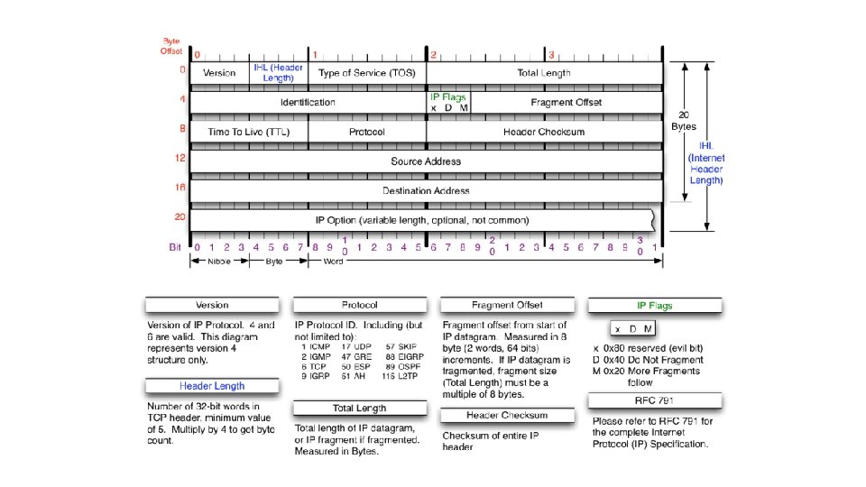
IP datagram format IP protocol version number header length (bytes) “type” of data max number remaining hops (decremented at each router) upper layer protocol to deliver payload to how much overhead with TCP? q 20 bytes of TCP q 20 bytes of IP q = 40 bytes + app layer overhead 32 bits ver head. type of len service 16 -bit identifier upper time to layer live length fragment flgs offset header checksum total datagram length (bytes) for fragmentation/ reassembly 32 bit source IP address 32 bit destination IP address Options (if any) data (variable length, typically a TCP or UDP segment) E. g. timestamp, record route taken, specify list of routers to visit. 33
IP Fragmentation & Reassembly • network links have MTU (max. transfer size) - largest possible link-level frame. • different link types, different MTUs • large IP datagram divided (“fragmented”) within net • one datagram becomes several datagrams • “reassembled” only at final destination • IP header bits used to identify, order related fragments fragmentation: in: one large datagram out: 3 smaller datagrams reassembly 34
IP Fragmentation and Reassembly Example q 4000 byte datagram q MTU = 1500 bytes 1480 bytes in data field offset = 1480/8 length ID fragflag =4000 =x =0 offset =0 One large datagram becomes several smaller datagrams length ID fragflag =1500 =x =1 offset =0 length ID fragflag =1500 =x =1 offset =185 length ID fragflag =1040 =x =0 offset =370 35
IP Address Hierarchy • Class A, B, C addresses support two levels of hierarchy • However, the host portion can be further split into “subnets” by the address class owner • more than 2 levels of hierarchy 38
Basic Components Routing Protocols Routing Table Control Plane Data plane Forwarding Switching Table per-packet processing 39
Router Architecture Overview 40
Input Port Functions Physical layer: bit-level reception Data link layer: e. g. , Ethernet see chapter 5 Decentralized switching: • queuing: if datagrams arrive faster than forwarding rate into switch fabric 41
Three types of switching fabrics 42
Longest prefix match • With CIDR, route entries are prefixes <prefix, CIDR mask> • Can be aggregated • We need to find the longest matching prefix that matches the destination address • Need to search all prefixes of all length (in order) and among prefixes of the same length 128. 8. 2/24 128. 8. 0/16 128. 8. 0. 24 192. 2. 0/16 128. 8. 2. 128 192. 2. 2. 128 43
The Internet Protocol (IP) • Provides delivery of packets from one host to any other host in the Internet • Internet packets are called “datagrams” and may be up to 64 kilobytes in length • although they are typically much smaller 45