
NESC Academy Webcast Autonomous Navigation For Deep Space
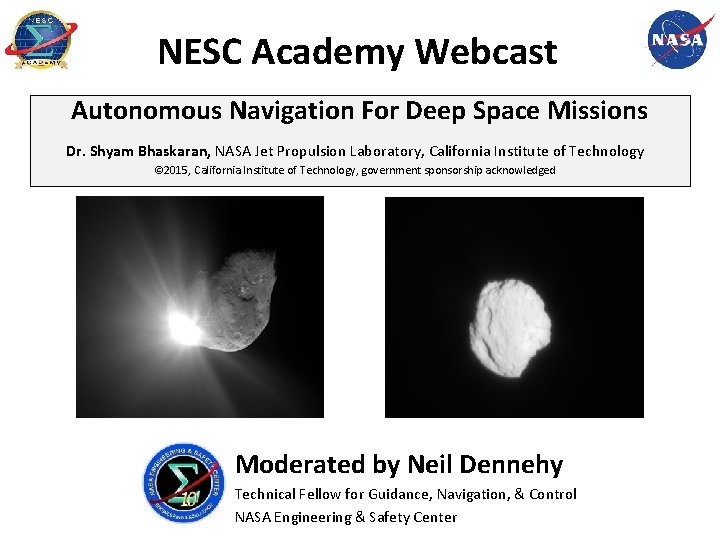
NESC Academy Webcast Autonomous Navigation For Deep Space Missions Dr. Shyam Bhaskaran, NASA Jet Propulsion Laboratory, California Institute of Technology © 2015, California Institute of Technology, government sponsorship acknowledged Moderated by Neil Dennehy Technical Fellow for Guidance, Navigation, & Control NASA Engineering & Safety Center
Agenda • • • Brief introduction to deep space navigation Brief introduction to optical navigation Overview of Autonomous Navigation (Auto. Nav) Examples of Auto. Nav use Some thoughts on enhancements and future uses of Auto. Nav September 23, 2015 2
Background on Deep Space Navigation • Spacecraft have visited 8 planets, 3 dwarf planets (Vesta, Ceres, Pluto), asteroids and comets • Navigation (determining where the spacecraft is at any given time, controlling its path to achieve desired targets), performed using ground-in -the-loop techniques. • Data for orbit determination includes a combination of: – 2 -way Doppler, which measures line-of-sight velocity from spacecraft to tracking station – 2 -way range, which measures line-of-sight range from spacecraft to tracking station – Delta-Differential One-way Range (Delta-DOR), which provides plane-of-sky angular measurement – Optical images of natural bodies taken by onboard camera (Op. Nav), which measures angle between spacecraft and body against an inertial reference September 23, 2015 3
Background on Deep Space Navigation • Data received and processed on the ground • Orbit determination (OD) computed using linearized least squares filter – Observed tracking data are differenced with predicted values based on reference trajectory (residuals) – Adjust parameters of orbit (position, velocity, other constants) using least squares to minimize sum-of-squares of residuals until convergence • At desired times, maneuvers are computed to correct trajectory errors, and commands sent to execute maneuvers on spacecraft • For deep space, data are received using one of three Deep Space Network complexes (Goldstone, CA, Canberra, Australia, and Madrid, Spain) – DSN is a heavily used resource • Current capabilities can achieve highly accurate results, for example: – km level targeting accuracies for satellite flybys on Cassini mission – 10 s of km landing ellipses on Mars • Still need to keep increasing performance for future missions, and alleviate pressure on DSN use. September 23, 2015 4
Drawbacks to Ground-based Navigation • Long round-trip light time (many minutes to many hours), depending on where the spacecraft is in Solar System • Time needed to process the data by analysts – – Orbit determination and maneuver calculations Analyze results Convene meetings to make decisions and implement decisions Generate sequence commands and uplink them to spacecraft • Lag time between the last navigation update and implementing maneuvers can typically take 8 or more hours to over a week. As a result: – Loss of some science, for example, to precisely point instruments at a target cannot use latest navigation knowledge – Loss for mission parameters, such as increased use of fuel as the orbit information has become stale during turnaround time to implement maneuvers September 23, 2015 5
Onboard Autonomous Navigation • A self-contained, onboard, autonomous navigation system can: – – Eliminate delays due to round-trip light time Eliminate the human factors in ground-based processing Reduce turnaround time from navigation update to minutes, down to seconds React to late-breaking data • A framework and computational elements of an autonomous navigation system has been developed, called Auto. Nav – Originally developed as one of the technologies for the Deep Space 1 mission, launched in 1998 – Subsequently used on three other spacecraft, for four different missions – Primary use has been on comet missions to track comets during flybys, and impact one comet September 23, 2015 6
Auto. Nav Data • • In principle, can use same data as ground-based navigation (radiometric and optical) – Radiometric data requires other information, such as media calibrations, for Earth-based data, or location of other spacecraft for spacecraft-to-spacecraft data More straightforward to use entirely self-contained data, so current Auto. Nav based on using optical data only (Op. Nav) – Passive optical data uses onboard camera to image celestial bodies – Bodies can be distant point sources (“unresolved”), distant resolved bodies, or bodies which partially or completely fill the camera FOV, in which case terrain-relative navigation techniques can be employed – Raw images reduced to sample/line coordinates of sub-pixel centers of stars and target object (“centerfinding”) September 23, 2015 7
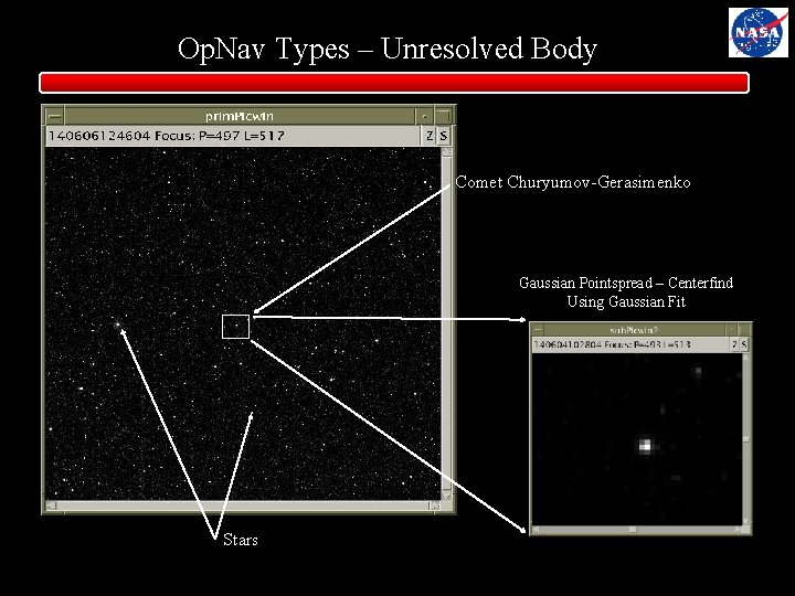
Op. Nav Types – Unresolved Body Comet Churyumov-Gerasimenko Gaussian Pointspread – Centerfind Using Gaussian Fit Stars September 23, 2015 8
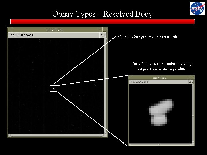
Opnav Types – Resolved Body Comet Churyumov-Gerasimenko For unknown shape, centerfind using brightness moment algorithm September 23, 2015 9
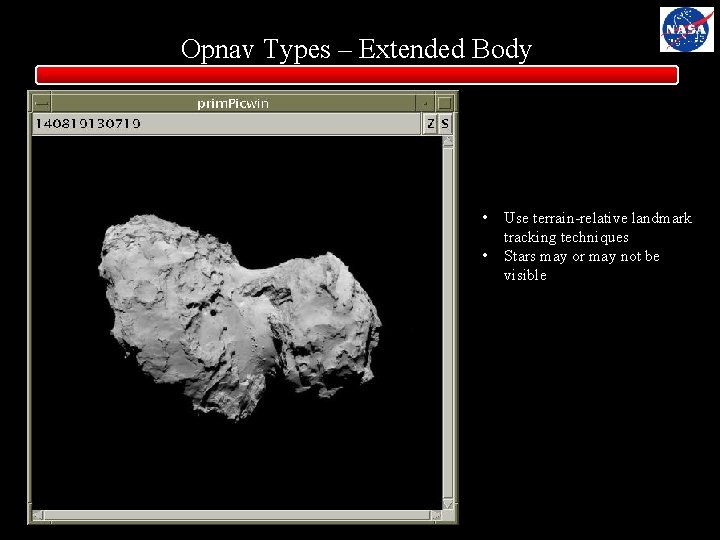
Opnav Types – Extended Body • • Use terrain-relative landmark tracking techniques Stars may or may not be visible September 23, 2015 10
Op. Nav Basics • Op. Nav works on the basis of parallax • Apparent shift of body in camera FOV from its predicted location to where it actually is can be due to one of two things – Either the body or the spacecraft is not where it was predicted to be – The direction the camera was pointing was not where it was predicted to be • We can eliminate the 2 nd source *if* there are stars in the camera FOV – Stars are, for all practical purposes, at an infinite distance, so there is no discernible parallax due caused by the star or spacecraft position – Can use stars in FOV to adjust the inertial pointing knowledge to eliminate it as a source of error • 1 star – can solve for Right Ascension and Declination of pointing • 2 or more stars – can also solve for the “twist” – rotation around camera boresight – Refer to this as “stellar referenced” Op. Nav • If stars are not available, then the RA/DEC/TWIST parameter must also be solved for in the filter, degrading the accuracy of the solution September 23, 2015 11
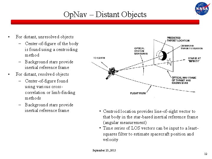
Op. Nav – Distant Objects • • For distant, unresolved objects – Center-of-figure of the body is found using a centroiding method – Background stars provide inertial reference frame For distant, resolved objects – Center-of-figure found using various crosscorrelation or limb-finding methods – Background stars provide inertial reference frame • Centroid location provides line-of-sight vector to that body in the star-based inertial reference frame (angular measurement) • Time series of LOS vectors can be input to a leastsquares filter to estimate spacecraft position and velocity September 23, 2015 12
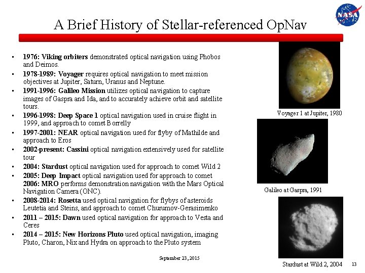
A Brief History of Stellar-referenced Op. Nav • • • 1976: Viking orbiters demonstrated optical navigation using Phobos and Deimos. 1978 -1989: Voyager requires optical navigation to meet mission objectives at Jupiter, Saturn, Uranus and Neptune. 1991 -1996: Galileo Mission utilizes optical navigation to capture images of Gaspra and Ida, and to accurately achieve orbit and satellite tours. 1996 -1998: Deep Space 1 optical navigation used in cruise flight in 1999, and approach to comet Borrelly 1997 -2001: NEAR optical navigation used for flyby of Mathilde and approach to Eros 2002 -present: Cassini optical navigation extensively used for satellite tour 2004: Stardust optical navigation used for approach to comet Wild 2 2005: Deep Impact optical navigation used for approach to comet 2006: MRO performs demonstration navigation with the Mars Optical Navigation Camera (ONC). 2008 -2014: Rosetta used optical navigation for flybys of asteroids Leutetia and Steins, and approach to comet Churumov-Gerasimenko 2011 – 2015: Dawn used optical navigation for approach to Vesta and Ceres 2014 – 2015: New Horizons Pluto used optical navigation, imaging Pluto, Charon, Nix and Hydra on approach to the Pluto system Voyager 1 at Jupiter, 1980 Galileo at Gaspra, 1991 September 23, 2015 Stardust at Wild 2, 2004 13
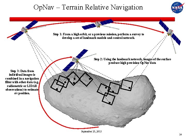
Op. Nav – Terrain Relative Navigation Step 1: From a high orbit, or a previous mission, perform a survey to develop a set of landmark models and control network. Step 2: Using the landmark network, images of the surface produce high precision Op. Nav data Step 3: Data from individual images is combined in a navigation filter with other data (e. g. radiometric or LIDAR observations) to estimate s/c position. September 23, 2015 14
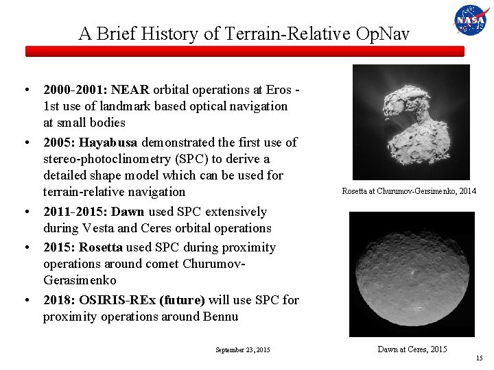
A Brief History of Terrain-Relative Op. Nav • 2000 -2001: NEAR orbital operations at Eros 1 st use of landmark based optical navigation at small bodies • 2005: Hayabusa demonstrated the first use of stereo-photoclinometry (SPC) to derive a detailed shape model which can be used for terrain-relative navigation • 2011 -2015: Dawn used SPC extensively during Vesta and Ceres orbital operations • 2015: Rosetta used SPC during proximity operations around comet Churumov. Gerasimenko • 2018: OSIRIS-REx (future) will use SPC for proximity operations around Bennu September 23, 2015 Rosetta at Churumov-Gersimenko, 2014 Dawn at Ceres, 2015 15
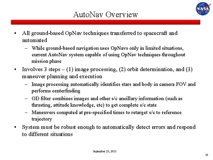
Auto. Nav Overview • All ground-based Op. Nav techniques transferred to spacecraft and automated – While ground-based navigation uses Op. Navs only in limited situations, current Auto. Nav system capable of using Op. Nav techniques throughout mission phase • Involves 3 steps – (1) image processing, (2) orbit determination, and (3) maneuver planning and execution – Image processing automatically identifies stars and body in camera FOV and performs centerfinding – OD filter combines images and other s/c ancillary information (such as thrusting, attitude knowledge, etc) to get complete s/c state – Maneuvers computed at pre-specified times to retarget s/c to reference trajectory • System must be robust enough to automatically detect errors and respond to different situations September 23, 2015 16
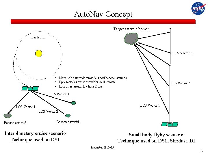
Auto. Nav Concept Target asteroid/comet Earth orbit LOS Vector n • Main belt asteroids provide good beacon sources • Ephemerides are reasonably well known • Lots of asteroids to chose from LOS Vector 2 LOS Vector 3 LOS Vector 1 LOS Vector 2 Beacon asteroid Interplanetary cruise scenario Technique used on DS 1 Small body flyby scenario Technique used on DS 1, Stardust, DI September 23, 2015 17
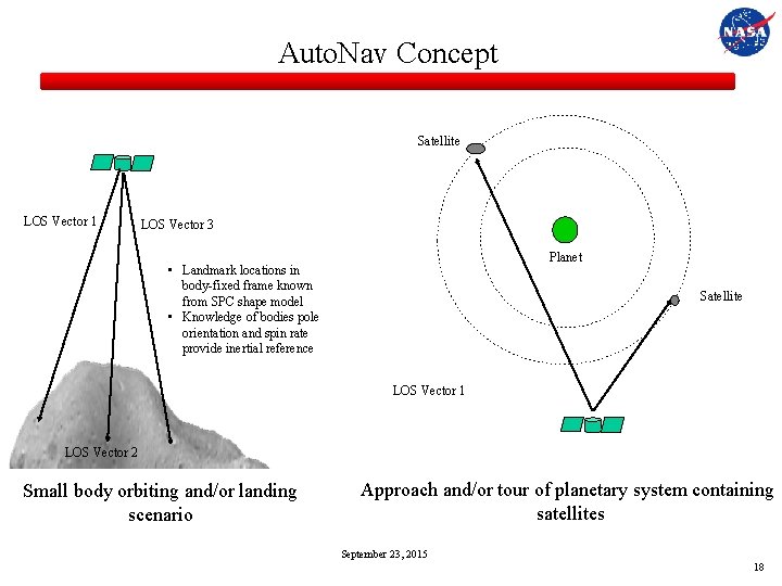
Auto. Nav Concept Satellite LOS Vector 1 LOS Vector 3 Planet • Landmark locations in body-fixed frame known from SPC shape model • Knowledge of bodies pole orientation and spin rate provide inertial reference Satellite LOS Vector 1 LOS Vector 2 Small body orbiting and/or landing scenario Approach and/or tour of planetary system containing satellites September 23, 2015 18
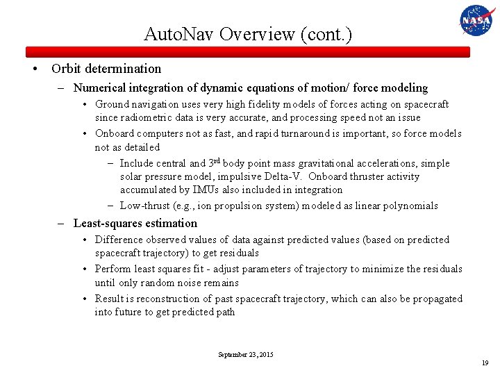
Auto. Nav Overview (cont. ) • Orbit determination – Numerical integration of dynamic equations of motion/ force modeling • Ground navigation uses very high fidelity models of forces acting on spacecraft since radiometric data is very accurate, and processing speed not an issue • Onboard computers not as fast, and rapid turnaround is important, so force models not as detailed – Include central and 3 rd body point mass gravitational accelerations, simple solar pressure model, impulsive Delta-V. Onboard thruster activity accumulated by IMUs also included in integration – Low-thrust (e. g. , ion propulsion system) modeled as linear polynomials – Least-squares estimation • Difference observed values of data against predicted values (based on predicted spacecraft trajectory) to get residuals • Perform least squares fit - adjust parameters of trajectory to minimize the residuals until only random noise remains • Result is reconstruction of past spacecraft trajectory, which can also be propagated into future to get predicted path September 23, 2015 19
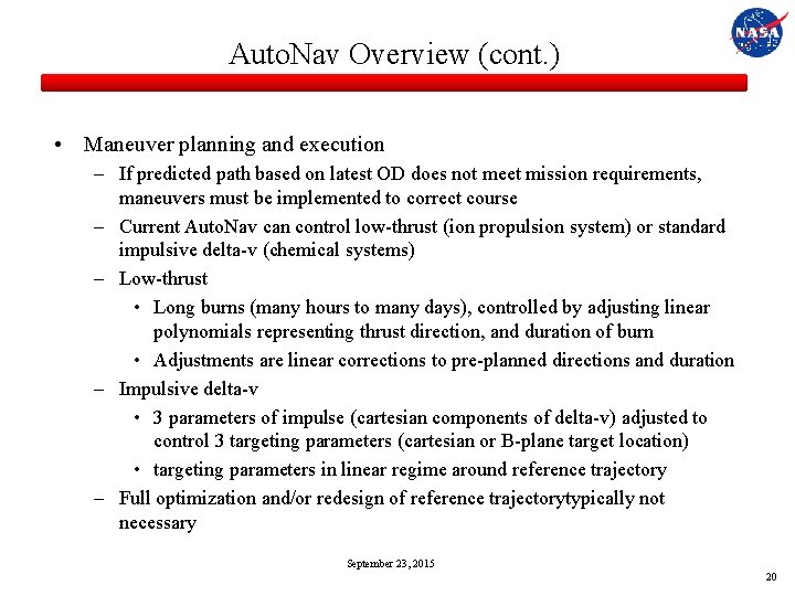
Auto. Nav Overview (cont. ) • Maneuver planning and execution – If predicted path based on latest OD does not meet mission requirements, maneuvers must be implemented to correct course – Current Auto. Nav can control low-thrust (ion propulsion system) or standard impulsive delta-v (chemical systems) – Low-thrust • Long burns (many hours to many days), controlled by adjusting linear polynomials representing thrust direction, and duration of burn • Adjustments are linear corrections to pre-planned directions and duration – Impulsive delta-v • 3 parameters of impulse (cartesian components of delta-v) adjusted to control 3 targeting parameters (cartesian or B-plane target location) • targeting parameters in linear regime around reference trajectory – Full optimization and/or redesign of reference trajectorytypically not necessary September 23, 2015 20
Auto. Nav Overview (cont. ) • Data editing – Auto. Nav performs same functions as ground navigation process, but must be done robustly • Large outliers in data set, whether random or systematic, would seriously corrupt OD solution if not removed • Editing on ground done by human in-the-loop – provides very good filter for bad data, especially systematic errors – Optical data used by Auto. Nav is relatively sparse (e. g. , 1 data point every 1560 sec) – Onboard process is to store a series of data, then analyze it statistically for outliers • If not enough data accumulated, OD update is not performed • Philosophy is that it is better to stay with a known, stale solution, rather than update orbit with potentially bad data – Parameters for editing outliers mission specific and decided on from results of many hundreds of Monte Carlo simulation runs September 23, 2015 21
Error Sources • Inertial direction of LOS vectors – If stars are not in camera FOV, then inertial pointing of camera boresight will be a large error source and must be estimated in the filter. • Observed target/landmark inertial location – For distant beacon asteroids, error in their ephemeris will corrupt s/c location estimation. Similarly, errors in the locations of landmarks will also corrupt the estimate – For purely target-centered flybys where the s/c inertial location in space is not relevant, this is not an issue • Spacecraft non-gravitational forces – Onboard estimates all s/c non-grav forces (maneuvers, momentum wheel desaturations, attitude control firings) from IMUs is typically not very accurate • Centerfinding ability – Mismodeling of point source point spread, smearing due to exposure duration, ability to pinpoint landmark September 23, 2015 22
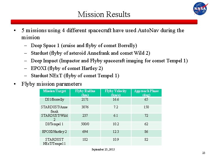
Mission Results • 5 missions using 4 different spacecraft have used Auto. Nav during the mission – – – Deep Space 1 (cruise and flyby of comet Borrelly) Stardust (flyby of asteroid Annefrank and comet Wild 2) Deep Impact (Impactor and Flyby spacecraft imaging for comet Tempel 1) EPOXI (flyby of comet Hartley 2) Stardust NEx. T (flyby of comet Tempel 1) • Flyby mission parameters Mission/Target DS 1/Borrelly Flyby Radius (km) 2171 Flyby Velocity (km/s) 16. 6 Approach Phase (deg) 65 3076 7. 2 150 STARDUST/Anne frank STARDUST/Wild 2 DI/Tempel 1 237 6. 1 72 500/0 10. 2 62 EPOXI/Hartley 2 694 12. 3 86 STARDUST NEx. T/Tempel 1 182 10. 9 82 September 23, 2015 23
Deep Space 1 • 1 st mission in NASA’s New Millennium Program – Goal was to test advanced technologies as part of a demonstration mission – DS 1 had 12 technologies, among which included: • Auto. Nav • Ion propulsion system • Miniature Integrated Camera and Spectrometer (MICAS) • Mission overview – Launch on October 1998 – Fly by asteroid Braille on July 1999 – Sole onboard star-tracker used to provide s/c attitude fails on August 1999. Results in long period where spacecraft in safe-mode while mission was redesigned to use MICAS camera as substitute star tracker. Long hibernation period results in dropping planned comet Wilson-Harrington flyby – Flyby of comet Borrelly on September 2001 September 23, 2015 24
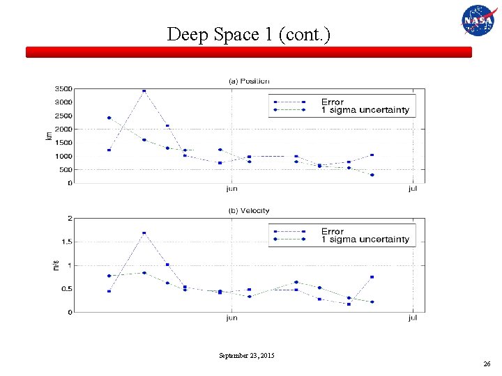
Deep Space 1 (cont. ) • Original plan was to have Auto. Nav control interplanetary cruise and asteroid/comet flybys • Initial results from camera images, however, showed several unforeseen issues with MICAS – Images heavily corrupted by stray light – Sensitivity of camera not as good as expected – Camera distortions unusual and difficult to model • Much of Auto. Nav software had to be reprogrammed to accommodate camera issues and so validation of cruise results delayed until June 1999, 8 months after launch and only 2 months before Braille encounter • Results in late June and early July indicated that orbit estimates as good as can be expected, but not as good as pre-flight analysis predicted, due to lingering camera performance issues • Maneuver planning and execution occurred as planned, – OD had to be “seeded” from the ground in certain cases due to degraded perfomance September 23, 2015 25
Deep Space 1 (cont. ) September 23, 2015 26
Deep Space 1 (cont. ) • Encounter with Braille failed due to cosmic ray spoofing of Auto. Nav – Resulted in redesign of system with more robust error rejection • Following Braille encounter, Auto. Nav in control of cruise navigation until August star tracker failure. Since Auto. Nav required attitude information from star tracker, had to fly remainder of cruise using ground-based navigation • Borrelly encounter on September 23, 2001 – Lessons from Braille encounter applied, and new software uploaded by June 2001 – Flyby tracking initiated 32 minutes prior to closest approach – Auto. Nav performed successfully, tracking Borrelly until E- 2. 5 min, when slew rate exceeded spacecraft capability – Nucleus captured in 46 out of 52 image shuttered, resulting in best image at 46 m resolution on surface September 23, 2015 27
Stardust • 4 th mission of NASA’s low cost, PI led Discovery Program • Primary goal of mission was to fly through coma of comet Wild 2 and return samples to Earth. Second goal was to capture high resolution images of comet nucleus during flyby • Launch on February 1999 • Opportunistic flyby of asteroid Annefrank on November 2002 – Provided engineering test case of spacecraft operations at flyby, including test of Auto. Nav • Wild 2 flyby on January 2004 • Sample returned successfully to Earth in January 2006 • Cruise, comet approach, and Earth return all done using standard groundbased radiometric and optical navigation techniques September 23, 2015 28
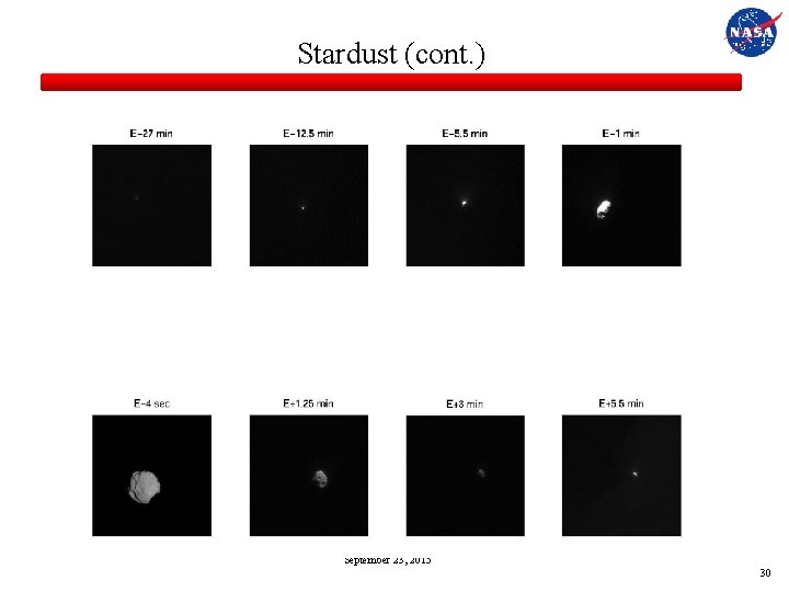
Stardust (cont. ) • Annefrank – High phase (150 deg) approach phase resulted in no ground-updates to target relative position at initiation of Auto. Nav – Auto. Nav started at E-20 min and tracked asteroid through encounter – Successful test increased confidence for Wild 2 encounter • Wild 2 encounter – Auto. Nav initialized at E-30 min with ground-based target-relative information accurate to 5 km crosstrack, 2000 km (or, equivalently, 50 seconds) in downtrack direction – Data accumulated for 20 min, 1 st OD update at E-10 min. – Auto. Nav initiated roll at E-4 min to align camera boresight rotation plane with flyby plane – End result successfully centered comet for approach, flyby, and departure September 23, 2015 29
Stardust (cont. ) September 23, 2015 30
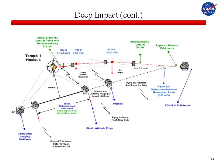
Deep Impact • DI was the eight mission in NASA’s Discovery Program • Goal of mission was to impact the comet Tempel 1 with one spacecraft while imaging the impact event with another • Flyby/Impactor combo launched on January 12, 2005 • Cruise for 6 months – Cruise and approach to comet performed using standard ground-based radiometric an optical navigation techniques • Impactor released from Flyby spacecraft at E-1 day. Flyby performs burn to slow down so that the impact can be observed prior to passing through closest approach • Modified DS 1 version of Auto. Nav used on both Impactor and Flyby – Impactor needed maneuver implementation to autonomous guide itself to impact site – Flyby version kept identical to Impactor version to minimize and simplify testing September 23, 2015 31
Deep Impact (cont. ) September 23, 2015 32
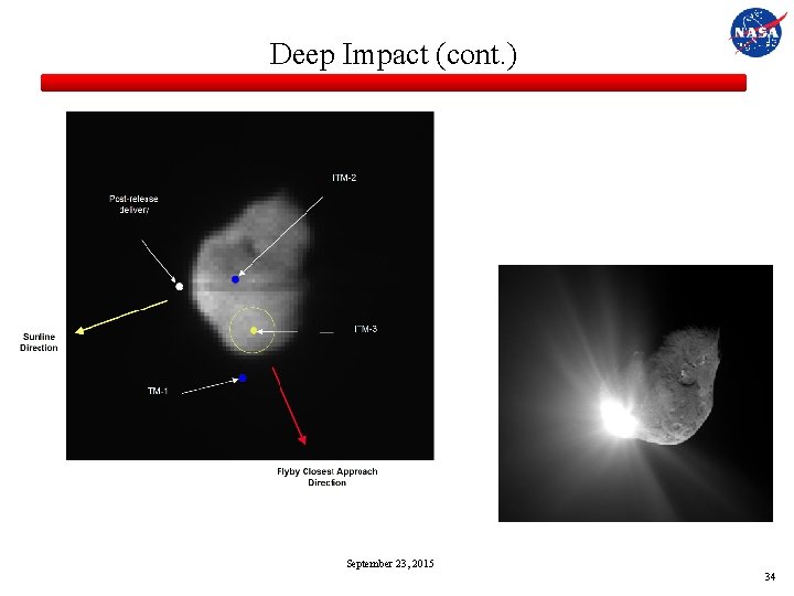
Deep Impact (cont. ) • Impactor Auto. Nav – – Initiated at E-2 hours with pre-release target-relative navigation knowledge Images taken at 15 sec intervals Data accumulated for 10 min, the 1 st OD update Maneuvers times pre-planned at E-90, 35, and 12. 5 min. Delta-V vector computed and implemented onboard – Image processing used “scene analysis” to direct spacecraft to impact site that was both lit, and biased towards the limb where the Flyby spacecraft made its overflight • Flyby Auto. Nav – Initiated at E-2 hours with post-release navigation knowledge – Used same image and OD cadence as Impactor, but no maneuvers performed – Used knowledge of expected impact time to update time of rapid image sequencing start to capture event September 23, 2015 33
Deep Impact (cont. ) September 23, 2015 34
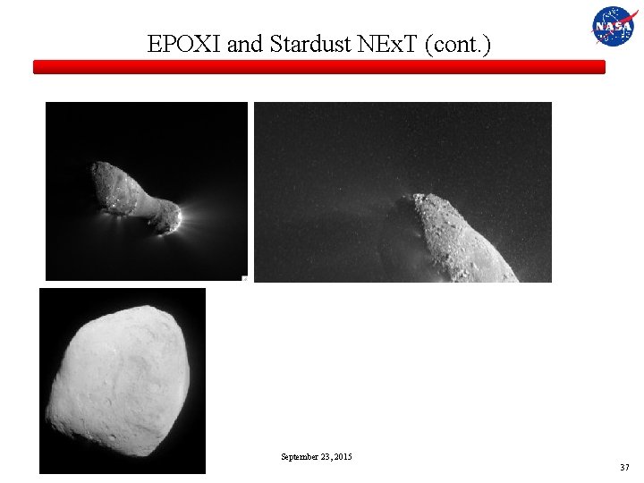
EPOXI and Stardust NEx. T • EPOXI was the follow-on mission for DI, selected as Discovery Mission of Opportunity in August 2007 – Healthy Flyby spacecraft following Tempel 1 encounter sent to encounter comet Hartley 2 – Following 3 year cruise with 4 Earth flybys, rendezvous with Hartley 2 occurred on November 4, 2010 – Goal was to image Hartley 2 using visible and IR detectors • Stardust NEx. T was the follow-on mission for Stardust, also selected as Discovery Mission of Opportunity in August 2007 – Stardust main spacecraft healthy after release of sample canister probe to Earth – Crater created by DI was not able to be imaged due to dust from the Impactor obscuring view, strong desire to see what crater was formed – Stardust sent to comet Tempel 1, marking 1 st time a comet was imaged from 2 different spacecraft at 2 different times – Goal was to image crater location, and any more of Tempel 1 that was feasible September 23, 2015 35
EPOXI and Stardust NEx. T (cont. ) • EPOXI Auto. Nav – DI software used unchanged. – Desire to image comet through approach, flyby, and departure resulted in some new twists due to interaction with attitude control system knowledge and errors (DI stopped imaging about 70 sec prior to closest approach) – Encounter imaging was successful, but leftover data from DI resulted in unforeseen offpoint at closest approach • Resulted in discovery of large particles being ejected from nucleus • Stardust NEx. T Auto. Nav – Stardust software used unchanged – Desire for high resolution images resulted in decision to flyby at altitude that was limit of spacecraft’s capability to track – Auto. Nav successfully tracked, although closest image slightly clipped September 23, 2015 36
EPOXI and Stardust NEx. T (cont. ) September 23, 2015 37
Potential Future Uses of Auto. Nav • Asteroid deflection – terminal guidance for high speed impact already demonstrated. Enhancements would allow for greater variability in approach velocity and target sizes • Gravity tractoring – maintaining hover location using low-thrust to pull asteroid using s/c gravity • Small body/Lunar pinpoint landing – numerical simulations indicate Auto. Nav capable of delivering lander to less than 3 m accuracies for small bodies and 20 m for the moon • Aerobraking – maintain safe aerobraking corridor at Mars • Outer plane satellite tour – rapid turnaround navigation could take advantage of delta-v and mission time savings in complex dynamical environment • Cube. Sat, Nano. Sats, etc. – multiple, small s/c exploration of solar system would severely tax DSN assets. Some type of Auto. Nav required to reduce navigation tracking time September 23, 2015 38
Investments in Technology Needed for Future Auto. Nav • Gimbal mounted cameras – Would reduce need to slew entire s/c to image objects. Allows for separation of s/c attitude maintenance and need for pointing • Miniaturization of camera systems – Smaller cameras for lower mass, needed for notional Cube. Sats or other small s/c. – Small aperture limitation for getting enough signal-to-noise for proper image processing • Enhanced image processing techniques – Would reduce/eliminate false detections and centroiding errors • Potential addition of other data types – Lidar, radar altimetry – One-way radiometric from the Earth or space assets – Two-way radiometric from the Earth or space assets September 23, 2015 39
Investments in Technology Needed for Future Auto. Nav • “Auto. Nav in a box” would: – Provide single piece of hardware that combines narrow-angle camera for navigation with wide-angle camera and IMUs for attitude control, and processor for Auto. Nav computations – Provide GPS-like functionality for most deep space applications (cruise, approach, orbit and landing) • Combination of Auto. Nav with AI enabled spacecraft would enable more autonomous spacecraft that can make decisions on its own September 23, 2015 40
References • • Bhaskaran, S. , et al, “Orbit Determination Performance Evaluation of the Deep Space 1 Autonomous Navigation System”, AAS 98 -193, AAS/AIAA Spaceflight Mechanics Meeting, Monterey, CA, February 1998. Bhaskaran. S. , et al, “Small Body Landings Using Autonomous Onboard Optical Navigation”, Journal of the Astronautical Sciences, Vol. 58, No. 3, 2012. Gaskell, R. H. , et al, “Characterizing and navigating small bodies with imaging data, ” AIAA Meteoritics and Planetary Science, Vol. 43, 2008, pp. 1049 -1061. Kubitschek, D. G. , et al, “Deep Impact Autonomous Navigation: The Trials of Targeting the Unknown”, AAS 06 -081, AAS Guidance and Control Conference, Breckenridge, CO, February 2006. Owen, W. M. , “Methods of Optical Navigation, ” AIAA/AAS Spaceflight Mechanics Conference, AAS 11 -215, New Orleans, LA, February 2011. Riedel, J. E. , et al, “Configuring the Deep Impact Auto. Nav System for Lunar, Comet and Mars Landing, AIAA 2008 -6940, AIAA/AAS Astrodynamics Specialist Conference, Honolulu, Hawaii, August 2008. Tapley, B. D. , Schutz, B. E. , Born, G. H. , Statistical Orbit Determination, Elsevier Academic Press, San Diego, CA, 2004. September 23, 2015 41
NESC Academy Webcast Questions? Upcoming GNC Webcast: Autonomous Spacecraft Navigation Using Above-the-Constellation GPS Signals Luke Winternitz Wednesday, December 9 th, 2015 2 PM Eastern
- Slides: 42