Nerf Football Launcher By Cory King 42415 Muthar

Nerf Football Launcher By: Cory King 4/24/15 Muthar Al-Ubaidi, Ph. D.

PROBLEM DEFINITION AND RESEARCH • Problem Definition • Background • Research: Technology and Existing Products • Customer Needs • Product Objective

Problem Definition & Background • Parents with injuries or handicaps often find it difficult to throw a football with their children. • It would be beneficial to these people to have a machine that can throw a football for them (there are no such products available in today’s market). • This would allow a person to spend quality time with their children while also getting their children active. Currently the only similar products available are made for high school and professional athletes. • Alternatively, this machine would allow peewee football teams to practice catches with consistent passes.

Existing Products The JUGS Football Machine™ Very powerful, $2, 500 USD. The Snap Attack football machine, Safety guards, finicky operation, $3, 999 USD.

Existing Products The Heater Sports CR 99 Ball Pitching Machine Low power, spin, $150 USD The Louisville Slugger Instructor UPM 30 Pitching Machine. Low power, uses arm, can not be modified to use a feeder, $130 USD.

Customer Needs Parents who would like to use this product were interviewed to determine customer needs: • Needs to be low cost • Needs to have safety features • Must be able to be operated by one person • Must not rock or tip (dangerous) • Must be easy to move (either light weight or on wheels) • Launch should be adjustable for different distances

Product Objectives • Customer features were determined based on customer needs and product research.

Product Objectives
")
Engineering Characteristics The product objectives were used to develop a Quality Function Deployment (QFD) chart which gives a visual representation of the weighted importance of each feature. Engineering Characteristics Quantitative Measures Relative Importance Speed of motor Angle of launching wheels RPM Degrees 5% 5% Height of body off of ground Feet 5% Operation switches Yes/No 10% Warning labels Safety guards Costs less than $200 Yes/No 5% 15% 20% Set-up time Weight Stability of tripod <5 minutes <35 lbs. ≥ 24” base 5% 15%

DESIGN ANALYSIS • • Design Alternatives Design Selection Solid Model Component & Material Selection

Design Alternatives • Concept 1 • This design consists of two wheels; one rotating CW and one rotating CCW. One wheel would be tilted at an angle to create spin on the ball. This concept uses a single motor with a belt and pulley drive. The pros of this design are its simplicity and low cost to manufacture. The cons of this design are that there already patents for similar designs and working around those would be difficult.

Design Alternatives • Concept 2 • This design concept uses three linear belts driven by multiple motors. All belts make equal contact with the ball. The pro of this design is that the ball has a consistent and straight path. The cons are that there is no spin on the ball and the path of travel cannot be adjusted.

Design Alternatives • Concept 3 • This design concept uses two advancing belts and one lateral belt below the ball plane. This gives the ball forward motion while also putting spin on it. The belts will be driven by two motors. The pros of this design are that the ball is thrown with a spiral and in a consistent path. The cons are that this design is more complicated to manufacture and that it has more pinch points.

Design Selection • Weighted Rating Method • A value was assigned to each concept design based on how it satisfied a given feature. (5 point scale) • The highest weighted total was then selected to become the design.
 Design Two Roller Wheels Three Roller")
Design Selection Weighted Rating Method (5 Point Scale) Design Two Roller Wheels Three Roller Belts Two Advancing Belts, One Lateral Belt 0. 15 3 3 3 0. 10 4 0 3 0. 05 3 3 3 0. 10 2 3 4 0. 10 4 4 4 Durability 0. 15 2 3 4 Price 0. 15 4 3 3 Safety 0. 10 2 3 4 0. 10 4 4 4 1 3. 10 2. 90 3. 55 Characteristics Evaluated Launch Speed Weight Adjustable Angle of Launch Ease of Cleaning Stability Speed Variability Consistency of Launch Weighted Total

3 D Model Assembly

Inside View

Overall Dimensions

Isometric Drawing
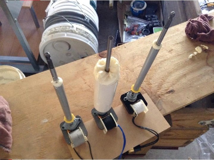
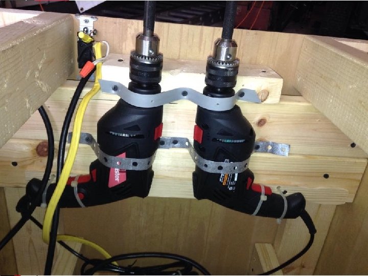

Component & Material Selection Drive Motors • Requirements of the drive motors: – – 120 VAC ¼ in. shaft High RPM Low HP

Component & Material Selection Lateral Spin Motor • Requirements of the lateral spin motors: – 120 VAC – ¼ in. shaft – High RPM – Low HP – Does not need to be Very powerful, only Spins a foam ball (low Resistance)

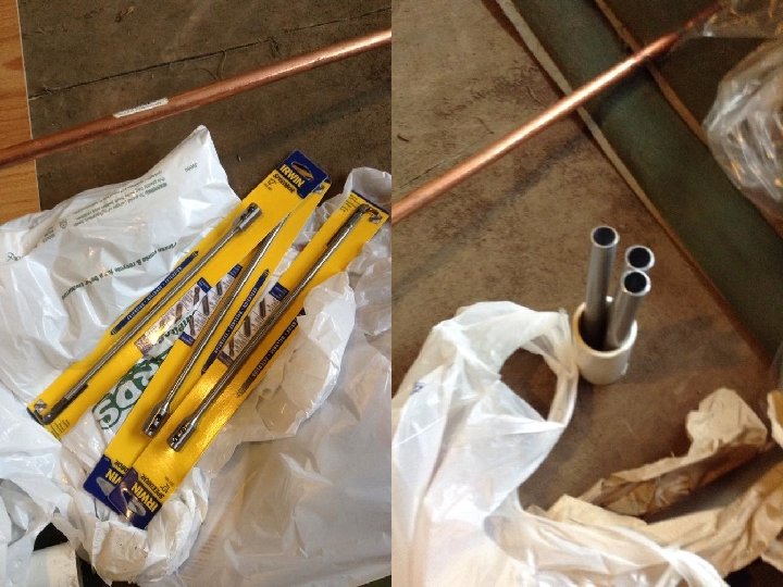
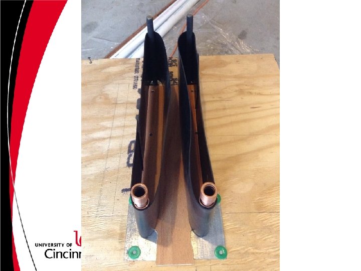
Component & Material Selection Belt Rollers • Requirements of the belt rollers: – Copper pipe will be used (low cost) – ½” inner, ¾” outter – Spins on ½” couplings – End caps to maintain belt alignment

Component & Material Selection Belting • Requirements of the belting: – Minimum 2 ply (durability) – Rubber – At least 6 in. wide

Component & Material Selection Leveling Feet • Requirements of the leveling feet: – Swivel – Minimum 3 in. long (for angle of launch) – 1/4 -20 threads

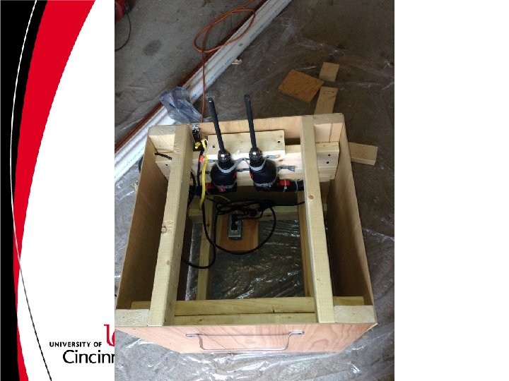
Material • • The enclosure will be made of clear Plexiglas The frame will be made of pine 2 X 4’s All mounting stretchers will be made of ¼ in. plywood Mounting brackets for the motors will be made of minimum 1/16 in. steel • Bracing for the motors will be made of thin sheet steel

Material • For the electrical connections 12 AWG. wire will be used. • All wiring will run to a single terminal strip with a single connection for a standard power cord. • Note: Standard rated components will be adequate.

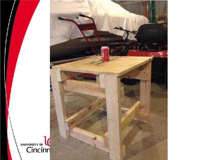
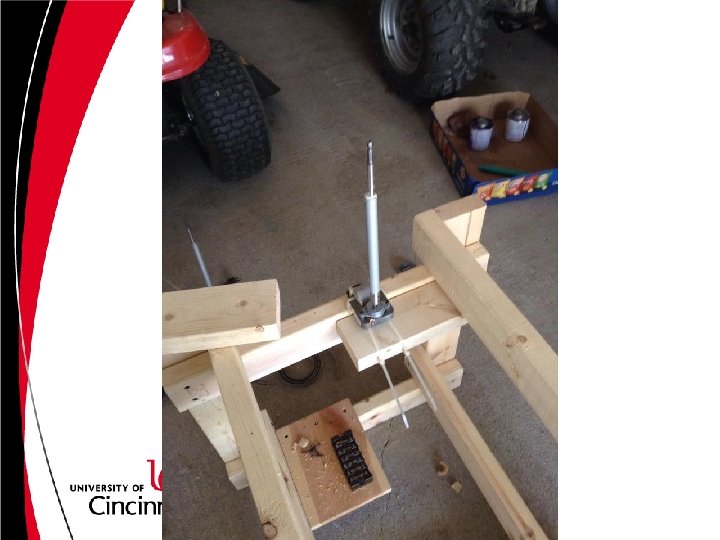
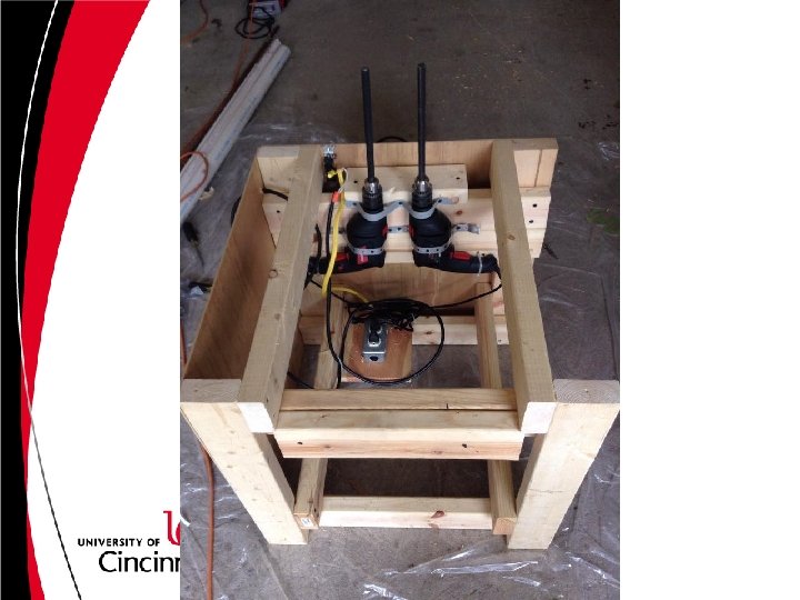
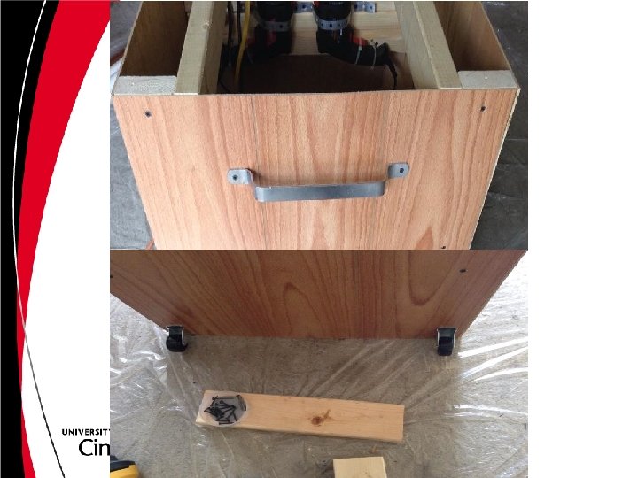
Planned Fabrication and Assembly • The bulk of assembly was done with hand tools and power tools. • A table saw was used for the Plexiglas • The stock motor shafts needed to be modified, a standard round stock fixture and horizontal band saw was used.

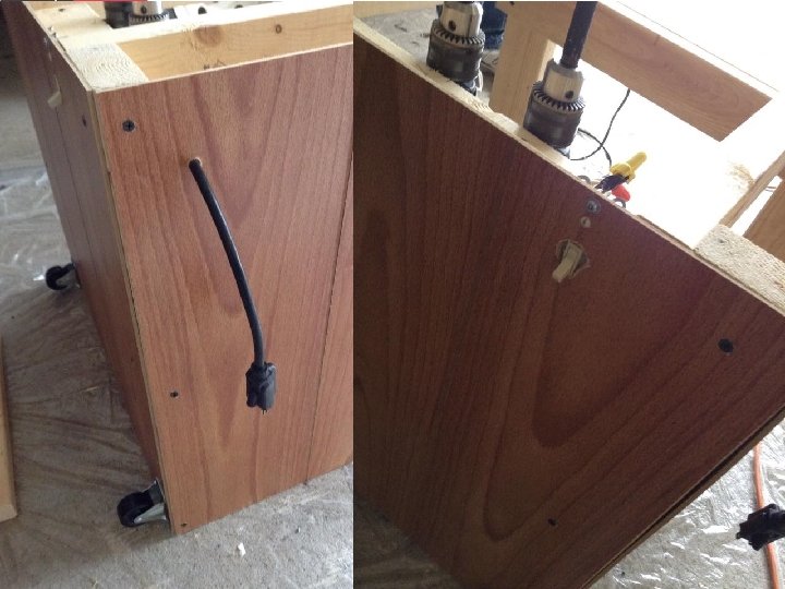
Planned Fabrication and Assembly • Standard fasteners will be used. • • • 1/4 -20 bolts Drywall screws Rubber glue for belts Silicone (RTV) will be used to seal all Plexiglas Note: Since Plexiglas was not used for the Expo, additional wood paneling was used.
 • Budget (Proposed vs. Actual)")
PROJECT MANAGEMENT • Schedule (Proposed vs. Actual) • Budget (Proposed vs. Actual)
")
Schedule Discussion (Proposed Vs. Actual)

Plan to Finsh • On February 4, 2015 a presentation was given to a panel of engineering professors. • Upon approval of the design (after incorporating suggested changes from the panel) parts and materials were purchased and construction began. (week of February 9) • Construction was completed by March 27 th. • Testing began the week of March 30 th. • Modifications were made. • Following this was the tech. expo and final presentation. • The report is being updated and will be completed by April 28 th. • The final report will be submitted online by May 1 st.

Bill of Materials
 • The Bill of Materials totals an estimated $371. 00. While")
Budget Discussion (Proposed/Actual) • The Bill of Materials totals an estimated $371. 00. While this is more than the original estimate, the design criteria and design type changed. This is still much cheaper than any similar product (by a factor of ten). • Adding up the multiple iterations of the project that were created the real total spent is nearly $900.

Questions?

Thank You Professor Muthar!
- Slides: 45