NEMA TS 2 Traffic Signal Cabinet Troubleshooting Course

NEMA TS 2 Traffic Signal Cabinet Troubleshooting

Course Outline Module 1: Introduction and Course Objectives Module 2: Module 3: Module 4: Module 5: History of NEMA Standard NEMA Cabinet Platforms NEMA TS 2 Standard – An Overview Definitions and Environmental Requirements (Sections 1 and 2) Module 6: Controller Units (Section 3) Module 7: Malfunction Management Unit (Section 4) Module 8: Terminals and Facilities (Section 5)

Course Outline Module 9: Module 10: Module 11: Module 12: Module 13: Module 14: Module 15: Auxiliary Devices (Section 6) Cabinets (Section 7) Bus Interface Unit (Section 8) Surge Protection Cabinet Troubleshooting Procedures Summary and Questions Hands-On

MODULE 1: INTRODUCTIONS AND COURSE OBJECTIVES

Course Learning Objectives § To develop an understanding of the NEMA TS 2 Standards § To develop an understanding of each of the components of a NEMA TS 2 Cabinet Assembly and their respective functionality § To be able to identify the platform of cabinet whether it be NEMA TS 1, NEMA TS 2 Type 1, or NEMA TS 2 Type 2 § To develop an understanding of the process of cabinet troubleshooting

MODULE 2: HISTORY OF NEMA STANDARD

Technology has come a long way!

1975 2009 NEMA Pre-Standards 1976 TS-1 1992 TS-2 Caltrans / NYDOT 1979 170 1985 179 1990 170 E 1995 2070 ATC 1999 - Developing Courtesy of Vanasse Hangen Brustlin, Inc. (VHB)

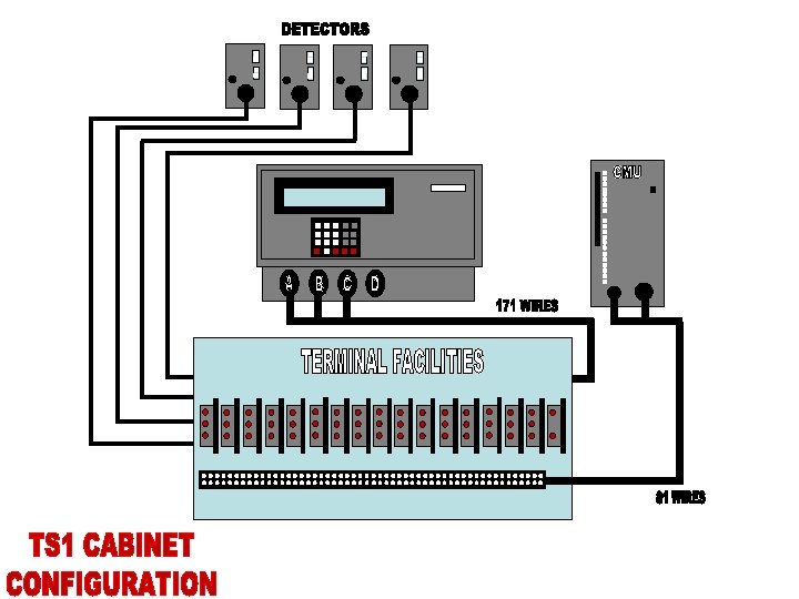
NEMA TS 1 Controller Platform § NEMA TS 1 Adopted in 1976 and reaffirmed in 1989 § Goal of the standard was to provide interchangeability among manufacturers § Functional standard § Included all equipment in the cabinet

NEMA TS-1 Controller Platform Disadvantages § Standard did not allow for expandability beyond the three connectors defined § MSD (fourth connector) is manufacturer specific and thus prevented interchangeability for enhanced controller functions such as coordination and preemption § Did not cover pretimed operation § Capabilities beyond traffic control not available § System communications not interchangeable

NEMA TS 1 Controller Platform Advantages § Defined effective basic actuated intersection control § Allowed for interchangeability among manufacturers for basic functions by defining the A, B, and C Connectors § By not specifying hardware, controller capabilities expanded with technology

NEMA TS-1 Controller Platform With Enhanced Features 12

NEMA TS-2 Controller Platform § Developed in 1992 and formally approved by NEMA to overcome the limitations of TS 1 § Standard defined two types of controllers • TS 2 Type 1 – utilizes high speed serial bus • TS 2 Type 2 – retains MS connectors allowing for downward compatibility § Included pretimed control operation and cabinet standards § NEMA TS -2 Reaffirmed in October, 1998 and again in May, 2003 to include NTCIP requirements

NEMA TS 2 Objectives § Define equipment requirements based on valid engineering concepts § Allow for Interchangeability without precluding downward compatibility of TS 1 equipment § Develop enhanced diagnostics § Minimize potential malfunctions § Provide for future expandability § Allow for enhanced user interface § Define advanced traffic signal operations such as coordination and preemption § Advanced cabinet monitoring and diagnostics

NEMA TS 2 Standard - Proposals 1. Standardize the present “D” connector 2. Free up seldom used pins on MSA, MSB, and MSC connectors and reassign them for enhanced functions 3. Proceed with an entirely new standard 4. Proceed with proposal 1 then move to proposal 3 for the long term solution

Results of the NEMA TS 2 Standard Development Process § Decision made to go with Proposal 3, provide for two types of cabinet platforms: • TS 2 Type 1 – utilizes high speed serial bus • TS 2 Type 2 – retains MS connectors allowing for downward compatibility § Let the end user decide on what platform best meets their short and long term requirements

MODULE 3: NEMA CABINET PLATFORMS

PA P 2 P 1 ENET P 3

Two Types of NEMA TS 2 Controllers § TS 2 Type 1 PA P 2 P 1 P 3 ENET § TS 2 Type 2 PA P 2 P 1 ENET • “Pure” TS 2 Controller • Small MS A connector for Power and Fault Monitor • Communication to cabinet devices via Port 1 SDLC bus P 3 • Downward compatible to TS 1 • MS A, B, and C connectors plus Port 1 SDLC for communication to MMU

PA P 2 P 1 ENET P 3

“Pure” TS 2 Type 1 Cabinet Configuration § Communication between cabinet equipment accomplished via Synchronous Data Link Control (SDLC) Bus eliminating MS A, B, and C connectors – “SDLC is highway for cabinet communications” § Communication to Terminal Facilities (TF) and Detector Rack via SDLC bus through Bus Interface Units (BIUs) § Malfunction Management Unit (MMU) communicates to controller through SDLC bus and retains discrete point-to-point wiring to TF § Eliminates most point-to-point wiring connections making for less points of failure

PA P 2 P 1 ENET P 3

TS 2 Type 2 Cabinet Configuration § Minimum requirement that the controller and MMU be connected via the Port 1 SDLC bus § Controller has both Port 1 connector to interface with SDLC bus and MS A, B, and C connectors to interface with TF § Type 2 allows for downward compatibility with TS-1 cabinets

Time for a Quiz!

NEMA TS 2 Cabinet Assemblies TS 2 Type 1 or TS 2 Type 2 ?

NEMA TS 2 Cabinet Assemblies TS 2 Type 1 or TS 2 Type 2 ?

NEMA TS 2 Cabinet Assemblies TS 2 Type 1 or TS 2 Type 2 ?

NEMA TS 2 Cabinet Assemblies TS 2 Type 1 or TS 2 Type 2 ?

MODULE 4: NEMA TS 2 STANDARD – AN OVERVIEW

Benefits of NEMA TS 2 Standard § Enhanced standardization § Enhanced safety & reduced liability § Upgrade path for expansion & innovation § Greater opportunity for multiple sourcing

NEMA TS 2 Standard Enhanced Standardization § TS 2 specifies controllers and cabinets more fully than TS 1 § Defines advanced functionality such as coordination, preemption, and time base control § Defines detector programming to allow for individual detector channels

NEMA TS 2 Standard Enhanced Standardization § Specifies all connections inside traffic cabinet § Eliminates manufacturer-specific “D” connector § Specifies cabinet dimensions § Type 2 allows for downward compatibility with TS 1 cabinets

§ § § § § NEMA TS 2 Standard Enhanced Safety and Reduced Liability Simplified cabinet wiring Redundant MMU functionality Program verification (Controller and MMU) Provision for output monitoring Clearance time monitoring AC power monitoring Detector status and failure monitoring Cabinet-level diagnostics Enhanced controller logging

NEMA TS 2 Standard Enhanced Safety and Reduced Liability v Simplified Cabinet Wiring v 15 wire SDLC bus replaces 171 wire A, B, and C cables v Redundant MMU Functionality v A TS 2 controller can put the intersection into flash if the MMU fails v Program Verification v Controller and MMU verify each others program every 100 msec

NEMA TS 2 Standard Enhanced Safety and Reduced Liability v Output v Monitoring The MMU can compare the load switch output to the controller output v Clearance v Time Monitoring The MMU times the interval between conflicting greens and yellow clearance time v AC v Power Monitoring The MMU monitors incoming power for low voltage and brownout conditions

NEMA TS 2 Standard Enhanced Safety and Reduced Liability v Enhanced v v v Controller Logging Detector Report Events Report MMU Report

Upgrade Path for Expansion and Innovation Open architecture at cabinet level § Made possible by SDLC bus § Interface to as yet unspecified cabinet devices Open architecture at system level § Made possible by standardized telemetry port and NTCIP Communications Protocol “Technology platform” for future ITS applications

NEMA TS 2 Standard - Overview § Section 1 – Definitions § Section 2 – Environmental Requirements § Section 3 - Controller Units § Section 4 - Malfunction Management Unit (MMU) § Section 5 - Terminals and Facilities § Section 6 - Auxiliary Devices § Section 7 - Cabinets § Section 8 - Bus Interface Unit (BIU)/Synchronous Data Link Cables (SDLC)

NEMA TS 2 Cabinet Assembly
")
MODULE 5: DEFINITIONS AND ENVIRONMENTAL REQUIREMENTS (SECTIONS 1 AND 2)

Section 1 - Definitions § Includes definition of new devices and functions defined by TS-2 • • • BIU – Bus Interface Unit CU – Controller Unit DR – Detector Rack MMU – Malfunction Management Unit TF – Terminals and Facilities AD-Auxiliary devices Coordination Preemption Time Base Control Detection

Section 2 – Environmental Requirements § Establishes limits for environmental and operating conditions in which a device will perform. § Defines a series of minimum test procedures to ensure device conformance to the standard. • Endurance tests • Shock tests • Electrical tests

Section 2 – Environmental Requirements § Environmental and Operating Standards • • Operating Voltage – 120 VAC Operating Frequency – 60 Hz +_ 3 Hz Temperature – -34 C (-30 F) to +74 C(+165 F) Humidity – 95 %
")
MODULE 6: CONTROLLER UNITS (SECTION 3)

Controller Units § Physical Standards § Interface Standards § Functionality § Modes § Unit Types § NTCIP

Controller Unit Physical Standards Configurations PA P 2 P 1 P 3 ENET PA P 2 P 1 ENET Source : NEMA TS 2 - 2003 Standards Publication Section 3. 2 P 3

Controller Unit Physical Standards Configurations § Maximum height = 12” § Maximum width = 19” (allowed for rack mounting) § Maximum depth = 14. 5” * * - This dimension includes connectors, harnesses and protrusions.
")
Controller Unit Interface Standards – Type A 1 and P 1 § Input/Output (I/O) for CU to MMU/DR/TF/AD is defined under section 3. 3. 1 § Section 3. 3. 1 defines the high speed, full duplex communications protocol which links all of the control cabinet assemblies devices.

Controller Unit Interface Standards – Type A 2 and P 2 § I/O for CU to MMU/DR is defined under section 3. 3. 1. § I/O for CU to TF/AD and any shelf mounted detectors is defined under section 3. 3. 5.

Controller Unit Interface Standards – Type 1

Section 3. 3. 1 - Port 1 Physical/Protocol § Port 1 connector is defined as a 15 pin, metal shell, D sub-miniature connector § Provides for in-cabinet data transfer § Communication protocol conforms to IBM document GA 27 -3093 -3 dated June 1986 for SDLC (Synchronous Data Link Control) data transfer PA P 2 § Bit rate of 153, 600 bps P 1 ENET P 3

Port 1 Pin Assignments Source : NEMA TS 2 - 2003 Standards Publication Section 3. 3. 1. 1
 is a")
How does SDLC communications work? § Synchronous High-level Data Link Control (SDLC) is a transmission protocol that structures information into well defined data “frames” that allow for a high speed exchange of data between devices. Based on an ISO standard developed by IBM in the 1970’s.

Port 1 – SDLC Frame Format § SDLC transmission Frame Format • • • Opening Flag – 0111 1110 (7 E hex) Address – 8 Bits Control – 8 Bits Information – Variable Length CRC – 16 Bits Closing Flag – 0111 1110
 – BIU Addresses Note: Address 255 – Date and Time Broadcast")
Port 1 (SDLC) – BIU Addresses Note: Address 255 – Date and Time Broadcast to all
 Frame Transfer § Primary Station")
Section 3. 3. 1. 4 - Port 1 (SDLC) Frame Transfer § Primary Station (Controller Unit) • § Command Frames (#0 -63 defined by NEMA TS 2) Secondary Station • Response Frames (#128 -191 defined by NEMA TS 2)
 Frame Transfer § See Table")
Section 3. 3. 1. 4 - Port 1 (SDLC) Frame Transfer § See Table 3 -1 for Command Frame Definitions • • § Command Frame Type 1 – MMU Inputs/Status Request (Address 16) Command Frame Type 9 – Date and Time Broadcast to all (Address 255) See Table 3 -2 for Response Frame Definitions • Command Frame Type 129 – MMU Inputs/Status (Type 1 ACK)
 Frame Timing § Transmission of")
Section 3. 3. 1. 5 - Port 1 (SDLC) Frame Timing § Transmission of Port 1 command frames is determined by Controller Unit § Primary Station transmits all command frames within a one second window § See Table 3 -3 “Command Frames and Frequency of Transmission • Most transmission requests are made 10 times per second (every 100 milliseconds, ex. Command Frame # 10 - TF BIU # 1 Output/Inputs requests)

Section 3. 3. 2 - Port 2 Physical/Protocol § Port 2 connector is defined as a 25 pin, metal shell, D sub-miniature connector § Provides for communications to a laptop computer or printer § Uses industry standard interface protocols PA P 2 P 1 ENET P 3

Port 2 Pin Assignments Source : NEMA TS 2 - 2003 Standards Publication Section 3. 3. 2

Section 3. 3. 3 - Port 3 Physical/Protocol § Port 3 connector is defined as a 9 pin, metal shell, D sub-miniature connector § Provides for system communications § Currently used for manufacturer specific communications protocol. Future support for NTCIP. PA P 2 P 1 ENET P 3

Port 3 Pin Assignments Source : NEMA TS 2 - 2003 Standards Publication Section 3. 3. 3. 1

Section 3. 3. 4 – Type 1 Controller Unit Input/Output Interface § The input/output connector is defined as a 10 pin, metal shell, MS connector § Often referred to as “small” MS “A” connector § Provides for power to the controller § Also provides for fault monitoring and logic ground outputs PA P 2 P 1 ENET P 3

Type 1 Controller Unit - MS “A” Connector Pin Assignments Source : NEMA TS 2 - 2003 Standards Publication Section 3. 3. 4

Controller Unit Interface Standards – Type 2

Section 3. 3. 5 Type 2 Interface Standards § Uses three MS connectors similar to NEMA TS-1 standards. § Expanded input and output functions through the reassignment of 24 I/O connections previously defined by NEMA TS-1. PA P 2 P 1 ENET P 3

Section 3. 3. 5 Type 2 Interface Standards § Input/Output Logic Levels • Low State – True (nominal 0 volts) = ON • High State – False (+24 v DC) = OFF § Electrical Limits of Inputs/Outputs • • Inputs – 0 -8 v. DC shall be considered Low (ON) Inputs – >16 v. DC shall be considered High (OFF) Inputs – 8 -16 v. DC shall be considered transition Outputs – 0 -4 v. DC shall be considered Low (ON)

Type 2 Input/Output Mode Bits § There are three pins on the MS A connector which represent Status Bits (A, B, and C) § Depending on the state (ON/OFF) of these pins, 24 inputs/outputs on the MS A, B, C connectors (171 wires) will be redefined

Type 2 Input/Output Mode Bits Source : NEMA TS 2 - 2003 Standards Publication Table 3 -13

NTCIP Requirements

What is NTCIP? § NTCIP stands for the National Transportation for Communications for ITS Protocol § NTCIP is a communications protocol standard § NTCIP is not a software standard for central or field control equipment!

History of NTCIP § NTCIP started by NEMA in 1992 § NTCIP concept endorsed by FHWA in 1993 § NTCIP Joint Committee formed in 1996 • Endorsed & Funded by FHWA • ITE Members • AASHTO Members • NEMA Members

What are the objectives of NTCIP? § Development of a set of communication standards that is intended to provide for the Interchangeability and Interoperability of electronic traffic control devices.

Interoperability § Different types of devices, supplied by separate vendors, all communicating over the same channel

Interoperability TS WS CCTV CMS RM HAR Vendor MIBs Source : Vanasse Hangen Brustlin, Inc. (VHB)

Interchangeability § The ability to interchange different brand of the same device on the same communication channel

Interchangeability A B Vendor A C Vendor MIBs Vendor C Source : Vanasse Hangen Brustlin, Inc. (VHB) Vendor B

NTCIP Requirements § NTCIP Objects • Mandatory • Optional • Vendor Specific

Section 3. 5 Actuated Control § Defines the functional capabilities of both the type 1 and type 2 controller unit § Includes all of the controller functionality defined by TS 1 plus enhanced operations

Standards on Features not included in TS 1 § Coordination § Preemption § Time Based Coordination § Conditional Service § Dual Entry § Simultaneous Gap Out - Inhibit § Lead/Lag & Alternative Sequencing

Standards on Features not included in TS 1 § Exclusive Pedestrian Operations § Manual Control Enable § Protected Pedestrian Clearance § Detector Extend, Delay, Switch § Dimming by Phase or Color § Internal Diagnostics § Uniform Code Flash (UCF)

Diagnostics § Memory § Processor Monitor § Detector Diagnostics • No Activity • Max Presence • Erratic Activity § Event Reports § Operator Initiated Diagnostics

User Interface § Entry • Keypad • Port 2 interface to laptop § Display • Minimum 2 lines @ 16 characters/line • Port 2 interface to laptop
")
MODULE 7: MALFUNCTION MANAGEMENT UNIT (SECTION 4)
 § Configuration Options")
Malfunction Management Unit § Purpose of a Malfunction Management Unit (MMU) § Configuration Options § Physical/Interface Standards § Functionality/Operation

Purpose of a Malfunction Management Unit § Detect and Respond to improper and potentially dangerous field operating conditions resulting from malfunction of the cabinet equipment, field wiring, or signal heads.

Purpose of a Malfunction Management Unit § Display the cabinet status and monitor fault status § Diagnose the cause of the malfunction with accurate information § Reduce liability by acting as a first defense for malfunctions

Malfunction Management Unit § The MMU detects the following faults: • Voltage on conflicting field terminals • Absence of proper voltages on all field terminals of a channel • Presence of satisfactory operating voltages within the CU and the MMU itself

STOP – OBSERVE – DOCUMENT – THINK – TAKE ACTION § Don’t be quick to push the reset button!!! § Before you reset the monitor, record the information displayed § Take the appropriate time to identify the problem and take corrective action § Don’t Panic!!!

MALFUNCTION MANGEMENT UNIT Two Modes of Operation § Type 12 mode monitors four 120 Volt AC input circuits for up to 12 load switch “Channels”. • • § Green Yellow Red Walk Type 16 mode monitors three 120 Volt AC input circuits for up to 16 load switch “Channels”. • • • Green/Walk Yellow Red/Don’t Walk

MALFUNCTION MANGEMENT UNIT Two Modes of Operation § Type 12 • “Out of Box” configuration • Downward compatible to TS 1 (12 channel CMU) § Type 16 • Utilizes separate channels for full pedestrian monitoring

MALFUNCTION MANGEMENT UNIT Two Modes of Operation

How do you switch between a Type 12 and a Type 16 MMU operation? In a TS 2 Cabinet Assembly, there is an input on the back panel called “Type Select”. By grounding this input, the MMU operates as a 16 channel device. By not grounding the “Type Select” input, the MMU defaults to a 12 channel mode. • • Logic True (> 16 VDC) = Type 16 Mode Logic False (< 8 VDC) = Type 12 Mode

Section 4. 3. 1 MMU Port 1 Physical/Protocol § The Port 1 connector is defined as a 15 pin, metal shell, D sub-miniature connector § Provides for in-cabinet data transfer § Port 1 is disabled when used as Type 12 monitor unit

MMU Port 1 Pin Assignments Source : NEMA TS 2 - 2003 Standards Publication Section 4. 3. 1

Section 4. 3. 2. 1 MMU Connectors Physical § Connector A – 55 Pin MS style • Note: Pin HH (Input) – Type § Connector B – 26 Pin MS style B A

MALFUNCTION MANAGEMENT UNIT Control Inputs § The following inputs are constantly monitored: • • • Reset Controller Voltage Monitor (CVM) +24 Volt Monitor Inhibit Type Select Local Flash Port 1 Disable

MALFUNCTION MANAGEMENT UNIT Field Signal / Channel Inputs § A channel is considered active if a Green, Yellow, or Walk input circuit is greater than 25 VAC § The channel is inactive if less than 15 VAC • > 25 VAC = ON (Active) • < 15 VAC = OFF (Inactive) § The channel Red input is ON when the measured voltage is greater than 70 VAC § The Red input is considered OFF when the measured voltage is less than 50 VAC • > 70 Volts AC = ON (Active) • < 50 Volts AC = OFF (Inactive)

MALFUNCTION MANAGEMENT UNIT § There are two relays: Outputs • Output Relay (MS A Connector) DPDT 3 A @ 135 VAC • Start Delay Relay (MS B Connector) SPDT 3 A @ 135 VAC § When the MMU detects a fault condition, the Output Relay is placed in the "fault" state placing the cabinet in flash.

MALFUNCTION MANAGEMENT UNIT Outputs § The Output Relay is also held in the "fault" state during the Minimum Flash Time after AC power is applied to the MMU. § The Minimum Flash Time is programmed using soldered wire jumpers on the Programming Card.

MALFUNCTION MANAGEMENT UNIT Outputs § The Start Delay Relay controls the AC power to the controller unit. • Transfers power to the controller unit for normal operation two (2) seconds after the MMU powers up. • Moves to the power-down state if an AC brownout occurs.

Section 4. 3. 5 MMU Display § The following is a listing of minimum displays for an MMU: • Conflict Monitoring • Voltage Monitoring • Red Monitoring • Minimum Yellow/Red Clear Monitoring • Time Out Failure on Port 1 • Microprocessor/Memory Monitoring • Local Flash Status • Status/Channel for an active G - Y - W

Section 4. 3. 6 MMU Programming Card § The MMU contains a programming card similar to the card defined by TS 1 § The card is not interchangeable with the TS 1 programming card

Section 4. 3. 6 MMU Programming Card § MMU functionality is programmed by soldering wire jumpers into the pair of holes associated with each function on the Programming Card. § This allows the user to define the permissive channel indications and customize the following functions: • 120 Permissive Channel jumper locations • 16 Minimum Yellow Change Channel Disable jumper locations • 4 Minimum Flash Time jumper locations • 24 Volt Latch Enable jumper • Controller Voltage Monitor Latch Enable jumper

MMU Programming Card – Permissive Channel Jumpers § The absence of a soldered wire jumper in a Permissive Channel Pair location implies that any combination of signal indications of that channel pair is incompatible and non-permissive. (i. e. Jumper must be present for compatible channels) § Any two active channels not programmed as permissive result in the Conflict Fault § Simultaneous indications of Green + Green, Green + Yellow, or Yellow + Yellow on two non-permissive (or conflicting) channel pairs will fault the MMU after 350 milliseconds

MMU Programming Card – Minimum Flash Time Jumpers § The Minimum Flash Time controls the duration of “cabinet flash” when power is restored to the terminal facility. § The Programming Card provides four jumper hole pairs (labeled 8, 4, 2, and 1) § Program the Minimum Flash Time as the summation of the values associated with each jumper (8, 4, 2, and 1 second). § One additional second is added to this total to arrive at the Minimum Flash Time. § In addition, the Minimum Flash Time cannot be less than 6 seconds.

MMU Programming Card – Minimum Yellow Change Disable Jumpers § A Minimum Yellow Change fault occurs when the channel indications move directly from Green to Red (skipped Yellow), or the duration of the Yellow indication is less than 2. 7 seconds. § The Programming Card provides sixteen jumper hole pairs for disabling the Minimum Yellow Change monitoring for each channel. § Minimum Yellow Change monitoring is disabled when a jumper is soldered in that hole pair associated with a channel. § Note: Disable for pedestrian movements. • For example, to allow for a Phase 9 Pedestrian on channel 9, solder a jumper in the jumper position labeled 9 in the MYCD area.

MMU Programming Card – Latch Enable +24 V and CVM Jumpers § By default, these jumpers are normally not used, as it is not common practice to latch +24 V or CVM

MMU Faults AC Line Power Failure § The AC line voltage is continuously monitored to insure that the supply voltages are adequate § AC Line input considered ON if voltage >98 VAC § AC Line input considered OFF if voltage <89 VAC § MMU shall respond by transferring to fault condition if AC Line is OFF for 500 ms or more § A minimum of 3 VAC hysteresis is used to prevent the MMU from cycling in and out of a “brownout” condition when the line voltage hovers near 89 VAC. § This is not a latching fault

MMU Faults Conflict § MMU detects two or more normally incompatible channels to be active (25 VAC) together for more than 450 ms § This is a latching fault condition § Causes: v Burned out bulbs/LEDs v Shorted field wires v Programming Card not programmed properly v Faulty Load Switch v Controller ring sequence v Faulty MMU or BIU v?

MMU Faults Red Fail § MMU monitors for the absence of voltage on all inputs of a channel § Red Fail fault occurs if there is an absence of voltage on all inputs of a channel for more than 1000 ms § Red Fail monitoring shall be enabled when the Red Enable input is active (>89 VAC) § Red Fail monitoring shall be disabled when the Red Enable input is not active (<70 VAC) § This is a latching fault condition

MMU Faults Red Fail § A loss of load will NOT cause a Red Fail. A loss of load typically results in a Conflict or Dual Indication fault. § Causes: v. Bad flash transfer relay v. No jumper in unused load switch slot v. Bad load switch v. Improper flash wiring v. Faulty MMU v?

MMU Faults Minimum Yellow Clearance Fail § MMU verifies that the Yellow change interval on a channel is at least 2. 7 +/-. 1 seconds § The Minimum Yellow Clearance is enabled when the Red Enable input is active § This is a latching fault condition § Causes: v. Pedestrian Movements v. Short yellows (< 3 second) programmed in controller v. Faulty Controller, MMU or BIU v. SDLC error

MMU Faults Minimum Yellow + Red Clearance Fail § MMU verifies that the Yellow + Red change interval from a terminating Green to the start of a conflicting Green is at least 2. 7 +/-. 1 seconds § Provides clearance protection for pedestrian channels or channels with no yellow clearance § This is a latching fault condition § Causes: v. Pedestrian Movements v. Short yellows (< 3 second) programmed in controller v. Faulty Controller, MMU or BIU v. SDLC error

MMU Faults Port 1 Fail § When a type 0 frame has not been received by the MMU from the controller for 300 milliseconds § This function is disabled when Port 1 is disabled (Type 12 operation) § This is a latching fault after the 3 rd occurrence within a 24 hour period § Causes: – Faulty Controller, MMU or BIUs – EMI / RFI / Grounding Issues – SDLC Cable or Termination Issues –?
 § MMU monitors two")
MMU Faults 24 Volt Monitor (+24 V-1 and +24 V-2) § MMU monitors two +24 VDC inputs § Properation is greater than +22 VDC § Less than +18 VDC for more than 175 milliseconds is considered a fault condition § This is not a latching fault unless jumpers installed § Causes: – Bad cabinet power supply – Blown +24 VDC fuse in controller or cabinet power supply. – Faulty MMU
 § The controller will use this logic signal")
MMU Faults Controller Voltage Monitor (CVM) § The controller will use this logic signal to indicate a problem in the controller unit to force the MMU to the flash state § Normally True (Low) State, Floats False (High) when problem in controller causing MMU to flash state § This is not a latching fault unless jumpers installed § Causes: – – – Time-of-Day “Hard” Flash (CVM Flash) Faulty MMU or CVM output circuit Failing microprocessor or processor hiccup Critical SDLC Fault Common after power/surge events

MMU Faults Enhanced Monitoring § Dual Indication § Field Check § Programming Card Ajar
")
MODULE 8: TERMINALS AND FACILITIES (SECTION 5)

Terminals & Facilities § Panel Physical / Electrical Standards § Interface § Detector Rack Options § Cabinet Power Supply

Cabinet Facilities § Sets minimum requirements for component identification. This mandates that devices such as load switches, relays, flashers, circuit breakers, etc. be identified and permanently identified adjacent to the device.

Cabinet Facilities § Defines requirements for printed circuit boards § Wire Requirements • • Amperage Rating Type Splicing Cable Use

Cabinet Facilities § Cabinet Layout • Terminals for controller interface and load switches shall be located on the rear portion of the cabinet • Power distribution shall be located on the lower right side of the cabinet • Terminal facilities for loop and auxiliary interconnections shall be located on the left side wall

Cabinet Facilities § Cabinet Facilities • Load switch field terminals shall be located on the bottom half of the back or side of the cabinet. § Load switches and flashers shall be supported with at least 50% of the area under the device open to allow for a free flow of air.

Section 5. 3 Interface § This section defines configuration types including the quantities of : • • • Load Switches Flash Transfer Relay sockets Flasher sockets TF BIU’s Detector rack type configuration MMU type § This section also defines minimum terminals required for back panel

TS 2 Type 1 - Cabinet Configurations Configuration Type Load Switch Positions Flash Transfer Relays Flasher Sockets TF BIU’s Required Detector Rack Type MMU Type 1 4 2 1 16 2 8 4 1 16 3 12 6 1 2 2 16 4 16 6 1 2 2 16 Source : NEMA TS 2 - 2003 Standards Publication Table 3 -13

Section 5. 3. 1. 3 BIU Interface § This section defines the BIU rack requirements as well as defining the BIU input/output functions § BIU is an interchangeable device that supports data exchange for the terminal facilities and the detector rack

Section 5. 3. 1. 3 BIU Interface § Interfaces Detector Racks and Terminals and Facilities to SDLC bus § 15 -pin D connector on front panel to SDLC bus § 64 -pin DIN connector to back plane § I/O Configurations Include: • • • 15 Outputs 24 Inputs / Outputs 8 Inputs 4 Optically Isolated Inputs 4 address select inputs

Section 5. 3. 1. 3 BIU Interface § Operates on +24 VDC power § Input / Output Configurations § Configuration is determined by the application of the BIU § Addressing of the BIU is hardwired to the slot of the BIU being plugged into

What does a single BIU support? § Each Detector BIU can handle up to 16 channels of detection § Each TF BIU can handle 8 load switches
 = Supports Terminal Facility")
BIU Assignments § BIU 1 - 4 (Address 0 -3) = Supports Terminal Facility Functions such as load switch I/O, Preempt, Stop Time, Max 2, etc. § BIU 9 - 12 (Address 8 -11) = Detector Rack Function § BIU 5 - 6 & 13 - 14 = Reserved by NEMA § BIU 7 - 8 & 15 - 16 = Reserved for Manufacturers use

Section 5. 3. 4 - Detector Rack Configurations Source : NEMA TS 2 - 2003 Standards Publication Table 5 -9

Section 5. 3. 4 Detector Rack Type 2 Configuration 3 1 7 5 11 9 15 13 4 2 8 6 12 10 16 14 BIU Slot 1 Slot 2

Section 5. 3. 4 Detector Rack 2 Channel Detector Card 3 1 7 5 11 9 15 13 4 2 8 6 12 10 16 14 BIU Slot 1 Slot 2

BIU 9 Signal Assignments § Defines the Input / Output detector rack functions § One BIU supports up to 16 channels of detection § Maximum of 64 channels of detection with the use of 4 BIU’s

Section 5. 3. 5 Cabinet Power Supply § Cabinet power supply generates regulated DC power, unregulated AC power and a line frequency reference for the detector racks, BIU’s, load switches and other auxiliary cabinet devices § Shelf or rack mounted

Section 5. 3. 5 Cabinet Power Supply § Electrical Outputs: • +12 VDC @ 2. 0 amps • +24 VDC @ 2. 0 amps • 12 VAC @ 0. 250 amps § +12 VDC intended to power the detector cards only § +24 VDC intended to power the Load Switches and BIUs § 12 VAC intended for isolated inputs

Power Supply Pin Connections Source : NEMA TS 2 - 2003 Standards Publication Section 5. 3. 5. 4. 4

Section 5. 3. 6 Field Terminals § Standard nomenclature for terminal identification: • • Load switch 1 green = 1 G Detector Channel 1 Loop = L 1 A & L 1 B Pedestrian Detector = PC 1 Pedestrian Call Common = PC COMM Preempt 1 Detector = PE 1 Transmit 1 = TX 1 Receive 1 = RX 1
")
MODULE 9: AUXILIARY DEVICES (SECTION 6)

Auxiliary Devices § Load Switches § Flashers § Flash Transfer Relays § Inductive Loops

Load Switches, Flasher, and Flash Transfer Relays § Downward compatible with TS 1 § TS 2 load switch has peak leakage of 10 m. A, compared to 20 m. A for TS 1 § TS 2 flasher and flash transfer relay operate at 89 VAC, compared to 95 VAC for TS 1 § TS 2 specifies flash transfer relays both mechanically and electrically

Loop Detector Units § Rack mounted version only § Two and Four channel units § Each detector rack is interfaced to SDLC bus via a BIU § 16 detector channels per rack, BIU addressing for up to 4 racks § Can be powered by 10. 8 - 28. 8 VDC, compared to 24 + 2. 5 VDC for TS 1 § Powerful TS 2 diagnostic features § TS 2 makes provisions for 64 detectors, TS 1 only has 8

Loop Detector Units § Controls and Indicators • • Output Indicator Sensitivity Control Reset Mode Selector (Pulse / Presence) Crosstalk Control Delay/Extension Selection & Timing Control Enable/Disable

Loop Detector Units § Channel Status Reporting - requirements for channels status outputs: • • • Normal Operation Detector Unit Failure Open Loop Shorted Loop > 25% Inductance (L) Change § Connector Description • 44 Pin, double row, edge connector • Two and Four channels cards shall have all 44 input/output connector terminations (NEMA Table 6 -2)
")
MODULE 10: CABINETS (SECTION 7)

Control Cabinet § Physical Dimension § Definition of Types

Cabinets § This section defines cabinet requirements including but not limited to: • • Material Doors Door Stop Latching Locks Shelves Cooling Controls
 Width (inches) Height (inches) Depth (inches) 1")
Control Cabinet Dimensions NEMA Type/Size (FDOT Size) Width (inches) Height (inches) Depth (inches) 1 (2) 16 24 12 2 (3) 20 32 14 3 24 40 15 4 24 46 16 5 (4) 30 48 16 6 (5) 44 52 24 7 (6) 44 72 24 Source : NEMA TS 2 - 2003 Standards Publication Table 7 -1
")
MODULE 11: BUS INTERFACE UNITS (SECTION 8)

Bus Interface Unit § Functionality § Interface Requirements

Bus Interface Unit § BIUs perform the interface between Port 1 at the controller unit, terminal facilities, loop detector racks, and other devices § BIU functions include controlling load switch outputs, communicating with detector units, and the conversion of TF and DR inputs to the controller

Bus Interface Unit § 15 -pin D connector on front panel to SDLC bus § 64 -pin DIN connector to back plane § I/O Configurations Include: • • • 15 Outputs 24 Inputs / Outputs 8 Inputs 4 Optically Isolated Inputs 4 address select inputs

Bus Interface Unit § Operates on +24 VDC power § Input / Output Configurations § Configuration is determined by the application of the BIU § Addressing of the BIU is hardwired to the slot of the BIU being plugged into

BIU Connector Pin Assignments Source : NEMA TS 2 - 2003 Standards Publication Section 8. 8. 2. 1

MODULE 12: SURGE PROTECTION
: • • Grounding is used")
159 Grounding and Bonding (From IMSA Level III Field): • • Grounding is used to limit the voltage to ground potential during the normal operation of an electrical system to minimize excessive electrical energy due to lightning, line surges or unintentional circuit contact with higher voltage lines and to stabilize the voltage to ground during normal operations. (IAEI Soures Book on Grounding, 7 th Edition) Grounding of electrical equipment is not for the purpose of clearing ground faults. (Mike Holt’s NEC Series, Grounding and Bonding, Volume 2)
: • Bonding is the electrical")
160 Grounding and Bonding (From IMSA Level III Field): • Bonding is the electrical connection of conductive materials that may become energized under certain conditions to provide a low impedance path for clearing ground faults that would otherwise remain at an electrical potential above earth potential thus creating a shock hazard. (National Electric Code, 2008 Edition)
: • • “The grounding system")
161 Grounding and Bonding (From IMSA Level III Field): • • “The grounding system in the cabinet shall be divided into three separate and distinct circuits (AC neutral, Earth Ground, Logic Common), all of which shall be connected together at a single point. . . at the time of delivery” (NEMA TS 2 , Version 02. 06, Section 5. 4. 2. 1) “Field installation practices may require separating AC Neutral and Logic Common from Earth Ground within the cabinet. ” ( NEMA TS 2 Version 02. 06, Section 5. 4. 2. 1))

Types of Electrical Surges and Interference § Possible Causes • • Nearby Lightning Strikes Power Surge Events EMI (Electromagnetic Interference) RFI (Radio Frequency Interference)
 § Moderate or")
EMI / RFI Sources § Various Circuitry § CRT Monitors (Displays) § Moderate or High Powered Wireless Transmitters • • • Broadcast Station Radio Transmitters Television Transmitters Pager Transmitters (!) Airports § High Power Transmission Lines § High Current Circuits

EMI / RFI Protection § Good Electrical Grounding System! § Shielded Loop lead-in Cables • Properly terminated to Earth Ground on one end only • The opposite end should be left floating • Grounding both ends causes Ground Loops! § Line Filters § Braided Cables for RFI
 § Surge Protection Devices attempt to limit transient voltages from")
Surge Protection Device (SPD) § Surge Protection Devices attempt to limit transient voltages from exceeding the basic impulse level (BIL) of the electrical distribution, or the break over voltage of electronic equipment § Surge Protection Devices are only as good as the grounding system where they can dissipate the energy

Surge Protection Devices § Power Panel Protection • Line Filter/Surge Protection Device • Solid State Mercury Relay • RFI Braid § Back Panel Protection • MOVs (LS and Field Outputs) • MOVs (FTRs) § Cabinet Protection • RC (Snubber) Network – Fan/Thermostat • RC (Snubber) Network – Cabinet Lamp

Surge Protection Devices § Loop Interface Panel • Loop Surge Protection Devices § Pedestrian Push Buttons • Optical Isolation § Video Detection Surge Protection § Communication Cable / Telemetry Surge Protection

MODULE 13: CABINET TROUBLESHOOTING PROCEDURES

IMSA’s 7 Step Troubleshooting Process 1. Observe intersection operation 2. Identify the problem or problems 3. Determine the general areas the could create the observed symptoms 4. Make tests or take steps to isolate the actual area causing the problem 5. Make tests to determine the device that is causing the problem 6. Replace the defective device or otherwise correct the problem 7. After corrective measures are completed, thoroughly observe intersection operation to ensure that all problems have been corrected

“It’s in Flash!”. . . Now what? DON’T TOUCH ANYTHING!!!! § § § Observe the entire situation Accidents Weather conditions Construction Time of day / night Location: near schools, bad neighborhood, etc.
 § Don’t")
Don’t Panic!!! § Open the cabinet (If you have one to open) § Don’t touch—just look § Look, Listen and Smell • Are there any lights in the cabinet? • Do you hear relays chattering or wires arcing together? • Do you smell anything burning?

Look and Write it Down § § What does the Conflict Monitor Display? Read ALL the LED’s or LCD Display Channels 1 thru 16 Condition - Red Fail (bad load switch, controller output or BIU) - Conflict (Bulb burned out, shorted or open field wire, bad load switch) - 24 volts (where does 24 volts come from? ) - Watch Dog (microprocessor) - CVM or BND (line voltage to controller) - Port 1 Fail (check SDLC cables, bad - BIU or controller malfunction

Look and Write it Down § What does the controller display? § Read ALL of the display § Is the controller “stopped” at the point of trouble? § What phases are showing? § What intervals are showing? § Other status display—Max II, preemption, coordination, master controller or system

What Type of Problem? § Dark intersection § Flashing intersection § Cycling problem Begin to Divide and Conquer

Dark Intersection § Check the line voltage at the power termination point (AC to Neutral/AC to Ground/Neutral to Ground). § Is the main breaker tripped? § Are the door switches in the “on” position? § Do the load switches have power? § Are the Flash Transfer Relays in place? § Is the flasher operating as it should?

Flashing Intersection Something put the intersection into flash? § Begin to look for the reason why § Start with the MMU and controller § Check door and controller switches § Check the rest of the cabinet components (BIU’s and SDLC) § Is it a cabinet or field problem? Divide and conquer from the field terminals

Cycling Problem Not Cycling § Detection § Phase enabled § Proper timing in the controller (compare the controller settings with the timing sheet) § Preemption § Coordination § Stop time switch (controller or door)

MODULE 14: SUMMARY AND QUESTIONS
- Slides: 177