
NED heat transfer program at CEA Jaroslaw Polinski

- Slides: 41
NED heat transfer program at CEA Jaroslaw Polinski, Bertrand Baudouy CEA/DAPNIA/SACM J. Polinski, B. Baudouy -The NED heat transfer program at CEA Saclay, January 11 th 2008 1
Contest • Motivations of the program • Cryostat NED • Conventional insulation (Kapton) – Saclay sample • Ceramic (innovative) insulation – KEK sample • RAL conventional insulation – drum method • Technical solutions investigation • Conclusions J. Polinski, B. Baudouy -The NED heat transfer program at CEA Saclay, January 11 th 2008 2
Contest • Motivations of the program • Cryostat NED • Conventional insulation (Kapton) – Saclay sample • Ceramic (innovative) insulation – KEK sample • RAL conventional insulation – drum method • Technical solutions investigation • Conclusions J. Polinski, B. Baudouy -The NED heat transfer program at CEA Saclay, January 11 th 2008 3
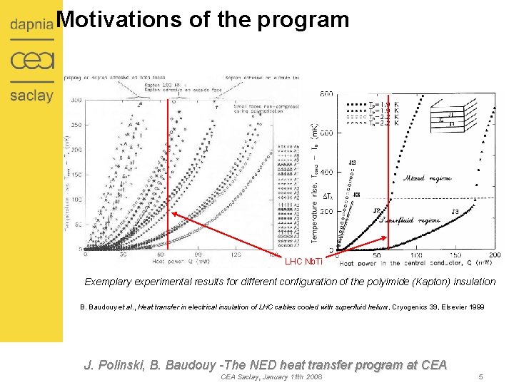
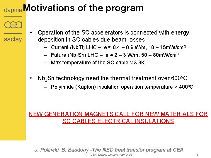
Motivations of the program • Operation of the SC accelerators is connected with energy deposition in SC cables due beam losses – Current (Nb. Ti) LHC – e ≈ 0. 4 – 0. 6 W/m, 10 – 15 m. W/cm 3 – Future (Nb 3 Sn) LHC – e ≈ 2 – 3 W/m, 50 – 80 m. W/cm 3 – Max temperature of the SC cable ≈ 3. 3 K J. Polinski, B. Baudouy -The NED heat transfer program at CEA Saclay, January 11 th 2008 4
Motivations of the program LHC Nb. Ti Exemplary experimental results for different configuration of the polyimide (Kapton) insulation B. Baudouy et al. , Heat transfer in electrical insulation of LHC cables cooled with superfluid helium, Cryogenics 39, Elsevier 1999 J. Polinski, B. Baudouy -The NED heat transfer program at CEA Saclay, January 11 th 2008 5
Motivations of the program • Operation of the SC accelerators is connected with energy deposition in SC cables due beam losses – Current (Nb. Ti) LHC – e ≈ 0. 4 – 0. 6 W/m, 10 – 15 m. W/cm 3 – Future (Nb 3 Sn) LHC – e ≈ 2 – 3 W/m, 50 – 80 m. W/cm 3 – Max temperature of the SC cable ≈ 3. 3 K • Nb 3 Sn technology need thermal treatment over 600 o. C – Polyimide (Kapton) insulation operation temperature > 400 o. C NEW GENERATION MAGNETS CALL FOR NEW MATERIALS FOR SC CABLES ELECTRICAL INSULATIONS J. Polinski, B. Baudouy -The NED heat transfer program at CEA Saclay, January 11 th 2008 6
Contest • Motivations of the program • Cryostat NED • Conventional insulation (Kapton) – Saclay sample • Ceramic (innovative) insulation – KEK sample • RAL conventional insulation – drum method • Technical solutions investigation • Conclusions J. Polinski, B. Baudouy -The NED heat transfer program at CEA Saclay, January 11 th 2008 7
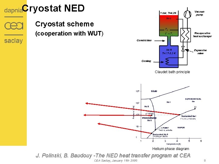
Cryostat NED Cryostat scheme (cooperation with WUT) Claudet bath principle Helium phase diagram J. Polinski, B. Baudouy -The NED heat transfer program at CEA Saclay, January 11 th 2008 8
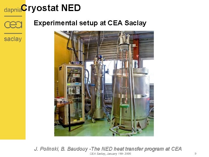
Cryostat NED Experimental setup at CEA Saclay J. Polinski, B. Baudouy -The NED heat transfer program at CEA Saclay, January 11 th 2008 9
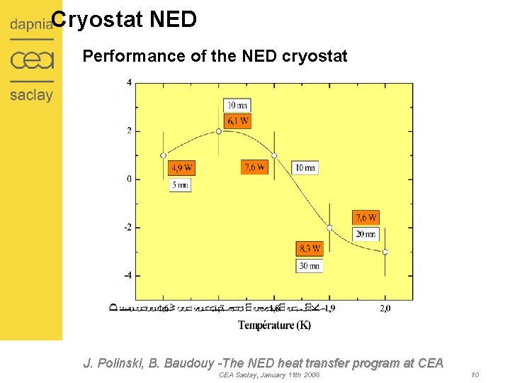
Cryostat NED Performance of the NED cryostat J. Polinski, B. Baudouy -The NED heat transfer program at CEA Saclay, January 11 th 2008 10
Contest • Motivations of the program • Cryostat NED • Conventional insulation (Kapton) – Saclay sample • Ceramic (innovative) insulation – KEK sample • RAL conventional insulation – drum method • Technical solutions investigation • Conclusions J. Polinski, B. Baudouy -The NED heat transfer program at CEA Saclay, January 11 th 2008 11
Conventional Kapton insulation Insulation description • • • 1 st layer: Kapton 200 HN (50 μm x 11 mm) in 2 wrappings (no overlap) 2 nd layer: Kapton 270 LCI (71 μ m x 11 mm) with a 2 mm gap Thermally treatment at 170 o. C for polymerisation J. Polinski, B. Baudouy -The NED heat transfer program at CEA Saclay, January 11 th 2008 12
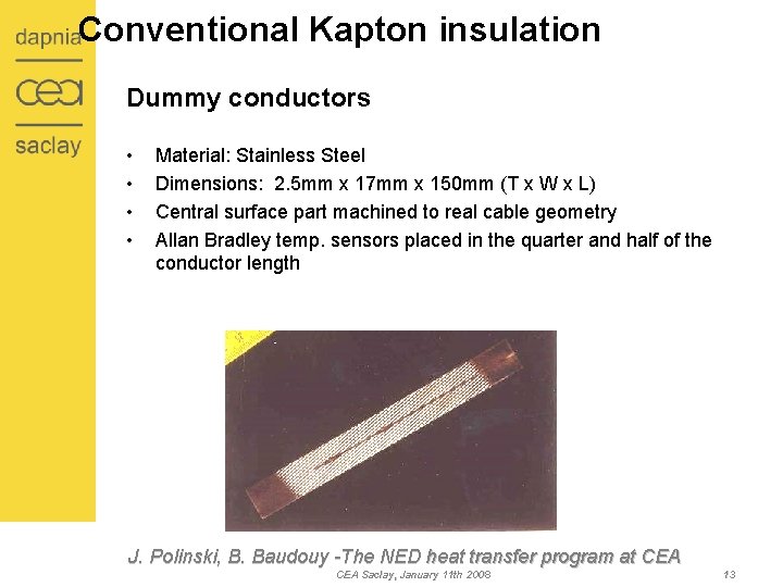
Conventional Kapton insulation Dummy conductors • • Material: Stainless Steel Dimensions: 2. 5 mm x 17 mm x 150 mm (T x W x L) Central surface part machined to real cable geometry Allan Bradley temp. sensors placed in the quarter and half of the conductor length J. Polinski, B. Baudouy -The NED heat transfer program at CEA Saclay, January 11 th 2008 13
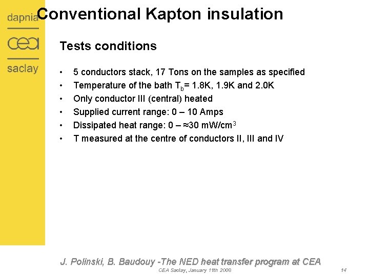
Conventional Kapton insulation Tests conditions • • • 5 conductors stack, 17 Tons on the samples as specified Temperature of the bath Tb= 1. 8 K, 1. 9 K and 2. 0 K Only conductor III (central) heated Supplied current range: 0 – 10 Amps Dissipated heat range: 0 – ≈30 m. W/cm 3 T measured at the centre of conductors II, III and IV J. Polinski, B. Baudouy -The NED heat transfer program at CEA Saclay, January 11 th 2008 14
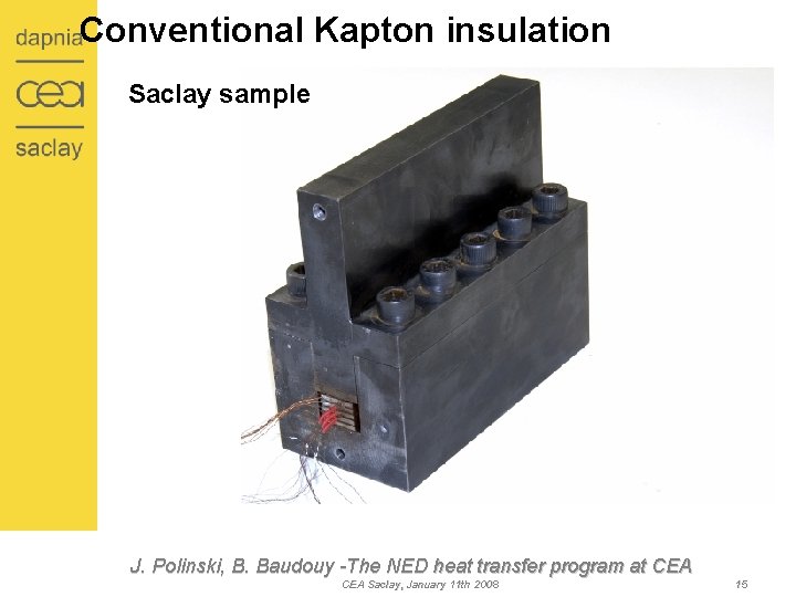
Conventional Kapton insulation Saclay sample J. Polinski, B. Baudouy -The NED heat transfer program at CEA Saclay, January 11 th 2008 15
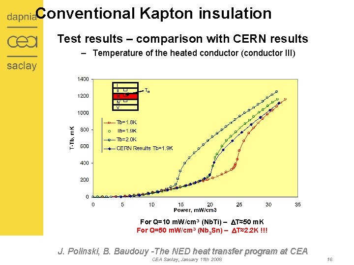
Conventional Kapton insulation Test results – comparison with CERN results – Temperature of the heated conductor (conductor III) I II IV V TIII For Q=10 m. W/cm 3 (Nb. Ti) – DT≈50 m. K For Q=50 m. W/cm 3 (Nb 3 Sn) – DT≈2. 2 K !!! J. Polinski, B. Baudouy -The NED heat transfer program at CEA Saclay, January 11 th 2008 16
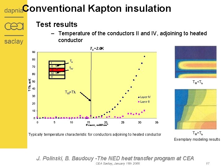
Conventional Kapton insulation Test results – Temperature of the conductors II and IV, adjoining to heated conductor Tb=2. 0 K I II IV V TII TIV TIII<Tl TIII=Tl Typically temperature characteristic for conductors adjoining to heated conductor TIII>Tl Exemplary modeling results J. Polinski, B. Baudouy -The NED heat transfer program at CEA Saclay, January 11 th 2008 17
Contest • Motivations of the program • Cryostat NED • Conventional insulation (Kapton) – Saclay sample • Ceramic (innovative) insulation – KEK sample • RAL conventional insulation – drum method • Technical solutions investigation • Conclusions J. Polinski, B. Baudouy -The NED heat transfer program at CEA Saclay, January 11 th 2008 18
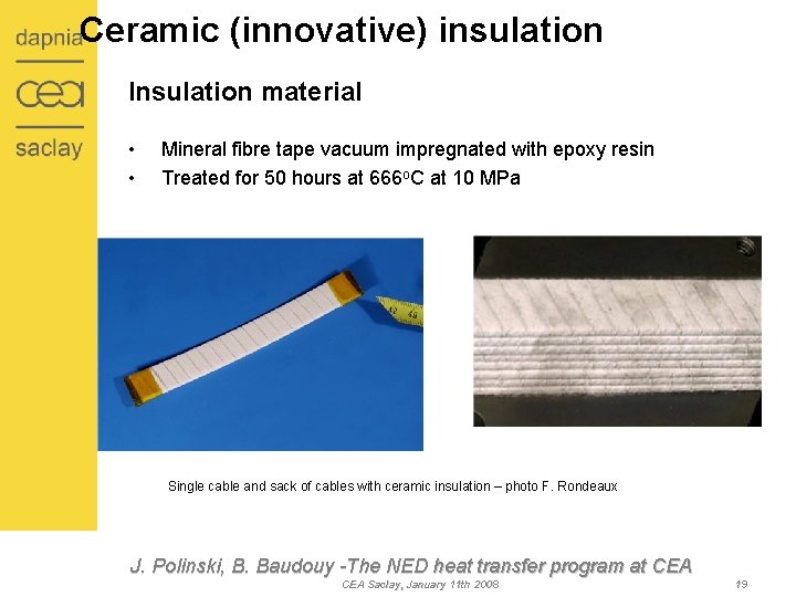
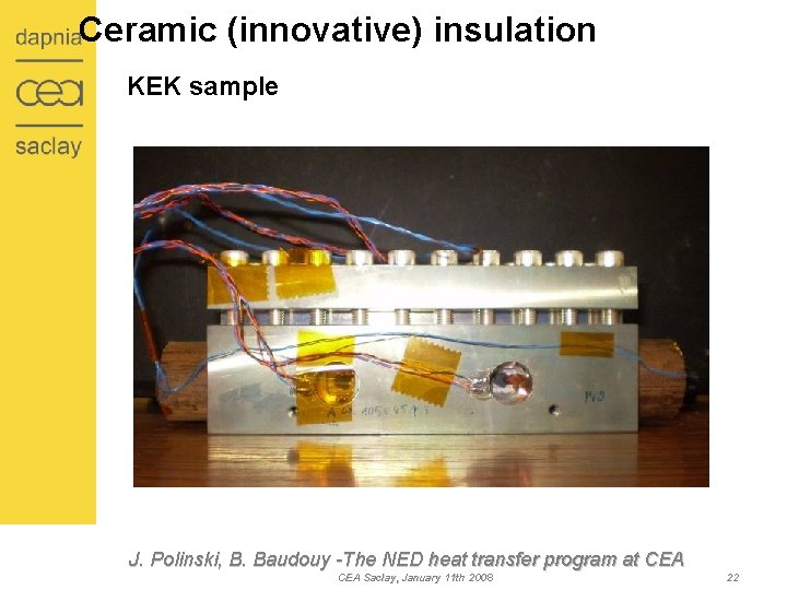
Ceramic (innovative) insulation Insulation material • • Mineral fibre tape vacuum impregnated with epoxy resin Treated for 50 hours at 666 o. C at 10 MPa Single cable and sack of cables with ceramic insulation – photo F. Rondeaux J. Polinski, B. Baudouy -The NED heat transfer program at CEA Saclay, January 11 th 2008 19
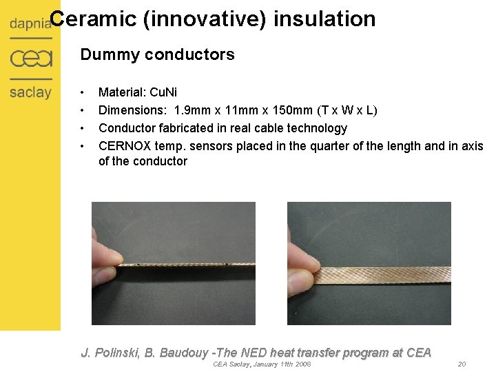
Ceramic (innovative) insulation Dummy conductors • • Material: Cu. Ni Dimensions: 1. 9 mm x 11 mm x 150 mm (T x W x L) Conductor fabricated in real cable technology CERNOX temp. sensors placed in the quarter of the length and in axis of the conductor J. Polinski, B. Baudouy -The NED heat transfer program at CEA Saclay, January 11 th 2008 20
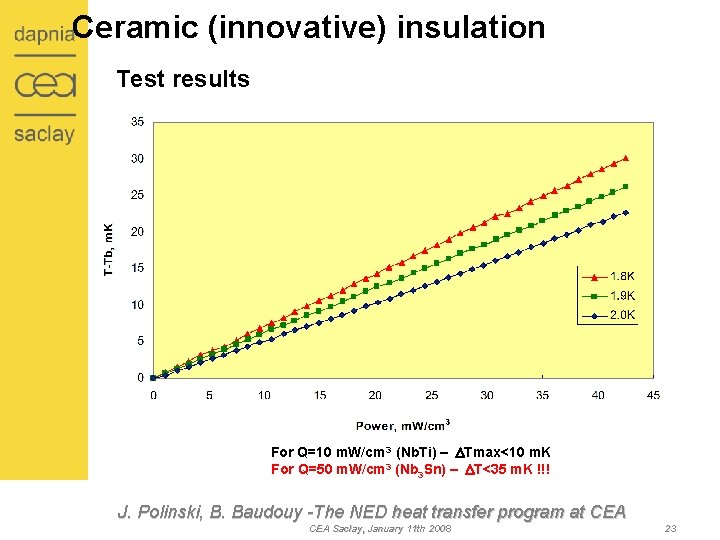
Ceramic (innovative) insulation Test condition • • • 10 MPa on the samples as specified Temperature of the bath Tb= 1. 8 K, 1. 9 K and 2. 0 K All conductors heated Supplied current range: 0 – 10 Amps Dissipated heat range: 0 – ≈42 m. W/cm 3 Temperature measured on the central conductor J. Polinski, B. Baudouy -The NED heat transfer program at CEA Saclay, January 11 th 2008 21
Ceramic (innovative) insulation KEK sample J. Polinski, B. Baudouy -The NED heat transfer program at CEA Saclay, January 11 th 2008 22
Ceramic (innovative) insulation Test results For Q=10 m. W/cm 3 (Nb. Ti) – DTmax<10 m. K For Q=50 m. W/cm 3 (Nb 3 Sn) – DT<35 m. K !!! J. Polinski, B. Baudouy -The NED heat transfer program at CEA Saclay, January 11 th 2008 23
Contest • Motivations of the program • Cryostat NED • Conventional insulation (Kapton) – Saclay sample • Ceramic (innovative) insulation – KEK sample • RAL conventional insulation – drum method • Technical solutions investigation • Conclusions J. Polinski, B. Baudouy -The NED heat transfer program at CEA Saclay, January 11 th 2008 24
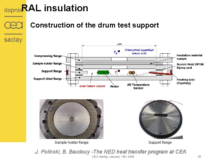
RAL insulation Construction of the drum test support Sample holder flange Support flange J. Polinski, B. Baudouy -The NED heat transfer program at CEA Saclay, January 11 th 2008 25
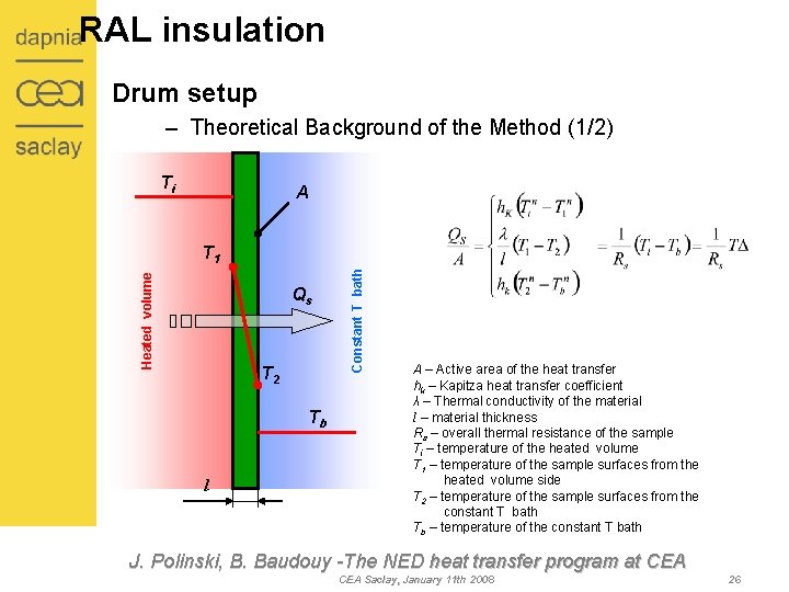
RAL insulation Drum setup – Theoretical Background of the Method (1/2) Ti A Qs T 2 Tb l Constant T bath Heated volume T 1 A – Active area of the heat transfer hk – Kapitza heat transfer coefficient λ – Thermal conductivity of the material l – material thickness Rs – overall thermal resistance of the sample Ti – temperature of the heated volume T 1 – temperature of the sample surfaces from the heated volume side T 2 – temperature of the sample surfaces from the constant T bath Tb – temperature of the constant T bath J. Polinski, B. Baudouy -The NED heat transfer program at CEA Saclay, January 11 th 2008 26
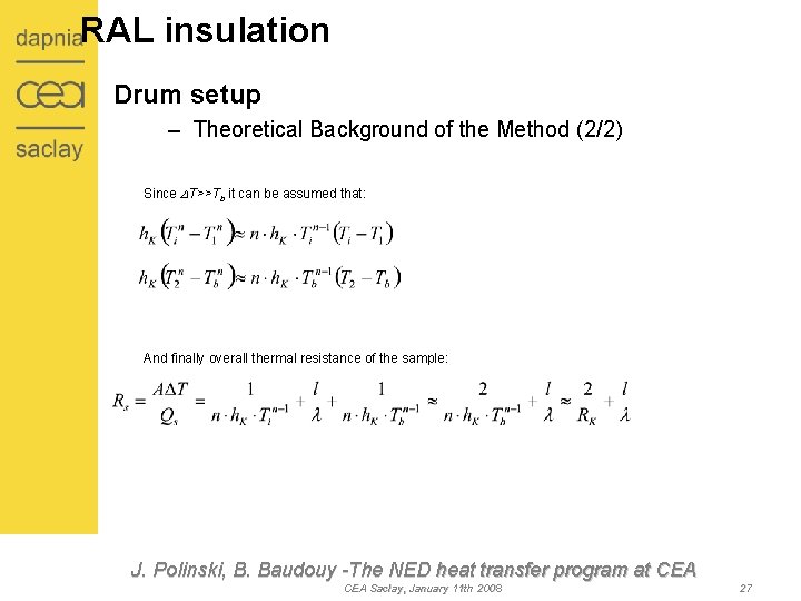
RAL insulation Drum setup – Theoretical Background of the Method (2/2) Since DT>>Tb it can be assumed that: And finally overall thermal resistance of the sample: J. Polinski, B. Baudouy -The NED heat transfer program at CEA Saclay, January 11 th 2008 27
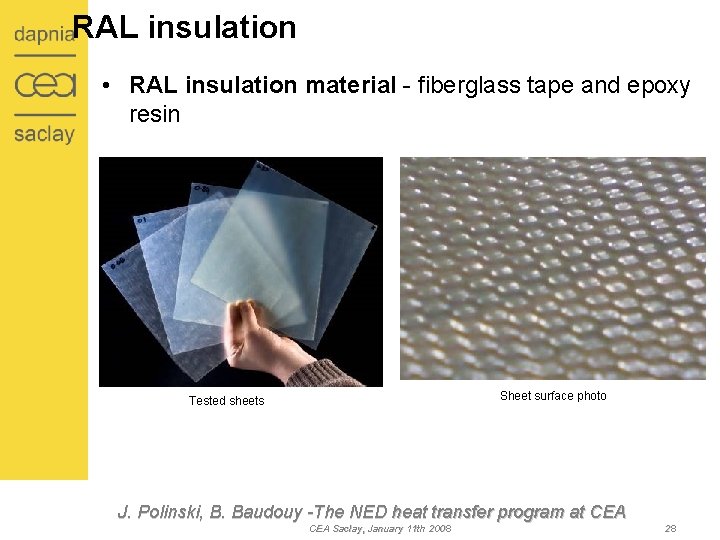
RAL insulation • RAL insulation material - fiberglass tape and epoxy resin Sheet surface photo Tested sheets J. Polinski, B. Baudouy -The NED heat transfer program at CEA Saclay, January 11 th 2008 28
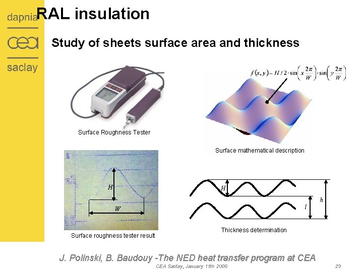
RAL insulation Study of sheets surface area and thickness Surface Roughness Tester Surface mathematical description H H h l W Surface roughness tester result Thickness determination J. Polinski, B. Baudouy -The NED heat transfer program at CEA Saclay, January 11 th 2008 29
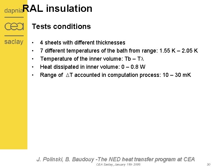
RAL insulation Tests conditions • • • 4 sheets with different thicknesses 7 different temperatures of the bath from range: 1. 55 K – 2. 05 K Temperature of the inner volume: Tb – Tl Heat dissipated in inner volume: 0 – 0. 8 W Range of DT accounted in computation process: 10 – 30 m. K J. Polinski, B. Baudouy -The NED heat transfer program at CEA Saclay, January 11 th 2008 30
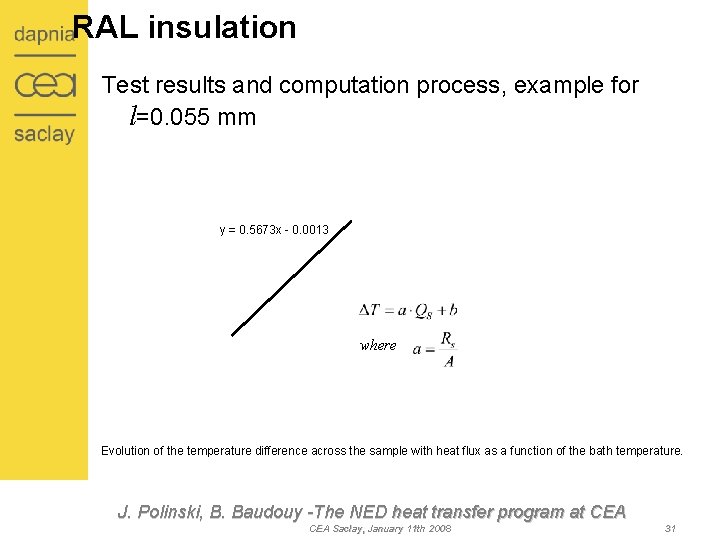
RAL insulation Test results and computation process, example for l=0. 055 mm y = 0. 5673 x - 0. 0013 where Evolution of the temperature difference across the sample with heat flux as a function of the bath temperature. J. Polinski, B. Baudouy -The NED heat transfer program at CEA Saclay, January 11 th 2008 31
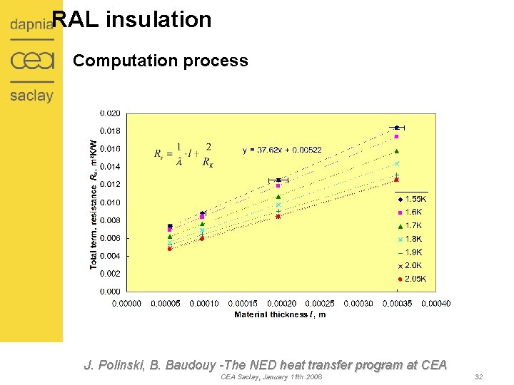
RAL insulation Computation process J. Polinski, B. Baudouy -The NED heat transfer program at CEA Saclay, January 11 th 2008 32
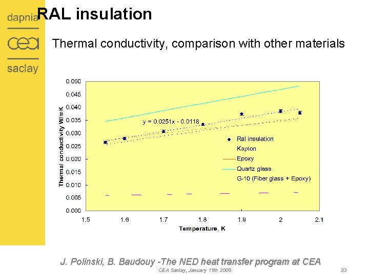
RAL insulation Thermal conductivity, comparison with other materials J. Polinski, B. Baudouy -The NED heat transfer program at CEA Saclay, January 11 th 2008 33
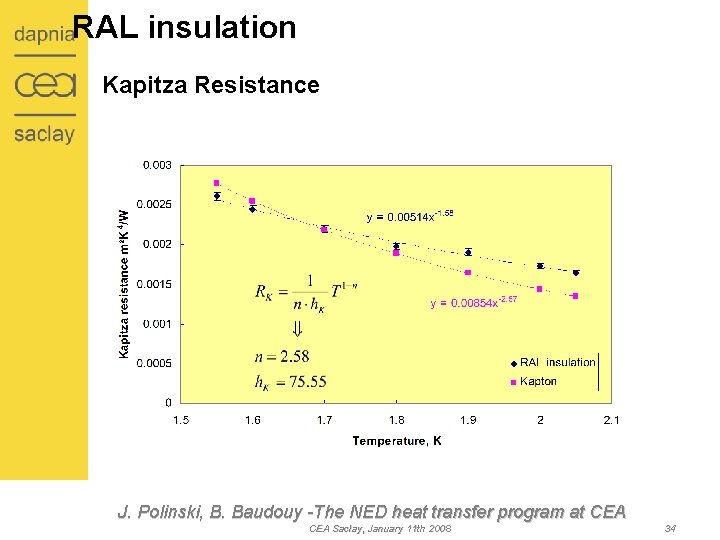
RAL insulation Kapitza Resistance J. Polinski, B. Baudouy -The NED heat transfer program at CEA Saclay, January 11 th 2008 34
Contest • Motivations of the program • Cryostat NED • Conventional insulation (Kapton) – Saclay sample • Ceramic (innovative) insulation – KEK sample • RAL conventional insulation – drum method • Technical solutions investigation • Conclusions J. Polinski, B. Baudouy -The NED heat transfer program at CEA Saclay, January 11 th 2008 35
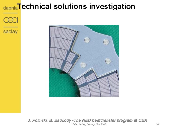
Technical solutions investigation J. Polinski, B. Baudouy -The NED heat transfer program at CEA Saclay, January 11 th 2008 36
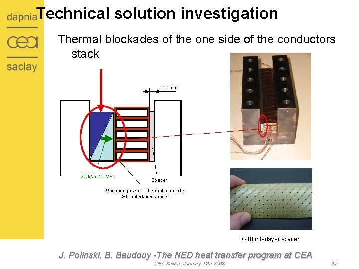
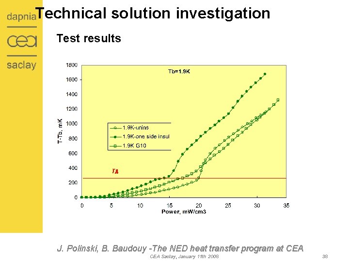
Technical solution investigation Thermal blockades of the one side of the conductors stack 0. 9 mm 20 k. N ≈10 MPa Spacer Vacuum grease – thermal blockade G 10 interlayer spacer J. Polinski, B. Baudouy -The NED heat transfer program at CEA Saclay, January 11 th 2008 37
Technical solution investigation Test results Tl J. Polinski, B. Baudouy -The NED heat transfer program at CEA Saclay, January 11 th 2008 38
Contest • Motivations of the program • Cryostat NED • Conventional insulation (Kapton) – Saclay sample • Ceramic (innovative) insulation – KEK sample • RAL conventional insulation – drum method • Technical solution study • Conclusions J. Polinski, B. Baudouy -The NED heat transfer program at CEA Saclay, January 11 th 2008 39
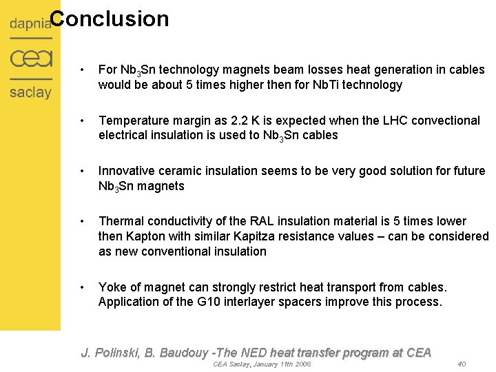
Conclusion • For Nb 3 Sn technology magnets beam losses heat generation in cables would be about 5 times higher then for Nb. Ti technology • Temperature margin as 2. 2 K is expected when the LHC convectional electrical insulation is used to Nb 3 Sn cables • Innovative ceramic insulation seems to be very good solution for future Nb 3 Sn magnets • Thermal conductivity of the RAL insulation material is 5 times lower then Kapton with similar Kapitza resistance values – can be considered as new conventional insulation • Yoke of magnet can strongly restrict heat transport from cables. Application of the G 10 interlayer spacers improve this process. J. Polinski, B. Baudouy -The NED heat transfer program at CEA Saclay, January 11 th 2008 40
Thank you for your attention J. Polinski, B. Baudouy -The NED heat transfer program at CEA Saclay, January 11 th 2008 41