
NCSX TF Coil FDR 81205 Michael Kalish Joe








- Slides: 109
NCSX TF Coil FDR 8/12/05 Michael Kalish Joe Rushinski Len Myatt 1
Outline NCSX • • • Requirements Design Review Issues / Chits Analysis and Test Fabrication Summary NCSX TF Coil FDR 8/12/05 2
Requirements NCSX • The TF coils will be designed to meet the requirements of all the reference scenarios. [Ref. GRD Section 3. 2. 1. 5. 3. 3. 2] – – 1. 7 T Ohmic Scenario: 1. 7 T for 0. 44 seconds , 120 k. A Ip 1. 7 T High Beta Scenario: 1. 7 T for 0. 44 seconds , 175 k. A Ip 2 T High Beta Scenario: 2 T for. 20 seconds, 200 k. A Ip 320 k. A Ohmic Scenario: 1. 7 T for 0. 51 seconds, 320 k. A Ip 15 minute repetition interval between pulses – The TF coils shall be designed to provide a self-field of 0. 5 T at 1. 4 m with the current waveform defined for the 0. 5 T TF Scenario defined in Section A. 3. 2 of the GRD. • Design Life – 13, 000 cycles per year – 130, 000 cycles per lifetime – 10% of lifetime or 13, 000 cycles for. 5 Tesla operation NCSX TF Coil FDR 8/12/05 3
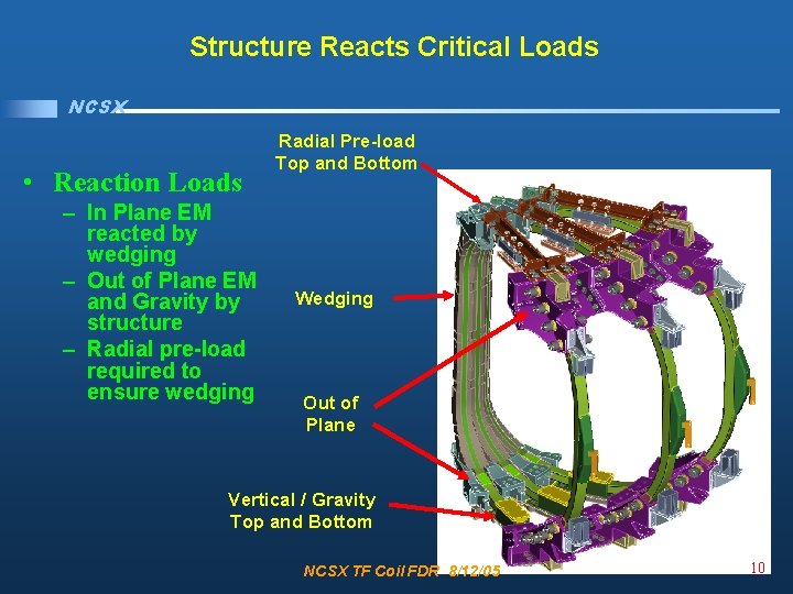
Requirements NCSX • Reaction Loads – In Plane EM reacted by wedging – Out of Plane EM and Gravity by structure – Radial pre-load required to ensure wedging • Tolerance / Location – Global requirement is that toroidal flux in island regions shall not exceed 10% – In plane installed perturbations less than +/- 3 mm inboard and +/- 6 mm outboard – Out of plane installed perturbations less than +/- 3 mm – Leads and Transitions must have a less than 1% effect on toroidal flux in island regions – Shall be up-down symmetric – Mid plane shall be aligned horizontally with the modular coils at 80 K NCSX TF Coil FDR 8/12/05 4
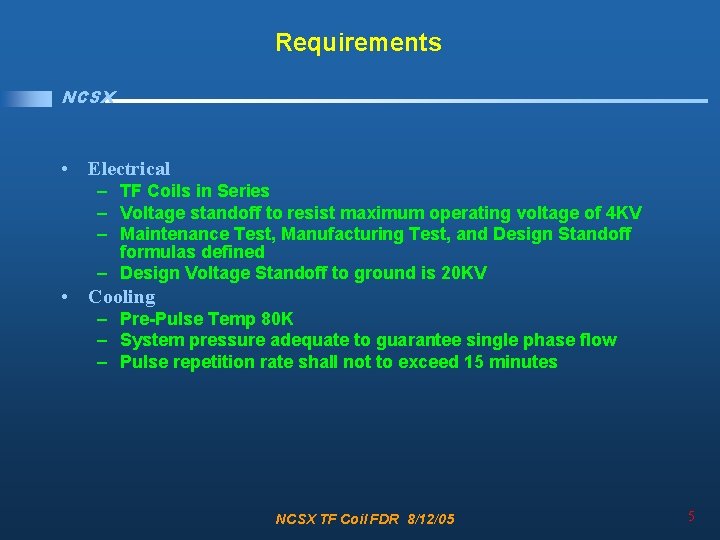
Requirements NCSX • Electrical – TF Coils in Series – Voltage standoff to resist maximum operating voltage of 4 KV – Maintenance Test, Manufacturing Test, and Design Standoff formulas defined – Design Voltage Standoff to ground is 20 KV • Cooling – Pre-Pulse Temp 80 K – System pressure adequate to guarantee single phase flow – Pulse repetition rate shall not to exceed 15 minutes NCSX TF Coil FDR 8/12/05 5
Design NCSX • Requirements • Design – – • • Overall Design PDR Design Upgrades Interference Evaluation Insulation Scheme Review Issues / Chits Analysis and Test Fabrication Summary NCSX TF Coil FDR 8/12/05 6
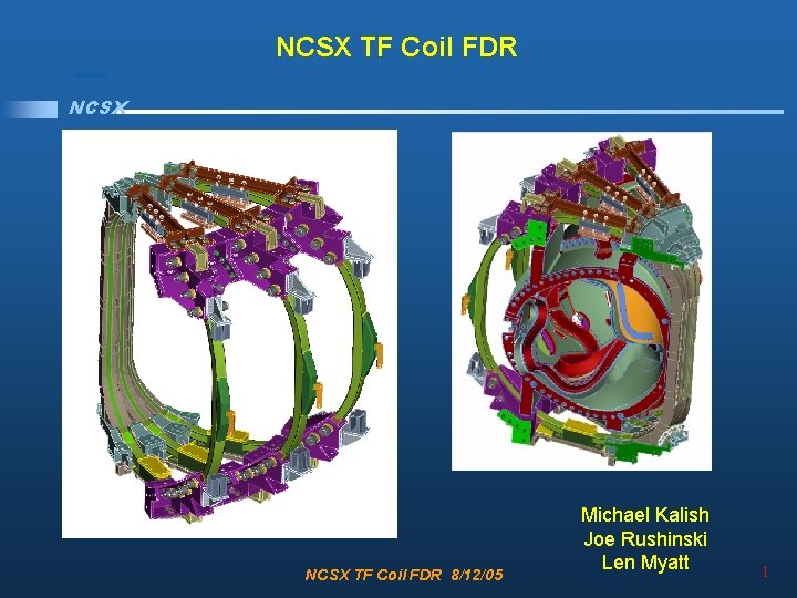
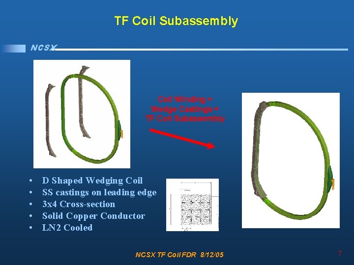
TF Coil Subassembly NCSX Coil Winding + Wedge Castings = TF Coil Subassembly • • • D Shaped Wedging Coil SS castings on leading edge 3 x 4 Cross-section Solid Copper Conductor LN 2 Cooled NCSX TF Coil FDR 8/12/05 7
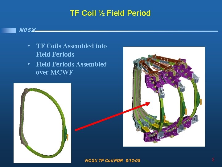
TF Coil ½ Field Period NCSX • TF Coils Assembled into Field Periods • Field Periods Assembled over MCWF NCSX TF Coil FDR 8/12/05 8
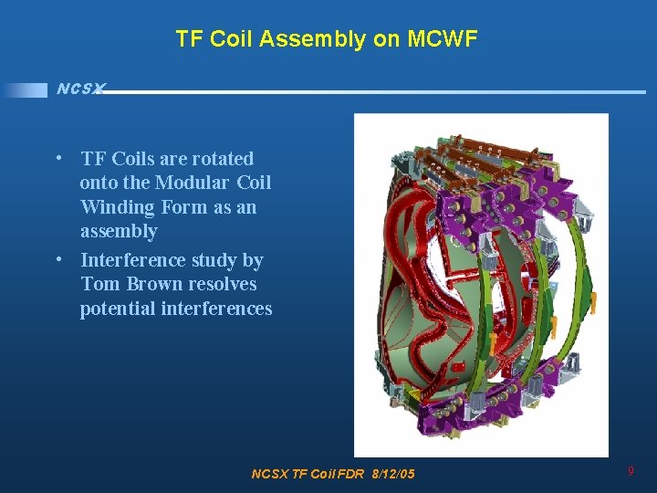
TF Coil Assembly on MCWF NCSX • TF Coils are rotated onto the Modular Coil Winding Form as an assembly • Interference study by Tom Brown resolves potential interferences NCSX TF Coil FDR 8/12/05 9
Structure Reacts Critical Loads NCSX • Reaction Loads – In Plane EM reacted by wedging – Out of Plane EM and Gravity by structure – Radial pre-load required to ensure wedging Radial Pre-load Top and Bottom Wedging Out of Plane Vertical / Gravity Top and Bottom NCSX TF Coil FDR 8/12/05 10
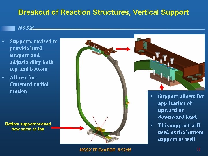
Breakout of Reaction Structures, Vertical Support NCSX • Supports revised to provide hard support and adjustability both top and bottom • Allows for Outward radial motion • Support allows for application of upward or downward load. • This support will used as the bottom support as well Bottom support revised now same as top NCSX TF Coil FDR 8/12/05 11
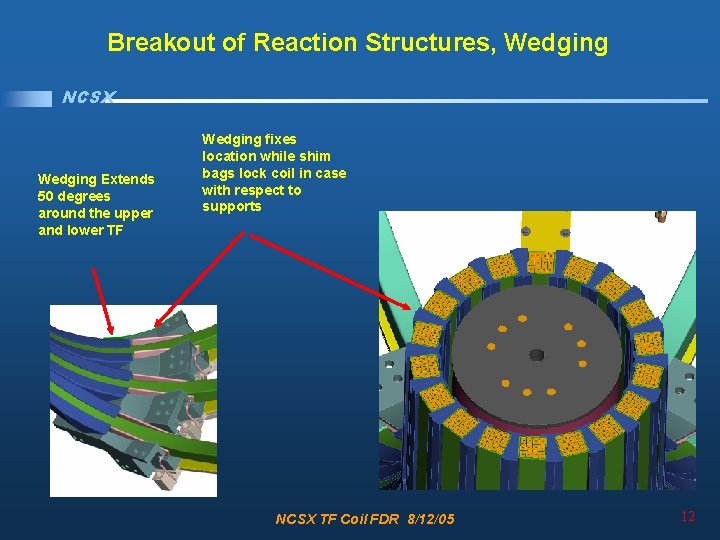
Breakout of Reaction Structures, Wedging NCSX Wedging Extends 50 degrees around the upper and lower TF Wedging fixes location while shim bags lock coil in case with respect to supports NCSX TF Coil FDR 8/12/05 12
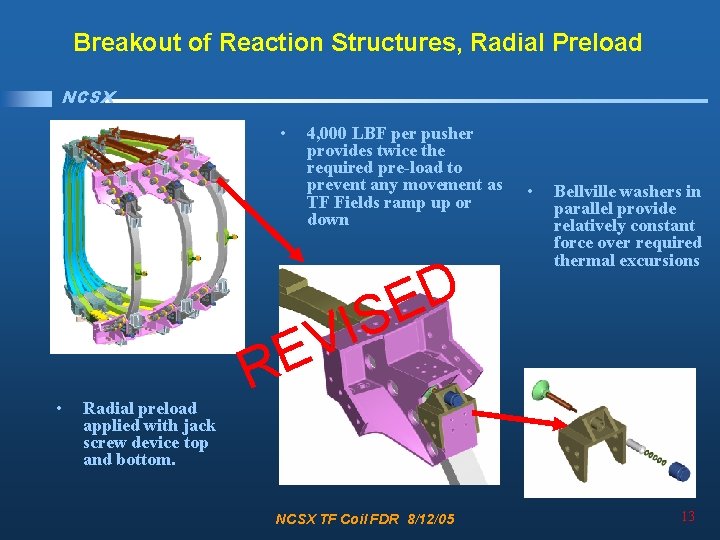
Breakout of Reaction Structures, Radial Preload NCSX • 4, 000 LBF per pusher provides twice the required pre-load to prevent any movement as TF Fields ramp up or down D E IS • Radial preload applied with jack screw device top and bottom. • Bellville washers in parallel provide relatively constant force over required thermal excursions V E R NCSX TF Coil FDR 8/12/05 13
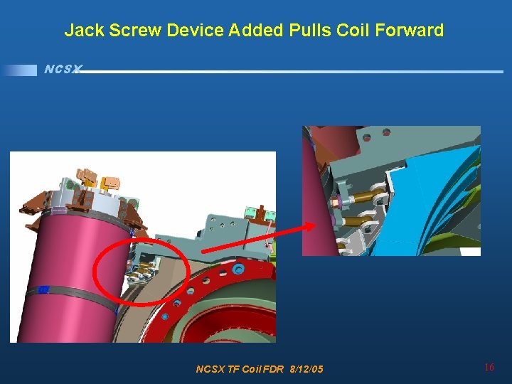
Jack Screw Device Added Pulls Coil Forward NCSX Bellville washers ensure constant 4000 lbf load NCSX TF Coil FDR 8/12/05 14
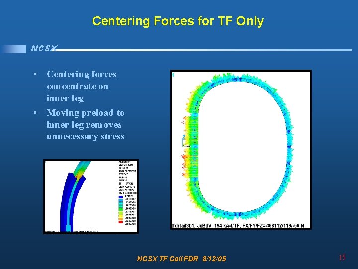
Centering Forces for TF Only NCSX • Centering forces concentrate on inner leg • Moving preload to inner leg removes unnecessary stress NCSX TF Coil FDR 8/12/05 15
Jack Screw Device Added Pulls Coil Forward NCSX TF Coil FDR 8/12/05 16
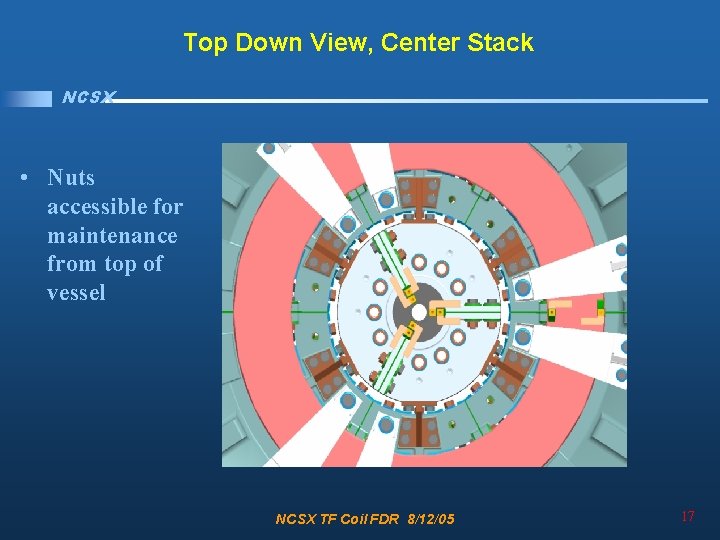
Top Down View, Center Stack NCSX • Nuts accessible for maintenance from top of vessel NCSX TF Coil FDR 8/12/05 17
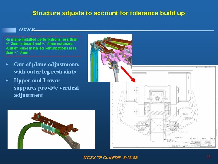
Structure adjusts to account for tolerance build up NCSX • In plane installed perturbations less than +/- 3 mm inboard and +/- 6 mm outboard • Out of plane installed perturbations less than +/- 3 mm • Out of plane adjustments with outer leg restraints • Upper and Lower supports provide vertical adjustment NCSX TF Coil FDR 8/12/05 18
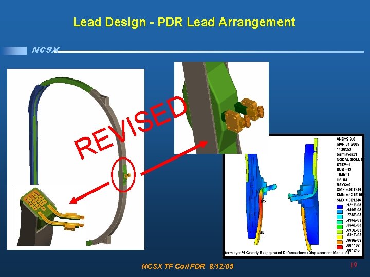
Lead Design - PDR Lead Arrangement NCSX D E S I V E R NCSX TF Coil FDR 8/12/05 19
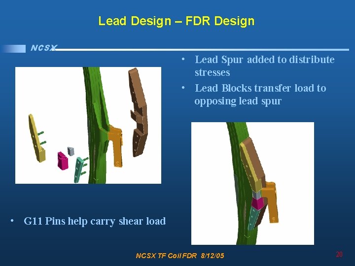
Lead Design – FDR Design NCSX • Lead Spur added to distribute stresses • Lead Blocks transfer load to opposing lead spur • G 11 Pins help carry shear load NCSX TF Coil FDR 8/12/05 20
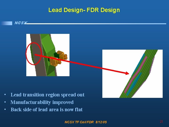
Lead Design- FDR Design NCSX • Lead transition region spread out • Manufacturability improved • Back side of lead area is now flat NCSX TF Coil FDR 8/12/05 21
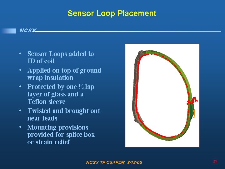
Sensor Loop Placement NCSX • Sensor Loops added to ID of coil • Applied on top of ground wrap insulation • Protected by one ½ lap layer of glass and a Teflon sleeve • Twisted and brought out near leads • Mounting provisions provided for splice box or strain relief NCSX TF Coil FDR 8/12/05 22
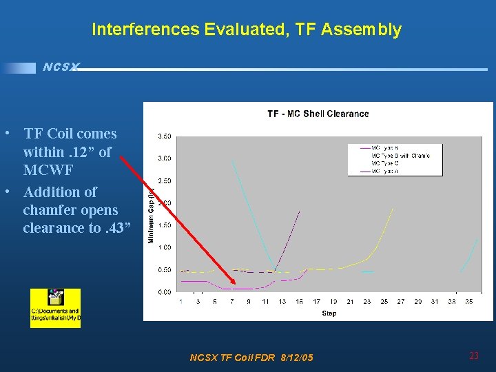
Interferences Evaluated, TF Assembly NCSX • TF Coil comes within. 12” of MCWF • Addition of chamfer opens clearance to. 43” NCSX TF Coil FDR 8/12/05 23
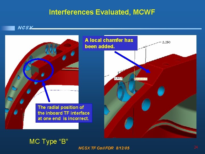
Interferences Evaluated, MCWF NCSX A local chamfer has been added. The radial position of the inboard TF interface at one end is incorrect. MC Type “B” NCSX TF Coil FDR 8/12/05 24
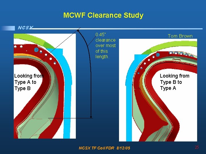
MCWF Clearance Study NCSX 0. 45” clearance over most of this length. Tom Brown Looking from Type B to Type A Looking from Type A to Type B NCSX TF Coil FDR 8/12/05 25
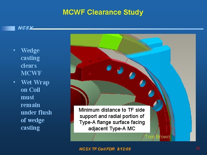
MCWF Clearance Study NCSX • Wedge casting clears MCWF • Wet Wrap on Coil must remain under flush of wedge casting Minimum distance to TF side support and radial portion of Type-A flange surface facing adjacent Type-A MC Tom Brown NCSX TF Coil FDR 8/12/05 26
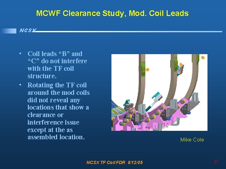
MCWF Clearance Study, Mod. Coil Leads NCSX • Coil leads “B” and “C” do not interfere with the TF coil structure. • Rotating the TF coil around the mod coils did not reveal any locations that show a clearance or interference issue except at the as assembled location. NCSX TF Coil FDR 8/12/05 Mike Cole 27
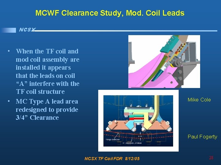
MCWF Clearance Study, Mod. Coil Leads NCSX • When the TF coil and mod coil assembly are installed it appears that the leads on coil “A” interfere with the TF coil structure • MC Type A lead area redesigned to provide 3/4” Clearance Mike Cole Paul Fogerty NCSX TF Coil FDR 8/12/05 28
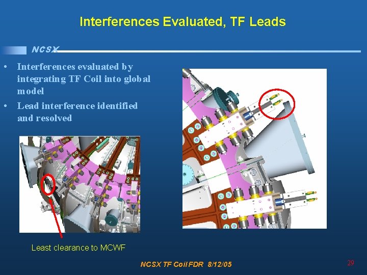
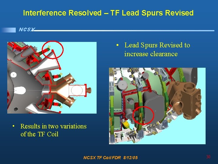
Interferences Evaluated, TF Leads NCSX • Interferences evaluated by integrating TF Coil into global model • Lead interference identified and resolved Least clearance to MCWF NCSX TF Coil FDR 8/12/05 29
Interference Resolved – TF Lead Spurs Revised NCSX • Lead Spurs Revised to increase clearance • Results in two variations of the TF Coil NCSX TF Coil FDR 8/12/05 30
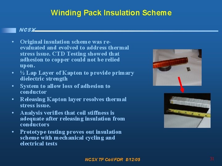
Winding Pack Insulation Scheme NCSX • Original insulation scheme was reevaluated and evolved to address thermal stress issue. CTD Testing showed that adhesion to copper could not be relied upon. • ½ Lap Layer of Kapton to provide primary dielectric strength • System to allow loss of adhesion to conductor • Releasing Kapton layer resolves thermal stress issue. • Analysis verifies that coil stiffness is adequate after releasing insulation from conductors • Prototype testing proves out insulation scheme with mechanical cycling and electrical tests NCSX TF Coil FDR 8/12/05 31
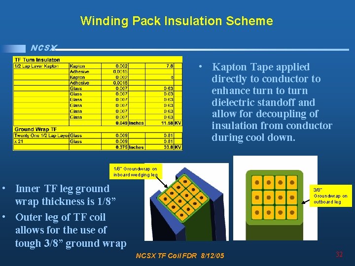
Winding Pack Insulation Scheme NCSX • Kapton Tape applied directly to conductor to enhance turn to turn dielectric standoff and allow for decoupling of insulation from conductor during cool down. 1/8” Groundwrap on inboard wedging leg • Inner TF leg ground wrap thickness is 1/8” • Outer leg of TF coil allows for the use of tough 3/8” ground wrap 3/8” Groundwrap on outboard leg NCSX TF Coil FDR 8/12/05 32
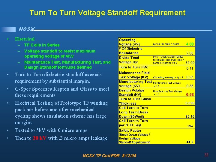
Turn To Turn Voltage Standoff Requirement NCSX • Electrical – TF Coils in Series – Voltage standoff to resist maximum operating voltage of 4 KV – Maintenance Test, Manufacturing Test, and Design Standoff formulas defined • • • Turn to Turn dielectric standoff exceeds requirement by substantial margin. C-Specifies Kapton and Glass to meet these requirements Electrical Testing of Prototype TF winding pack bar before and after mechanical cycling shows insulation scheme has large margins. Tested to 5 k. V with 0 micro amps Then to 20 k. V with. 3 micro amps leakage NCSX TF Coil FDR 8/12/05 33
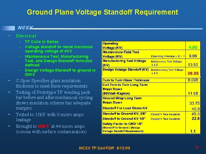
Ground Plane Voltage Standoff Requirement NCSX • Electrical – TF Coils in Series – Voltage standoff to resist maximum operating voltage of 4 KV – Maintenance Test, Manufacturing Test, and Design Standoff formulas defined – Design Voltage Standoff to ground is 20 KV • • C-Specifies glass insulation thickness to meet these requirements Testing of Prototype TF winding pack bar before and after mechanical cycling shows insulation scheme has adequate margins. Tested to 15 k. V with 0 micro amps leakage Brought to 60 k. V at 44 micro amps (corona with surface contamination) NCSX TF Coil FDR 8/12/05 34
Review Issues / Chits NCSX • Requirements • Design • • Review Issues / Chits Analysis and Test Fabrication Summary NCSX TF Coil FDR 8/12/05 35
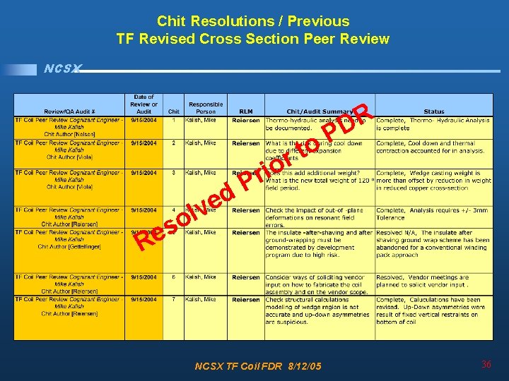
Chit Resolutions / Previous TF Revised Cross Section Peer Review NCSX s e R r P d e v l o t r io R D P o NCSX TF Coil FDR 8/12/05 36
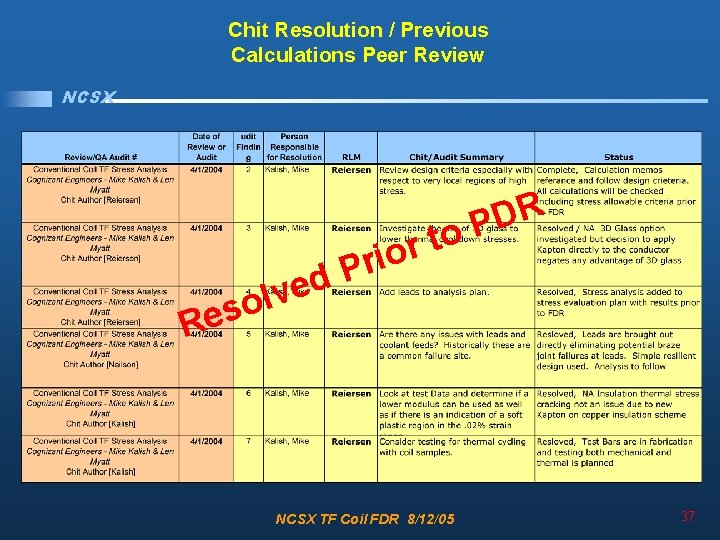
Chit Resolution / Previous Calculations Peer Review NCSX o t r o i r P d e R D P R v l o es NCSX TF Coil FDR 8/12/05 37
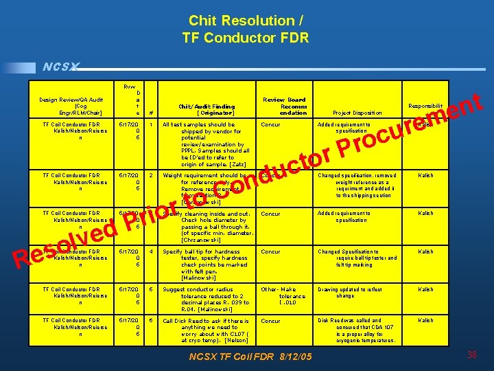
Chit Resolution / TF Conductor FDR NCSX Rvw Design Review/QA Audit [Cog Engr/RLM/Chair] D a t e # TF Coil Conductor FDR Kalish/Nelson/Reierse n 5/17/20 0 5 1 TF Coil Conductor FDR Kalish/Nelson/Reierse n 5/17/20 0 5 2 o s Re 5/17/20 0 5 Review Board Recomm endation All test samples should be shipped by vendor for potential review/examination by PPPL. Samples should all be ID'ed to refer to origin of sample. [Zatz] Concur Weight requirement should be for reference only. Remove requirement from section 3. [Chrzanowski] Concur o t r rio P d lve TF Coil Conductor FDR Kalish/Nelson/Reierse n Chit/Audit Finding [Originator] Project Disposition r u c ro Added requirement to specification P r o t c u d n Co t n e em Responsibilit y Kalish Changed specification, removed weight reference as a requriment and added it to the shipping section Kalish 3 Specify cleaning inside and out. Concur Check hole diameter by passing a ball through it. (of specific min. diameter. [Chrzanowski] Added requirement to specification Kalish TF Coil Conductor FDR Kalish/Nelson/Reierse n 5/17/20 0 5 4 Specify ball tip for hardness tester, specify hardness check points be marked with felt pen. [Malinowski] Concur Changed Specification to require ball tip tester and felt tip marking Kalish TF Coil Conductor FDR Kalish/Nelson/Reierse n 5/17/20 0 5 5 Suggest conductor radius tolerance reduced to 2 decimal places R. 039 to R. 04. [Malinowski] Other- Make tolerance I. 010 Drawing updated to reflect change Kalish TF Coil Conductor FDR Kalish/Nelson/Reierse n 5/17/20 0 5 6 Call Dick Reed to ask if there is anything we need to worry about with C 107 ( at cryo temp). [Nelson] Concur Dick Reed was called and concured that CDA 107 is a proper alloy for cryogenic temperatures. Kalish NCSX TF Coil FDR 8/12/05 38
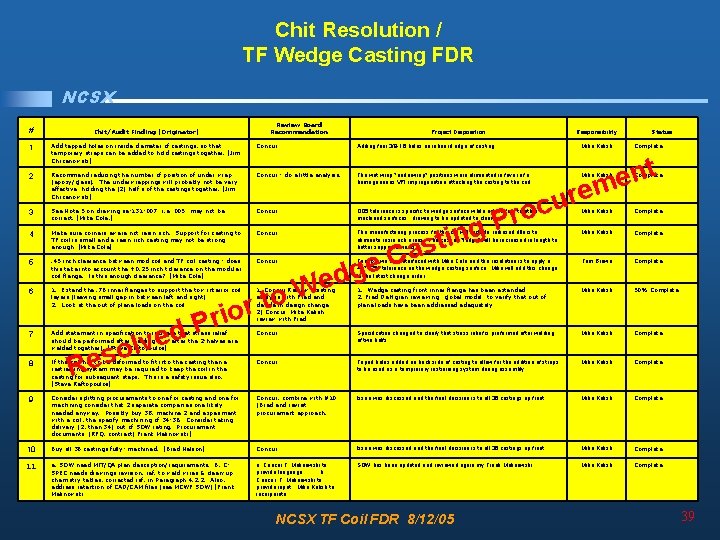
Chit Resolution / TF Wedge Casting FDR NCSX Review Board Recommendation # Chit/Audit Finding [Originator] 1 Add tapped holes on inside diameter of castings, so that temporary straps can be added to hold castings together. [Jim Chrzanowski] Concur Adding four 3/8 -16 holes on inboard edge of casting Mike Kalish 2 Recommend reducing the number of position of under wrap (epoxy/glass). The underwrappings will probably not be very effective holding the (2) half's of the castings together. [Jim Chrzanowski] Concur - do a little analysis. The wet wrap "underwrap" positions were eliminated in favor of a homogeneous VPI impreganation attaching the casting to the coil 3 See Note 5 on drawing se-131 -007 "i. e. 005" may not be correct. [Mike Cole, ] Concur t n e em 4 Make sure corners aware not resin rich. Support for casting to TF coil is small and a resin rich casting may not be strong enough. [Mike Cole] Concur 5 . 45 inch clearance between mod coil and TF coil casting - does this take into account the +0. 25 inch tolerance on the modular coil flange. Is this enough clearance? [Mike Cole] Concur 6 1. Extend the. 76 inner flanges to support the tow interior coil layers (leaving small gap in between left and right) 2. Look at the out of plane loads on the coil 7 Project Disposition Responsibility Status Complete Mike Kalish Complete . 005 tolerance is specific to wedge surface while note refers to other machined surfaces. drawing to be updated to clarify Mike Kalish Complete The manufacturing process for the coil will include radiused fillers to eliminate resin rich areas. The casting "ledge" will be increased in length to better support corners Mike Kalish Complete Tom Brown has interfaced with Mike Cole and the resolution is to apply a +0" -. 25" tolerance on the wedge casting surface. Mike will add this change to the latest change order Tom Brown Complete 1. Concur Review existing 1. Wedge casting front inner flange has been extended analysis with Fred and 2. Fred Dahlgren reviewing "global model" to verify that out of decide in design change. plane loads have been addressed adequately 2) Concur Mike Kalish review with Fred Mike Kalish 50% Complete Add statement in specification to indicate that stress relief should be performed after welding (i. e. after the 2 -halves are welded together). [Steve Raftopoulos] Concur Specification changed to clarify that stress relief is preformed after welding of two halfs Mike Kalish Complete 8 If the coil has to be deformed to fit into the casting then a restraining system may be required to keep the coil in the casting for subsequent steps. This is a safety issue also. [Steve Raftopoulos] Concur Taped holes added on back side of casting to allow for the addition of straps to be used as a temprorary restraining system during assembly Mike Kalish Complete 9 Consider splitting procurements to one for casting and one for machining consider that 2 separate companies one likely needed anyway. Possibly buy 38, machine 2 and experiment with a coil, the specify machining of 34 -36. Consider taking delivery (2, then 34) out of SOW rating. Procurement documents (RFQ, contract) Frank Malinowski] Concur, combine with #10 (Brad and revisit procurement approach. Issue was discussed and the final decision is to all 36 castings up front Mike Kalish Complete 10 Buy all 36 castings fully- machined. [Brad Nelson] Concur Issue was discussed and the final decision is to all 36 castings up front Mike Kalish Complete 11 a. SOW need MIT/QA plan description/requirements. B. CSPEC needs drawings revision, ref. to weld wires & clean-up chemistry tables, corrected ref. in Paragraph 4. 2. 2. Also, address retention of CAD/CAM files (see MCWF SOW) [Frank Malinowski a. Concur F. Malinowski to provide language b. Concur. F. Malinowski to provide input. Mike Kalish to incorporate. SOW has been updated and reviewed again my Frank Malinowski Mike Kalish Complete d e v l so r o i r P Re e W to r u c ro C e g d P g n i t s a NCSX TF Coil FDR 8/12/05 39
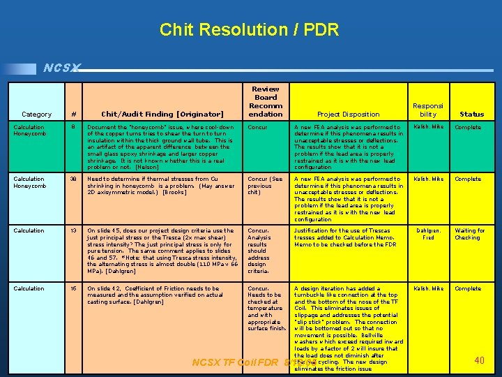
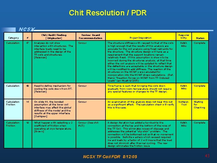
Chit Resolution / PDR NCSX Review Board Recomm endation Responsi bility # Chit/Audit Finding [Originator] Calculation Honeycomb 8 Document the "honeycomb" issue, where cool-down of the copper turns tries to shear the turn to turn insulation within the thick ground wall tube. This is an artifact of the apparent difference between the small glass epoxy shrinkage and larger copper shrinkage. It is not known whether this is a real problem or not. [Nelson] Concur A new FEA analysis was performed to determine if this phenomena results in unacceptable stresses or deflections. The results show that it is not a problem if the lead area is properly restrained as it is with the new lead configuration Kalish, Mike Complete Calculation Honeycomb 38 Need to determine if thermal stresses from Cu shrinking in honeycomb is a problem. (May answer 2 D axisymmetric model. ) [Brooks] Concur (See previous chit) A new FEA analysis was performed to determine if this phenomena results in unacceptable stresses or deflections. The results show that it is not a problem if the lead area is properly restrained as it is with the new lead configuration Kalish, Mike Complete Calculation 13 On slide 45, does our project design criteria use the just principal stress or the Tresca (2 x max shear) stress intensity? The just principal stress is only for pure tension. The same comment applies to slides 46 and 57. *Note: that using Tresca stress intensity, the alternating stress is almost double (110 MPa v 66 MPa). [Dahlgren] Concur. Analysis results should address design criteria. Justification for the use of Trescas tresses added to Calculation Memo to be checked before the FDR Calculation 15 On slide 42, Coefficient of Friction needs to be measured and the assumption verified on actual casting surface. [Dahlgren] Concur. Needs to be checked at temperature and with appropriate surface finish. A design iteration has added a turnbuckle like connection at the top and the bottom of the nose of the TF Coil. This eliminates issues of slippage and addresses the potential "slip stick" problem. The connection will be bottomed out so that no movement is possible. Bellville washers which exceed required inward loads by a factor of 2 will insure that the load does not diminish after thermal cycling. The new design eliminates the friction issue Category Project Disposition NCSX TF Coil FDR 8/12/05 Dahlgren, Fred Kalish, Mike Status Waiting for Checking Complete 40
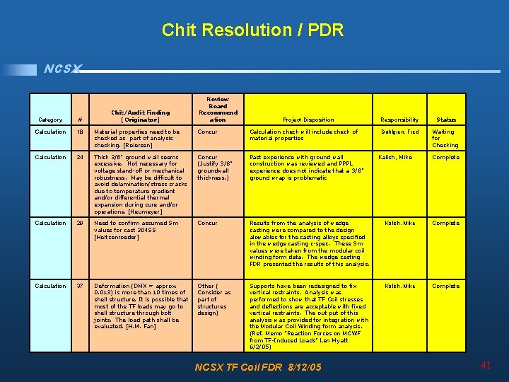
Chit Resolution / PDR NCSX Chit/Audit Finding [Originator] Review Board Recommend ation Project Disposition Responsibility Status Dahlgren, Fred Waiting for Checking Category # Calculation 18 Material properties need to be checked as part of analysis checking. [Reiersen] Concur Calculation check will include check of material properties Calculation 24 Thick 3/8" ground wall seems excessive. Not necessary for voltage stand-off or mechanical robustness. May be difficult to avoid delamination/stress cracks due to temperature gradient and/or differential thermal expansion during cure and/or operations. [Neumeyer] Concur (Justify 3/8" groundwall thickness. ) Past experience with ground wall construction was reviewed and PPPL experience does not indicate that a 3/8" ground wrap is problematic Calculation 29 Need to confirm assumed Sm values for cast 304 SS [Heitzenroeder] Concur Results from the analysis of wedge casting were compared to the design alowables for the casting alloys specified in the wedge casting c-spec. These Sm values were taken from the modular coil winding form data. The wedge casting FDR presented the results of this analysis. Kalish, Mike Complete Calculation 37 Deformation (DMX = approx. 0. 013) is more than 10 times of shell structure. It is possible that most of the TF loads may go to shell structure through bolt joints. The load path shall be evaluated. [H. M. Fan] Other ( Consider as part of structures design) Supports have been redesigned to fix vertical restraints. Analysis was performed to show that TF Coil stresses and deflections are acceptable with fixed vertical restraints. The out put of this analysis was provided for integration with the Modular Coil Winding form analysis. (Ref. Memo "Reaction Forces on MCWF from TF-Induced Loads" Len Myatt 6/2/05) Kalish, Mike Complete NCSX TF Coil FDR 8/12/05 Kalish, Mike Complete 41
Chit Resolution / PDR NCSX Chit/Audit Finding [Originator] Review Board Recommend ation Project Disposition Responsibility Status Concur Supports have been redesigned to fix vertical restraints. Analysis was performed to show that TF Coil stresses and deflections are acceptable with fixed vertical restraints. (Ref. Memo "Effects of Coil Support Concepts on TF WP Stresses" Len Myatt 5/16/05 Kalish, Mike Complete The analysis is inconsistent with the design. The design says the wedges and winding are bonded. The analysis assumed they slip. Ditto for the thickness of the ground wrap [Reiersen] Concur The analysis has been updated and rerun to provide results for both the bonded and unbonded wedge casting cases. The groundwrap thickness in the analysis model has been updated and that analysis re-run as well. (Ref Memo "Stress Analysis of the 3 x 4 Slip-Plane TF Coil with Cast SS Wedges" Len Myatt 3/7/05 Kalish, Mike Complete Design criteria should be established for friction joints. [Reiersen] Concur A design iteration has added a turnbuckle like connection at the top and the bottom of the nose of the TF Coil. This eliminates issues of slippage and addresses the potential "slip stick" problem. The connection will be bottomed out so that no movement is possible. Bellville washers which exceed required inward loads by a factor of 2 will insure that the load does not diminish after thermal cycling. The new design eliminates the friction issue Kalish, Mike Complete Category # Calculation 39 Need to assess impact of upper vertical spring support on TF stresses T deflections. [Brooks] Calculation 44 Calculation 46 NCSX TF Coil FDR 8/12/05 42
Chit Resolution / PDR NCSX Chit/Audit Finding [Originator] Review Board Recommendation Project Disposition Responsi bility Status Category # Calculation 47 Analyses do not show interaction with structures. The interface loads need to be addressed in the design of the TF coils and structures. [Reiersen] Concur The structure stiffness with respect to that of the coils is high enough that the results of this analysis are accurate for the coil analysis using fixed restraints for the structure. The structure design will have as a requirement that the support locations remain relatively fixed. If this assumption is shown to be incorrect during the structures analysis, at that time either the coil analysis will be updated to reflect that the deflections are acceptable or the structure design will be modified to add stiffness. The reaction of the structures on the MCWF were calculated for incorporation into the MCWF stress calculations. (Ref. Memo "Reaction Forces on MCWF from TF-Induced Loads" Len Myatt 6/2/05) Kalish, Mike Complete Calculation 48 Need to define mechanism for cooling the coils down from RT. [Reiersen] Concur Time frame is such that bringing the coils down gradually from room temperature should not require any special features or changes to the TF design. Kalish, Mike Complete Calculation Friction 14 On slide 44, the bonded assumption at the lower coil interface may affect the global stiffness of the model and the results at the upper interface. [Dahlgren] Concur An examination of the analysis does not bear this out as a significant effect. The calculation check will verify this is the case. Dahlgren, Fred Waiting for Checking Calculation Friction 19 What happen with selecting u 2 coefficient of friction when operating at cryo temperature. [Brown] Concur (See chit #15) A design iteration has added a turnbuckle like connection at the top and the bottom of the nose of the TF Coil. This eliminates issues of slippage and addresses the potential "slip stick" problem. The connection will be bottomed out so that no movement is possible. Bellville washers which exceed required inward loads by a factor of 2 will insure that the load does not diminish after thermal cycling. The new design eliminates the friction issue Kalish, Mike Complete NCSX TF Coil FDR 8/12/05 43
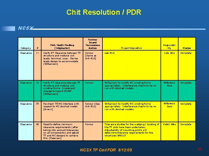
Chit Resolution / PDR NCSX Category # Chit/Audit Finding [Originator] Calculation Lead 40 Need same analysis of lead/transition regime stress. [Brooks] Calculation Lead 42 Clearance Review Board Recommenda tion Status Project Disposition Responsibility Concur A new detailed analysis of lead transition area was performed. The lead area was redesigned with lead spurs to lower stresses and the lead transition area stress analysis was repeated. (Ref. Memo "Stress Analysis of the TF Coil Terminal Design with Lead Spurs" Len Myatt 5/25/05) Kalish, Mike Complete Stresses in leads and transition region need to be addressed. [Reiersen] Concur A new detailed analysis of lead transition area was performed. The lead area was redesigned with lead spurs to lower stresses and the lead transition area stress analysis was repeated. (Ref. Memo "Stress Analysis of the TF Coil Terminal Design with Lead Spurs" Len Myatt 5/25/05) Kalish, Mike Complete 1 Are we sure that the leads at the midplane miss the NBI transition ducts and allow space for routing the coaxial bus? [Nelson] (Need to finalize TF Coil lead configuration and bus connection and re-check clearances at each coil. ) Yes. The clearances have been checked in the pro engineer model Kalish, Mike Complete Clearance 5 Look at the assembly with the TF Coils retracted to make sure there is still clearance everywhere. [Nelson] Concur A study of clearances taking into account tolerances will be presented at the FDR Kalish, Mike Complete Clearance 10 Check interference between TF Coils and MC leads. [Cole] Concur Mike Cole to check. Cole, Mike Complete NCSX TF Coil FDR 8/12/05 44
Chit Resolution / PDR NCSX Review Board Recommen dation Chit/Audit Finding [Originator] Project Disposition Responsibi lity Status Category # Clearance 11 Verify RT Clearance between TF structure and modular coil leads, terminal, coax. Revise leads design to accommodate (Williamson) Concur [Same as chit #10] see #10 Cole, Mike Complete Clearance 12 Verify RT clearance between TF structure and modular coil winding forms. Implement change to type-B MCWF. [Williamson] Concur Williamson to modify MC winding forms appropriately. Interference checks to be rerun with stocked models. Williamson, Dave Complete Clearance 20 Re-check TF/MC interface with respect to MC stocked model. [Brown] Concur (See chit #12) Williamson to modify MC winding forms appropriately. Interference checks to be rerun with stocked models. Williamson, Dave Complete Clearance 49 Need to define minimum clearance requirements (after taking into account tolerances on all components) and adjust TF and MC designs to achieve this. [Reiersen] Concur Tolerance studies for the wedging / locating of the TF coils have been undertaken. Adjustability of mounting points will determine tolerance requirements for the structures WBS 15 Kalish, Mike Complete NCSX TF Coil FDR 8/12/05 45
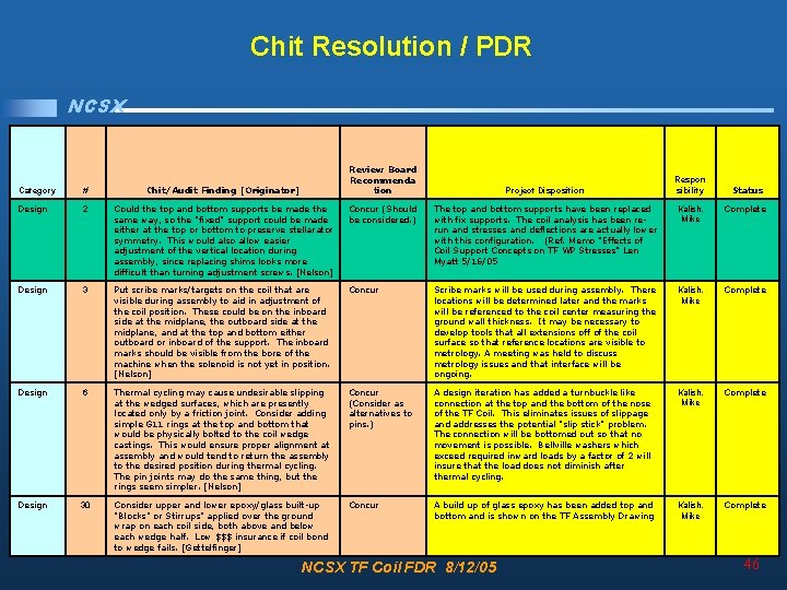
Chit Resolution / PDR NCSX Review Board Recommenda tion Respon sibility Category # Chit/Audit Finding [Originator] Design 2 Could the top and bottom supports be made the same way, so the "fixed" support could be made either at the top or bottom to preserve stellarator symmetry. This would also allow easier adjustment of the vertical location during assembly, since replacing shims looks more difficult than turning adjustment screws. [Nelson] Concur (Should be considered. ) The top and bottom supports have been replaced with fix supports. The coil analysis has been rerun and stresses and deflections are actually lower with this configuration. (Ref. Memo "Effects of Coil Support Concepts on TF WP Stresses" Len Myatt 5/16/05 Kalish, Mike Complete Design 3 Put scribe marks/targets on the coil that are visible during assembly to aid in adjustment of the coil position. These could be on the inboard side at the midplane, the outboard side at the midplane, and at the top and bottom either outboard or inboard of the support. The inboard marks should be visible from the bore of the machine when the solenoid is not yet in position. [Nelson] Concur Scribe marks will be used during assembly. There locations will be determined later and the marks will be referenced to the coil center measuring the ground wall thickness. It may be necessary to develop tools that all extensions off of the coil surface so that reference locations are visible to metrology. A meeting was held to discuss metrology issues and that interface will be ongoing. Kalish, Mike Complete Design 6 Thermal cycling may cause undesirable slipping at the wedged surfaces, which are presently located only by a friction joint. Consider adding simple G 11 rings at the top and bottom that would be physically bolted to the coil wedge castings. This would ensure proper alignment at assembly and would tend to return the assembly to the desired position during thermal cycling. The pin joints may do the same thing, but the rings seem simpler. [Nelson] Concur (Consider as alternatives to pins. ) A design iteration has added a turnbuckle like connection at the top and the bottom of the nose of the TF Coil. This eliminates issues of slippage and addresses the potential "slip stick" problem. The connection will be bottomed out so that no movement is possible. Bellville washers which exceed required inward loads by a factor of 2 will insure that the load does not diminish after thermal cycling. Kalish, Mike Complete Design 30 Consider upper and lower epoxy/glass built-up "Blocks" or Stirrups" applied over the ground wrap on each coil side, both above and below each wedge half. Low $$$ insurance if coil bond to wedge fails. [Gettelfinger] Concur A build up of glass epoxy has been added top and bottom and is shown on the TF Assembly Drawing Kalish, Mike Complete Project Disposition NCSX TF Coil FDR 8/12/05 Status 46
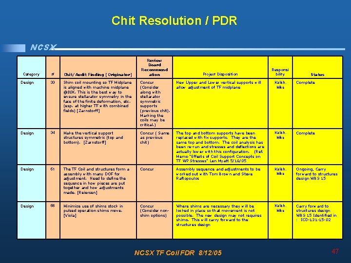
Chit Resolution / PDR NCSX Review Board Recommend ation Responsi bility # Chit/Audit Finding [Originator] Design 33 Shim coil mounting so TF Midplane is aligned with machine midplane @80 K. This is the best way to ensure stellarator symmetry in the face of the finite deformation, etc. (esp. at higher TF with combined fields) [Zarnstorff] Concur New Upper and Lower vertical supports will (Consider allow adjustment of TF midplane along with stellarator symmetric supports (previous chit). Marking the coils may be critical. ) Kalish, Mike Complete Design 34 Make the vertical support structures symmetric (top and bottom). [Zarnstorff] Concur ( Same as previous chit) The top and bottom supports have been replaced with fix supports. They are the same top and bottom. The coil analysis has been re-run and stresses and deflections are actually lower with this configuration. (Ref. Memo "Effects of Coil Support Concepts on TF WP Stresses" Len Myatt 5/16/05 Kalish, Mike Complete Design 51 The TF Coil and structures form a assembly with many DOF for adjustment. Need to define the sequence in how pieces are put together and how adjustments made. [Reiersen] Concur Assembly sequence and adjustments to be worked out with Tom Brown and Steve Raftopoulos Kalish, Mike Ongoing, Carry forward to structures design WBS 15 Design 56 Minimize use of shims stock in pulsed operation shims move. [Viola] Concur (Consider nonshim options) Where shims are necessary they will be locked in place so that movement is not possible. The new design may not requires shims. This will carry forward to the structures design Kalish, Mike Carry forward to structures design WBS 15 Identified in : ICD-131 -15 -02 Category Project Disposition NCSX TF Coil FDR 8/12/05 Status 47
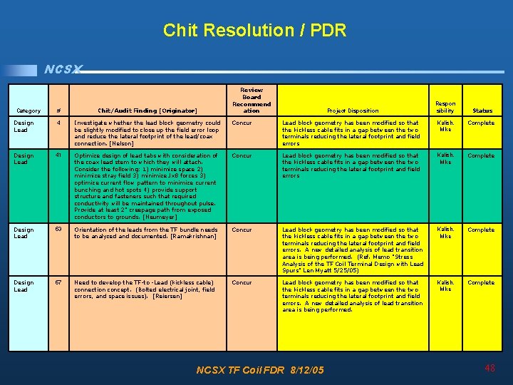
Chit Resolution / PDR NCSX Review Board Recommend ation Respon sibility # Chit/Audit Finding [Originator] Design Lead 4 Investigate whether the lead block geometry could be slightly modified to close up the field error loop and reduce the lateral footprint of the lead/coax connection. [Nelson] Concur Lead block geometry has been modified so that the kickless cable fits in a gap between the two terminals reducing the lateral footprint and field errors Kalish, Mike Complete Design Lead 41 Optimize design of lead tabs with consideration of the coax lead stem to which they will attach. Consider the following: 1) minimize space 2) minimize stray field 3) minimize Jx 8 forces 3) optimize current flow pattern to minimize current bunching and hot spots 4) provide support structure and fasteners such that required conductivity will be maintained throughout pulse. Provide at least 2" creepage path from exposed conductors to grounds. [Neumeyer] Concur Lead block geometry has been modified so that the kickless cable fits in a gap between the two terminals reducing the lateral footprint and field errors Kalish, Mike Complete Design Lead 53 Orientation of the leads from the TF bundle needs to be analyzed and documented. [Ramakrishnan] Concur Lead block geometry has been modified so that the kickless cable fits in a gap between the two terminals reducing the lateral footprint and field errors. A new detailed analysis of lead transition area is being performed. (Ref. Memo "Stress Analysis of the TF Coil Terminal Design with Lead Spurs" Len Myatt 5/25/05) Kalish, Mike Complete Design Lead 57 Need to develop the TF-to -Lead (kickless cable) connection concept. (Bolted electrical joint, field errors, and space issues). [Reiersen] Concur Lead block geometry has been modified so that the kickless cable fits in a gap between the two terminals reducing the lateral footprint and field errors. A new detailed analysis of lead transition area is being performed. Kalish, Mike Complete Category Project Disposition NCSX TF Coil FDR 8/12/05 Status 48
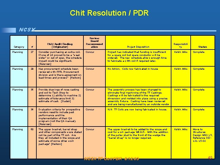
Chit Resolution / PDR NCSX Category # Chit/Audit Finding [Originator] Review Board Recommend ation Project Disposition Responsibili ty Status Planning 27 Consider purchasing an extra coil. If one of 18 proved to be a "weak sister" or out of spec, the schedule impact could be significant. [Reiersen] Concur Project has indicated that funding is insufficient for a spare coil but spare conductor will be ordered. The new schedule allows enough time to fabricate a 19 th coil if required later. Kalish, Mike Complete Planning 28 Has procurement schedule been reviewed with PPPL Procurement division and is there agreement on lead times and process? [Neilson] Concur No Action, Coils now fabricated in house Kalish, Mike Complete Planning 35 Provide drawings of nose casting and coil to Tech Shop to determine 1) ability to machine 2) estimate of tolerance limit 3) estimate of cast. [Dudek] Concur The assembly process has been changed to eliminate final machining of the TF Castings will be fabricated to the required dimension and molded into place using a precise assembly fixture. Casting have been reviewed and are being manufactured by an outside vendor Kalish, Mike Complete Planning 36 Evaluation criteria for prospective vendors need to include past performance and the implementation of their QA program (not the QA manual). [Reiersen] Concur N/A TF Coils are now being fabricated in house. Kalish, Mike Complete Planning 50 The upper bracket, barrel strap and other components were stated not be part of the TF coil. Are they all included in the scope and estimate of some other work package? [Neilson] Concur The upper bracket to be added to the scope and cost for work package WBS 15. With the addition of the puller stud to the front of the wedge the "barrel strap" is no longer required. Kalish, Mike Move to Structures Design WBS 15, Reference ICD 131 -15 -02 NCSX TF Coil FDR 8/12/05 49
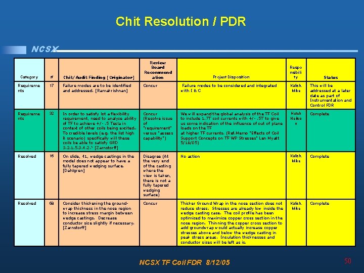
Chit Resolution / PDR NCSX Review Board Recommend ation Respo nsibili ty Category # Chit/Audit Finding [Originator] Requireme nts 17 Failure modes are to be identified and addressed. [Ramakrishnan] Concur Failure modes to be considered and integrated with I & C Kalish, Mike This will be addressed at a later date as part of Instrumentation and Control FDR Requireme nts 32 In order to satisfy lot a flexibility requirement, need to analyze ability of TF to achieve +/-. 5 Tesla in context of other coils being excited. . To credible levels (e. g. the list high B scenario) specifically will these coils be able to satisfy GRD 3. 2. 1. 5. 3. 4. 2. ? [Zarnstorff] Concur (Resolve issue of "requirement" versus "assess capability") We will expand the global analysis of the TF Coil to include 1. 7 T coil currents with +/-. 5 T to give us some indication of the influence of out of plane loads on the TF at higher TF currents. (Ref. Memo "Effects of Coil Support Concepts on TF WP Stresses" Len Myatt 5/16/05) Hutch Neilso n Complete Resolved 16 On slide, 41, wedge castings in the model does not appear to have a fully tapered wedging surface. [Dahlgren] Disagree (At the very end of the casting where the view is taken, there is not a fully tapered wedging surface) No action Kalish, Mike Complete Resolved 58 Consider thickening the groundwrap thickness in the nose region to increase stress margin between wedge castings. Decrease conductor size slightly if necessary. [Zarnstorff] Concur Thicker Ground Wrap in the nose section does not reduce stress. Stresses are already low inside the wedge casting case. The coil profile has been optimized to maximize copper cross section in the nose region. Thinning the copper cross section to add groundwrap would actually increase copper stresses above and below the wedge casting in peak stress areas. Insulation thicknesses and conductor sizes will be left as is. Kalish, Mike Complete Project Disposition NCSX TF Coil FDR 8/12/05 Status 50
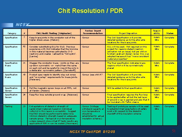
Chit Resolution / PDR NCSX Category # Chit/Audit Finding [Originator] Review Board Recommendation Project Disposition Respon sibility Status Specification 7 Keep braze joints in the conductor out of the higher stress areas. [Nelson] Concur The Coil Specification will provide detailed guidance as to the allowable locations for the braze joints Kalish, Mike Complete Specification 52 Consider substituting G 11 for G 10. Previous experience with G 10 indicates that the bromine in this material becomes activated by D-D neutrons and creates radioactive "hot spots". [Levine] Concur G 11 will be used. Not required on this project for reasons stated (neutron activation not an issue) but per chit on twisted racetrack design review G 11 was adopted because it has "more consistent material properties" Kalish, Mike Complete Specification Braze 31 Stagger the conductor braze - joints so they are up-down symmetric -or- make them the same on each coil and be careful to mount the coils in a stellarator -symmetric pattern. [Zarnstorff] Concur The final specification indicates braze regions which will be symmetrically placed Kalish, Mike Complete Specification Braze 43 Product spec needs to identify stay out zones and "no overlap" requirements for braze joints. [Reiersen] Concur (see chit #7 The Coil Specification will provide detailed guidance as to the allowable locations for the braze joints Kalish, Mike Complete Specification Sensor 9 Put the magnetic sensor loops on at PPPL, not at Vendor. [Nelson] Concur Will be added to final specification Kalish, Mike Complete Specification Sensor 26 Keep flux loop outside ground wrap. [Reiersen] Concur Final specification requires the flux loop to be applied after all but the last layer of ground wrap is applied and also that it be insulated with Teflon sleeve Kalish, Mike Complete Testing 23 Extrapolations of dielectric strength of sandwiched materials based on individual volts/mil in thin layers is unrealistic. Suggest the R&D should be performed to determine intrinsic dielectric strength based on adequate sample group. Perhaps at cryo temperature unless research shows that RT tests results are applicable of 80 K or can be scaled. [Neumeyer] Concur (Voltage withstand capacity at cryo temperature should be established for actual insulation scheme. ) Testing of prototype sample will be used to establish that large factors of safety exist with respect to the dielectric standoff of the insulation scheme Kalish, Mike Complete NCSX TF Coil FDR 8/12/05 51
Chit Resolution / PDR Category # NCSX Chit/Audit Finding [Originator] Review Board Recomm endation Project Disposition Respon sibility Status System Requirement 22 Instrumentation and control issues need to be addressed at FDR. It is a requirement that the TF System is responsible for generating. [Reiersen] Concur Kalish, Mike Will be addressed in separate I&C FDR System Requirement 21 Provide calculations values of resistance and inductance of the coil and establish the voltage to be impressed on the TF coil connection. [Ramakrishnan] Concur Analysis report will document the circuit parameters and power supply requirements Reierse n In Process System Requirement 25 Basis for current and voltage ratings not presented. Not clear whether scenarios/coils/power supply are coordinated. Inductance and resistance calculations not presented. Conductor heating calculation not presented. Is there a chance for higher than normal voltage on TF due to induction from modular, e. g. , If TF is open circuited during test shot on modular-only? [Neumeyer] Concur Needs formal document ation and checking. Analysis report will document the circuit parameters and power supply requirements Reierse n In Process System Requirement 45 The design shows that the TF Coil current is to be limited based on other coil currents. This dictates the use of a coil protection calculator, if the machine is to be properly protected. [Ramakrishnan] Concur The reference scenarios define the performance requirements for the TF coils. However, any waveform that will be run during operation will have to be vetted as being acceptable. This can be done by prior analysis of the input waveform or by a coil protection calculator. OUT OF SCOPE Kalish, Reierse n Complete System Requirement 54 Document the criteria used for selecting the number of turns and coils current [Ramakrishnan] Concur Analysis report will document the circuit parameters and power supply requirements Reierse n In Process System Requirement 55 A. What are the limits of the following? What Concur I^2 T limits can be set at 645 KA^2 secs which is a should be the protection factor of 1. 5 above the. 5 Tesla dissipated power and 1) over current still only results in an approximate temperature rise 2) I^2 T of less than 6 C. If it is assumed all of the modular B. Are there any stress limits that have to be coil power is dumped into the TF coil the d. T may get detected or corrected? as high as 14 C. The limit on the maximum allowable C. What is the factor of safety in the design for the temperature (and therefore on the I 2 t) will likely be above? [Ramakrishnan] set by the LN 2 system requiring some temperature headroom on maintaining single phase flow which is a function of the pressure in the system Current limits need to be set based on consideration of the Kalish, Reierse n In Process NCSX TF Coil FDR 8/12/05 currents in other coils 52
Analysis and Test NCSX • Requirements • Design • Review Issues / Chits • Analysis and Test – – PDR Analysis Review Winding Pack Prototype Testing Post PDR upgrade analysis Dowel Shear Testing • Fabrication • Summary NCSX TF Coil FDR 8/12/05 53
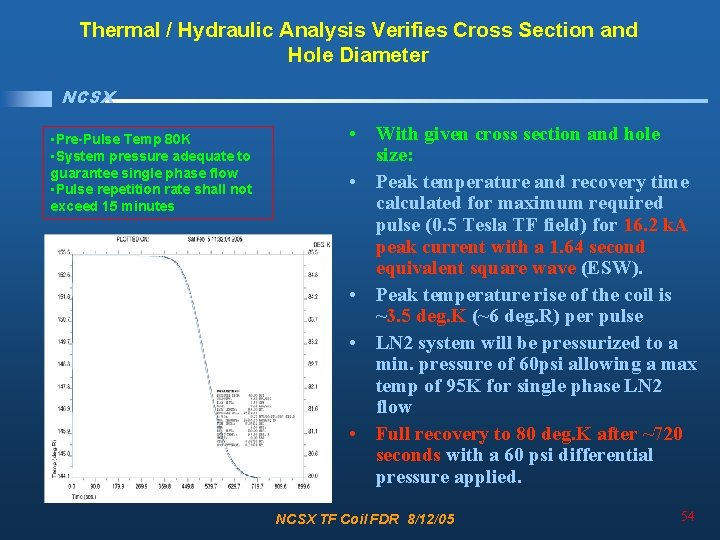
Thermal / Hydraulic Analysis Verifies Cross Section and Hole Diameter NCSX • Pre-Pulse Temp 80 K • System pressure adequate to guarantee single phase flow • Pulse repetition rate shall not exceed 15 minutes • With given cross section and hole size: • Peak temperature and recovery time calculated for maximum required pulse (0. 5 Tesla TF field) for 16. 2 k. A peak current with a 1. 64 second equivalent square wave (ESW). • Peak temperature rise of the coil is ~3. 5 deg. K (~6 deg. R) per pulse • LN 2 system will be pressurized to a min. pressure of 60 psi allowing a max temp of 95 K for single phase LN 2 flow • Full recovery to 80 deg. K after ~720 seconds with a 60 psi differential pressure applied. NCSX TF Coil FDR 8/12/05 54
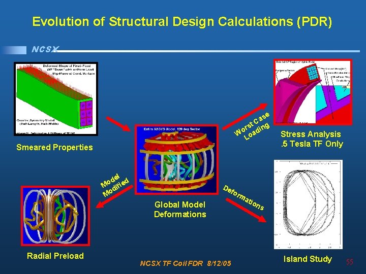
Evolution of Structural Design Calculations (PDR) NCSX e as C t rs ding o W oa L Smeared Properties l de ed o M ifi d Mo De fo Global Model Deformations Radial Preload Stress Analysis. 5 Tesla TF Only NCSX TF Coil FDR 8/12/05 rm ati on s Island Study 55
NCSX Structural Design Calculations, Results & Requirements • Work presented in a series of project memos: – “Material Property Data Base to be used for NCSX Analyses, ” 06/30/04. – “Calculating Smeared Properties of the TF Winding Pack for Use in Global Models, ” 01/03/05. – “Deformations in the NCSX TF Coil from all Field Sources and a Simplistic Linear Model, ” 01/03/05 – “Radial Preload Requirements for TF Coil Structural Continuity, 3 x 4 TF Array + Wedges, ” 01/13/05. – “Stress Analysis of the 3 x 4 Slip-Plane TF Coil with Cast SS Wedges, ” 01/12/05. • Following pages show the highlights of these analyses. NCSX TF Coil FDR 8/12/05 56
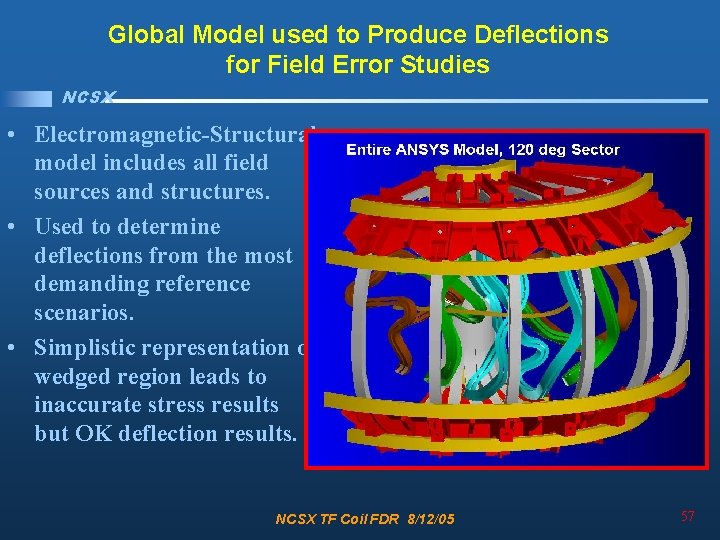
Global Model used to Produce Deflections for Field Error Studies NCSX • Electromagnetic-Structural model includes all field sources and structures. • Used to determine deflections from the most demanding reference scenarios. • Simplistic representation of wedged region leads to inaccurate stress results but OK deflection results. NCSX TF Coil FDR 8/12/05 57
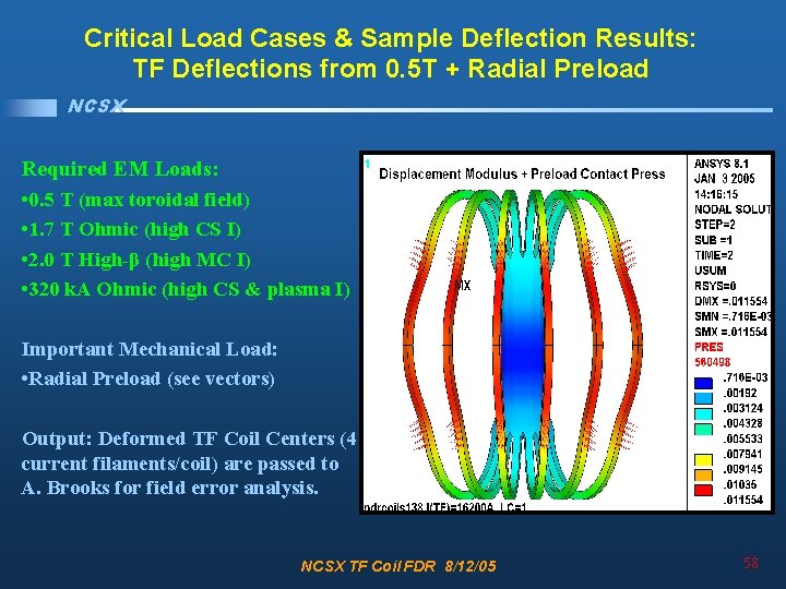
Critical Load Cases & Sample Deflection Results: TF Deflections from 0. 5 T + Radial Preload NCSX Required EM Loads: • 0. 5 T (max toroidal field) • 1. 7 T Ohmic (high CS I) • 2. 0 T High-β (high MC I) • 320 k. A Ohmic (high CS & plasma I) Important Mechanical Load: • Radial Preload (see vectors) Output: Deformed TF Coil Centers (4 current filaments/coil) are passed to A. Brooks for field error analysis. NCSX TF Coil FDR 8/12/05 58
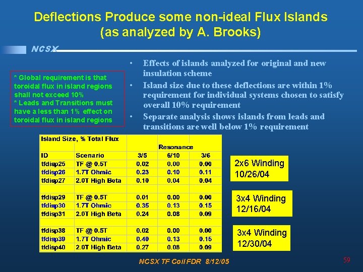
Deflections Produce some non-ideal Flux Islands (as analyzed by A. Brooks) NCSX • * Global requirement is that toroidal flux in island regions shall not exceed 10% * Leads and Transitions must have a less than 1% effect on toroidal flux in island regions • • Effects of islands analyzed for original and new insulation scheme Island size due to these deflections are within 1% requirement for individual systems chosen to satisfy overall 10% requirement Separate analysis shows islands from leads and transitions are well below 1% requirement 2 x 6 Winding 10/26/04 3 x 4 Winding 12/16/04 3 x 4 Winding 12/30/04 NCSX TF Coil FDR 8/12/05 59
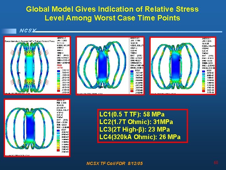
Global Model Gives Indication of Relative Stress Level Among Worst Case Time Points NCSX LC 1(0. 5 T TF): 58 MPa LC 2(1. 7 T Ohmic): 31 MPa LC 3(2 T High-β): 23 MPa LC 4(320 k. A Ohmic): 26 MPa NCSX TF Coil FDR 8/12/05 60
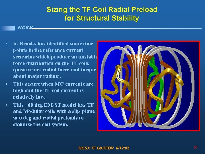
Sizing the TF Coil Radial Preload for Structural Stability NCSX • • • A. Brooks has identified some time points in the reference current scenarios which produce an unstable force distribution on the TF coils (positive net radial force and torque about major radius). This occurs when MC currents are high and the TF coil current is relatively low. This ± 60 deg EM-ST model has TF and Modular coils with a slip-plane at 0 deg and radial preloads to stabilize the coil system. NCSX TF Coil FDR 8/12/05 61
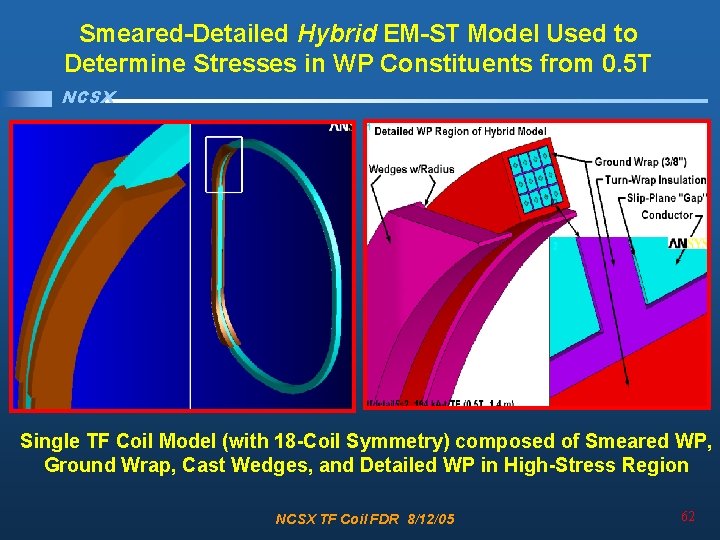
Smeared-Detailed Hybrid EM-ST Model Used to Determine Stresses in WP Constituents from 0. 5 T NCSX Single TF Coil Model (with 18 -Coil Symmetry) composed of Smeared WP, Ground Wrap, Cast Wedges, and Detailed WP in High-Stress Region NCSX TF Coil FDR 8/12/05 62
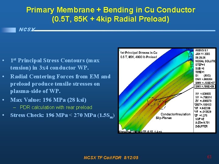
Primary Membrane + Bending in Cu Conductor (0. 5 T, 85 K + 4 kip Radial Preload) NCSX • 1 st Principal Stress Contours (max tension) in 3 x 4 conductor WP. • Radial Centering Forces from EM and preload produce tensile stresses on plasma-side of WP. • Max Value: 196 MPa (28 ksi) – PDR calculation with rear preload • Stress Check: 196 MPa < 270 MPa (1. 5 Sm) NCSX TF Coil FDR 8/12/05 63
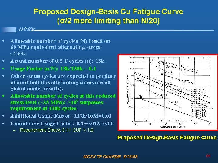
Proposed Design-Basis Cu Fatigue Curve (σ/2 more limiting than N/20) NCSX • • Allowable number of cycles (N) based on 69 MPa equivalent alternating stress: ~130 k Actual number of 0. 5 T cycles (n): 13 k Usage Factor (n/N): 13 k/130 k = 0. 1 Other stress cycles are expected to produce at most half this alternating stress (recall global model results). Allowable number of cycles at this reduced stress level (~35 MPa): >107 surpasses requirement of 130 k cycles Additional Usage Factor: 117 k/10 M=0. 01 Cumulative Usage Factor: 0. 1+0. 012=0. 11 – Requirement Check: 0. 11 CUF < 1. 0 Proposed Design-Basis Fatigue Curve NCSX TF Coil FDR 8/12/05 64
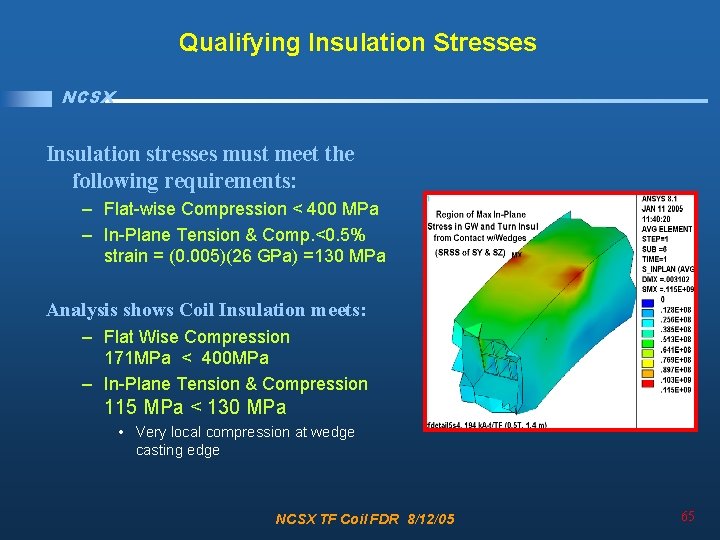
Qualifying Insulation Stresses NCSX Insulation stresses must meet the following requirements: – Flat-wise Compression < 400 MPa – In-Plane Tension & Comp. <0. 5% strain = (0. 005)(26 GPa) =130 MPa Analysis shows Coil Insulation meets: – Flat Wise Compression 171 MPa < 400 MPa – In-Plane Tension & Compression 115 MPa < 130 MPa • Very local compression at wedge casting edge NCSX TF Coil FDR 8/12/05 65
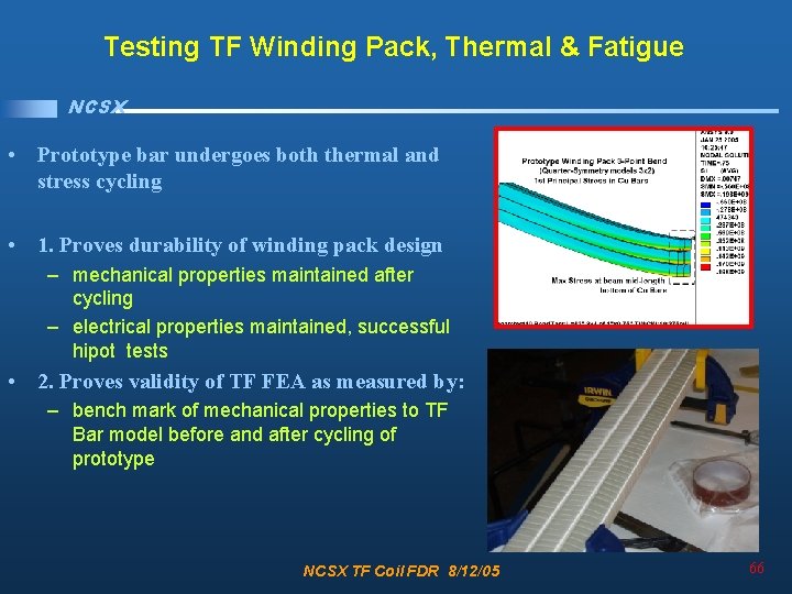
Testing TF Winding Pack, Thermal & Fatigue NCSX • Prototype bar undergoes both thermal and stress cycling • 1. Proves durability of winding pack design – mechanical properties maintained after cycling – electrical properties maintained, successful hipot tests • 2. Proves validity of TF FEA as measured by: – bench mark of mechanical properties to TF Bar model before and after cycling of prototype NCSX TF Coil FDR 8/12/05 66
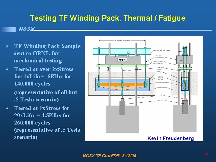
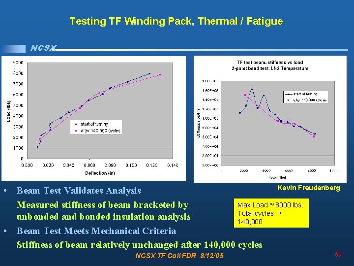
Testing TF Winding Pack, Thermal / Fatigue NCSX • TF Winding Pack Sample sent to ORNL for mechanical testing • Tested at over 2 x. Stress for 1 x. Life = 8 Klbs for 140, 000 cycles (representative of all but . 5 Tesla scenario) • Tested at 1 x. Stress for 20 x. Life = 4. 5 Klbs for 260, 000 cycles (representative of. 5 Tesla scenario) Kevin Freudenberg. NCSX TF Coil FDR 8/12/05 67
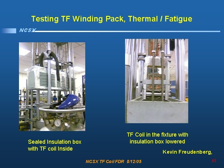
Testing TF Winding Pack, Thermal / Fatigue NCSX Sealed Insulation box with TF coil Inside TF Coil in the fixture with insulation box lowered Kevin Freudenberg, . NCSX TF Coil FDR 8/12/05 68
Testing TF Winding Pack, Thermal / Fatigue NCSX Kevin Freudenberg. • Beam Test Validates Analysis Max Load ≈ 8000 lbs. Measured stiffness of beam bracketed by Total cycles ≈ unbonded and bonded insulation analysis 140, 000 • Beam Test Meets Mechanical Criteria Stiffness of beam relatively unchanged after 140, 000 cycles NCSX TF Coil FDR 8/12/05 69
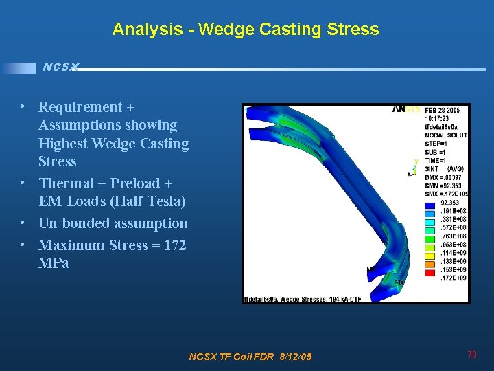
Analysis - Wedge Casting Stress NCSX • Requirement + Assumptions showing Highest Wedge Casting Stress • Thermal + Preload + EM Loads (Half Tesla) • Un-bonded assumption • Maximum Stress = 172 MPa NCSX TF Coil FDR 8/12/05 70
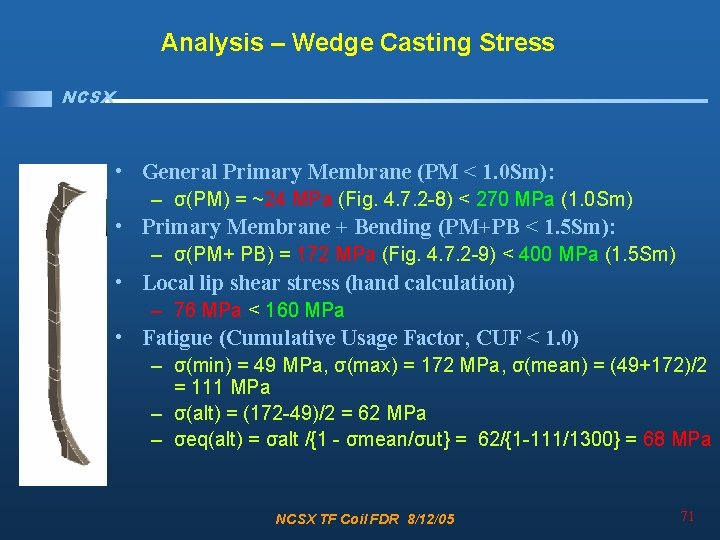
Analysis – Wedge Casting Stress NCSX • General Primary Membrane (PM < 1. 0 Sm): – σ(PM) = ~24 MPa (Fig. 4. 7. 2 -8) < 270 MPa (1. 0 Sm) • Primary Membrane + Bending (PM+PB < 1. 5 Sm): – σ(PM+ PB) = 172 MPa (Fig. 4. 7. 2 -9) < 400 MPa (1. 5 Sm) • Local lip shear stress (hand calculation) – 76 MPa < 160 MPa • Fatigue (Cumulative Usage Factor, CUF < 1. 0) – σ(min) = 49 MPa, σ(max) = 172 MPa, σ(mean) = (49+172)/2 = 111 MPa – σ(alt) = (172 -49)/2 = 62 MPa – σeq(alt) = σalt /{1 - σmean/σut} = 62/{1 -111/1300} = 68 MPa NCSX TF Coil FDR 8/12/05 71
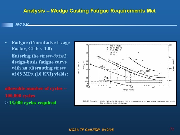
Analysis – Wedge Casting Fatigue Requirements Met NCSX • Fatigue (Cumulative Usage Factor, CUF < 1. 0) Entering the stress-data/2 design-basis fatigue curve with an alternating stress of 68 MPa (10 KSI) yields: allowable number of cycles ~ 100, 000 cycles > 13, 000 cycles required NCSX TF Coil FDR 8/12/05 72
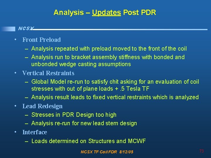
Analysis – Updates Post PDR NCSX • Front Preload – Analysis repeated with preload moved to the front of the coil – Analysis run to bracket assembly stiffness with bonded and unbonded wedge casting assumptions • Vertical Restraints – Global Model re-run to satisfy chit asking for an evaluation of coil stresses with out of plane loads +. 5 Tesla TF – Analysis result leads to fixed vertical restraints which is analyzed • Lead Redesign – Stresses in PDR Design too high – Analysis re-run for new lead stem design • Interface – Loads determined on Structures and MCWF NCSX TF Coil FDR 8/12/05 73
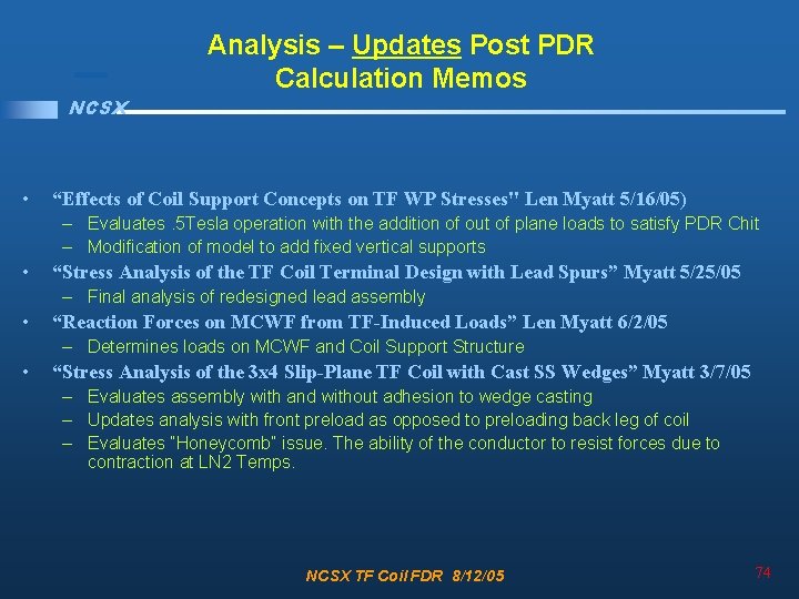
NCSX • Analysis – Updates Post PDR Calculation Memos “Effects of Coil Support Concepts on TF WP Stresses" Len Myatt 5/16/05) – Evaluates. 5 Tesla operation with the addition of out of plane loads to satisfy PDR Chit – Modification of model to add fixed vertical supports • “Stress Analysis of the TF Coil Terminal Design with Lead Spurs” Myatt 5/25/05 – Final analysis of redesigned lead assembly • “Reaction Forces on MCWF from TF-Induced Loads” Len Myatt 6/2/05 – Determines loads on MCWF and Coil Support Structure • “Stress Analysis of the 3 x 4 Slip-Plane TF Coil with Cast SS Wedges” Myatt 3/7/05 – Evaluates assembly with and without adhesion to wedge casting – Updates analysis with front preload as opposed to preloading back leg of coil – Evaluates “Honeycomb” issue. The ability of the conductor to resist forces due to contraction at LN 2 Temps. NCSX TF Coil FDR 8/12/05 74
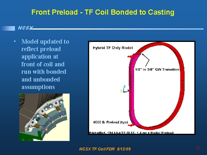
Front Preload - TF Coil Bonded to Casting NCSX • Model updated to reflect preload application at front of coil and run with bonded and unbonded assumptions NCSX TF Coil FDR 8/12/05 75
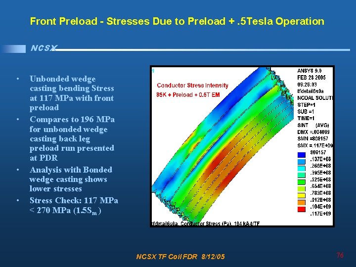
Front Preload - Stresses Due to Preload +. 5 Tesla Operation NCSX • • Unbonded wedge casting bending Stress at 117 MPa with front preload Compares to 196 MPa for unbonded wedge casting back leg preload run presented at PDR Analysis with Bonded wedge casting shows lower stresses Stress Check: 117 MPa < 270 MPa (1. 5 Sm ) NCSX TF Coil FDR 8/12/05 76
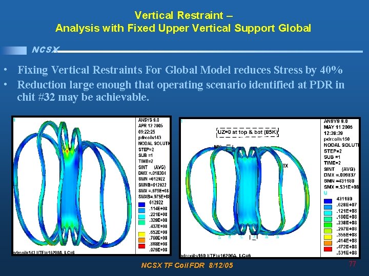
Vertical Restraint – Analysis with Fixed Upper Vertical Support Global NCSX • Fixing Vertical Restraints For Global Model reduces Stress by 40% • Reduction large enough that operating scenario identified at PDR in chit #32 may be achievable. NCSX TF Coil FDR 8/12/05 77
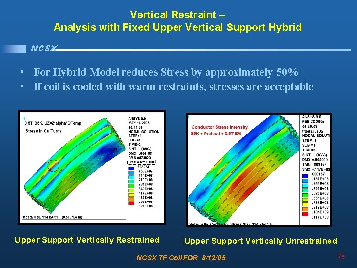
Vertical Restraint – Analysis with Fixed Upper Vertical Support Hybrid NCSX • For Hybrid Model reduces Stress by approximately 50% • If coil is cooled with warm restraints, stresses are acceptable Upper Support Vertically Restrained Upper Support Vertically Unrestrained NCSX TF Coil FDR 8/12/05 78
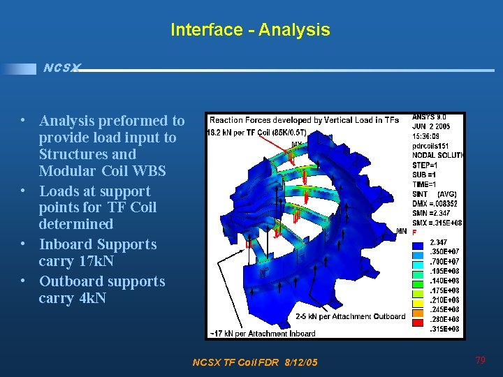
Interface - Analysis NCSX • Analysis preformed to provide load input to Structures and Modular Coil WBS • Loads at support points for TF Coil determined • Inboard Supports carry 17 k. N • Outboard supports carry 4 k. N NCSX TF Coil FDR 8/12/05 79
Lead Redesign – PDR Design = High Stresses NCSX • PDR Lead Design Produced stresses as high as 300 MPa • Lead Area was redesigned analyzed NCSX TF Coil FDR 8/12/05 80
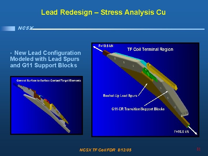
Lead Redesign – Stress Analysis Cu NCSX • New Lead Configuration Modeled with Lead Spurs and G 11 Support Blocks NCSX TF Coil FDR 8/12/05 81
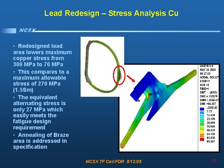
Lead Redesign – Stress Analysis Cu NCSX • Redesigned lead area lowers maximum copper stress from 300 MPa to 70 MPa • This compares to a maximum allowable stress of 270 MPa (1. 5 Sm) • The equivalent alternating stress is only 27 MPa which easily meets the fatigue design requirement • Annealing of Braze area is addressed in specification NCSX TF Coil FDR 8/12/05 82
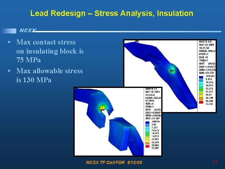
Lead Redesign – Stress Analysis, Insulation NCSX • Max contact stress on insulating block is 75 MPa • Max allowable stress is 130 MPa NCSX TF Coil FDR 8/12/05 83
Lead Redesign – Dowel Test NCSX • • The test assembly was placed on the 10, 000 lbf MTS machine with the load applied vertical through the assembly. The applied compressive load was ramped four times to successively higher levels: 1000 lbf, 4000 lbf, 6000 lbf and 8000 lbf. NCSX TF Coil FDR 8/12/05 Tom Kozub 84
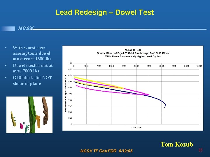
Lead Redesign – Dowel Test NCSX • • • With worst case assumptions dowel must react 1300 lbs Dowels tested out at over 7000 lbs G 10 block did NOT shear in plane Tom Kozub NCSX TF Coil FDR 8/12/05 85
Analysis Summary NCSX • Cu conductor satisfies monotonic and fatigue requirements • Insulation satisfies all relevant stress requirements • SS Wedge satisfies monotonic and fatigue requirements • Upgrades resulting from PDR chits have been analyzed and resulting stresses are now lower than in the original analysis • Testing supports analysis NCSX TF Coil FDR 8/12/05 86
Fabrication NCSX • • Requirements Design Review Issues / Chits Analysis and Test • Fabrication – – Facility / Method Specification Measurement and Test Procurements / Bill of Material • Summary NCSX TF Coil FDR 8/12/05 87
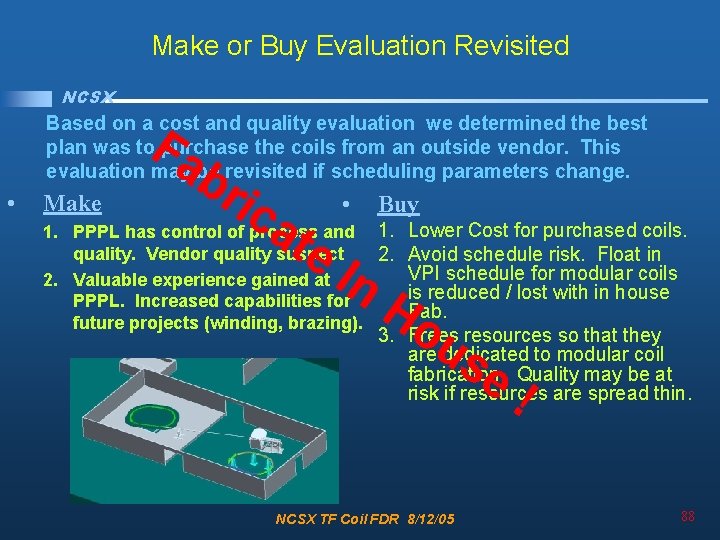
Make or Buy Evaluation Revisited NCSX Based on a cost and quality evaluation we determined the best plan was to purchase the coils from an outside vendor. This evaluation may be revisited if scheduling parameters change. Fa • Make br ica te • Buy 1. PPPL has control of process and 1. Lower Cost for purchased coils. quality. Vendor quality suspect 2. Avoid schedule risk. Float in VPI schedule for modular coils 2. Valuable experience gained at is reduced / lost with in house PPPL. Increased capabilities for Fab. future projects (winding, brazing). In H 3. o Frees resources so that they areu dedicated to modular coil se Quality may be at fabrication. risk if resources are spread thin. ! NCSX TF Coil FDR 8/12/05 88
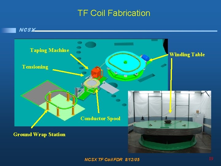
TF Coil Fabrication NCSX Taping Machine Winding Table Tensioning Conductor Spool Ground Wrap Station NCSX TF Coil FDR 8/12/05 89
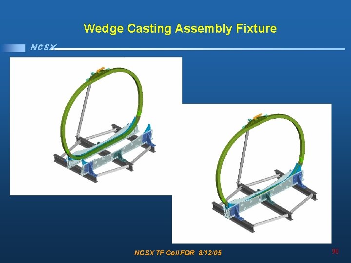
Wedge Casting Assembly Fixture NCSX TF Coil FDR 8/12/05 90
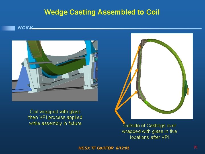
Wedge Casting Assembled to Coil NCSX Coil wrapped with glass then VPI process applied while assembly in fixture Outside of Castings over wrapped with glass in five locations after VPI NCSX TF Coil FDR 8/12/05 91
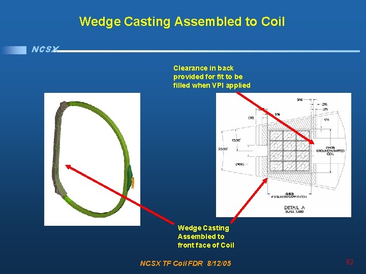
Wedge Casting Assembled to Coil NCSX Clearance in back provided for fit to be filled when VPI applied Wedge Casting Assembled to front face of Coil NCSX TF Coil FDR 8/12/05 92
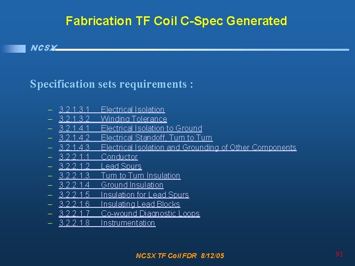
Fabrication TF Coil C-Spec Generated NCSX Specification sets requirements : – – – – 3. 2. 1. 3. 1 3. 2. 1. 4. 2 3. 2. 1. 4. 3 3. 2. 2. 1. 1 3. 2. 2. 1. 2 3. 2. 2. 1. 3 3. 2. 2. 1. 4 3. 2. 2. 1. 5 3. 2. 2. 1. 6 3. 2. 2. 1. 7 3. 2. 2. 1. 8 Electrical Isolation Winding Tolerance Electrical Isolation to Ground Electrical Standoff, Turn to Turn Electrical Isolation and Grounding of Other Components Conductor Lead Spurs Turn to Turn Insulation Ground Insulation for Lead Spurs Insulating Lead Blocks Co-wound Diagnostic Loops Instrumentation NCSX TF Coil FDR 8/12/05 93
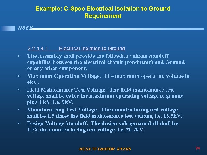
Example: C-Spec Electrical Isolation to Ground Requirement NCSX 3. 2. 1. 4. 1 • • • Electrical Isolation to Ground The Assembly shall provide the following voltage standoff capability between the electrical circuit (conductor) and Ground or any other component. Maximum Operating Voltage. The maximum operating voltage is 4 k. V. Field Maintenance Test Voltage. The field maintenance test voltage shall be twice the maximum operating voltage to ground plus 1 k. V, i. e. 9 k. V. Manufacturing Test Voltage. The manufacturing test voltage shall be 1. 5 times the field maintenance test voltage, i. e. 13. 5 k. V. Design Voltage Standoff. The design voltage standoff shall be 1. 5 X the manufacturing test voltage, i. e. 20. 2 k. V. NCSX TF Coil FDR 8/12/05 94
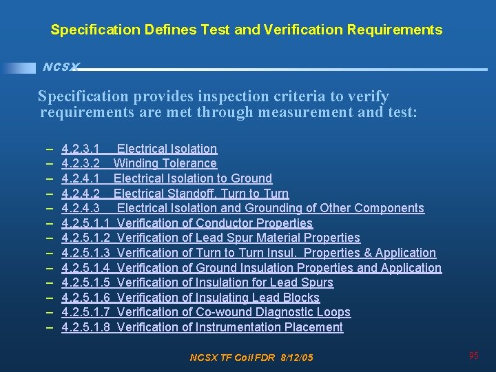
Specification Defines Test and Verification Requirements NCSX Specification provides inspection criteria to verify requirements are met through measurement and test: – – – – 4. 2. 3. 1 Electrical Isolation 4. 2. 3. 2 Winding Tolerance 4. 2. 4. 1 Electrical Isolation to Ground 4. 2 Electrical Standoff, Turn to Turn 4. 2. 4. 3 Electrical Isolation and Grounding of Other Components 4. 2. 5. 1. 1 Verification of Conductor Properties 4. 2. 5. 1. 2 Verification of Lead Spur Material Properties 4. 2. 5. 1. 3 Verification of Turn to Turn Insul. Properties & Application 4. 2. 5. 1. 4 Verification of Ground Insulation Properties and Application 4. 2. 5. 1. 5 Verification of Insulation for Lead Spurs 4. 2. 5. 1. 6 Verification of Insulating Lead Blocks 4. 2. 5. 1. 7 Verification of Co-wound Diagnostic Loops 4. 2. 5. 1. 8 Verification of Instrumentation Placement NCSX TF Coil FDR 8/12/05 95
Example: C-Spec Electrical Isolation to Ground Component Definition & Verification NCSX • • 3. 2. 2. 1. 4 Ground Insulation The ground insulation is composed of. 015 inch thick by two inch wide S 2 glass. The S 2 glass is applied in half lap layers to bring the total build of the turn to turn insulation to. 125 inches at the front leg of the coil and . 375 inches around the top, bottom, and back leg of the coil (ref. dwg. SE 131 -003). The glass and tape thicknesses, width and number of layers may be adjusted to reach the required overall thickness and to facilitate manufacturing requirements with the approval of the WBS manager. Any changes in the groundwrap insulation build up must meet the TF electrical standoff requirements. The number of ground wrap layers is to be optimized so that the compression of the coil in the VPI mold minimizes resin rich areas. Voids in the corners of the VPI mold are to be eliminated with the use of radiused fillers. Measurements and parameters such as the number of layers are to be recorded in the winding procedure for each coil Ref Section 3. 2. 1. 4. 1. 4. 2. 4. 1 Verification Electrical Isolation to Ground The completed coil will be tested at 13. 5 k. V. to ground and to the wedge castings Ref. Section 3. 2. 1. 4. 1 NCSX TF Coil FDR 8/12/05 96
Fabrication / Measurement NCSX • To maintain required tolerances measurements will be closely monitored and recorded during coil winding – – – Mandrel will be measured and place precisely Coil Geometry when removed from mandrel for ground wrap Ground insulation thickness Post VPI coil Geometry Positioning of Coil for wedge casting installation • Tracking of measurements will ensure consistency from coil to coil • All measurements will be documented in fabrication procedure NCSX TF Coil FDR 8/12/05 97
Fabrication / Test NCSX • The plan for the electrical testing of the TF coils is to test: – – – Resistance Inductance Megger Hipot Impulse (used to identify breakdown in the turn to turn resistance) • We will perform each of these tests at room temperature before and after cryogenic cycling for the first coil • At room temperature for subsequent coils NCSX TF Coil FDR 8/12/05 98
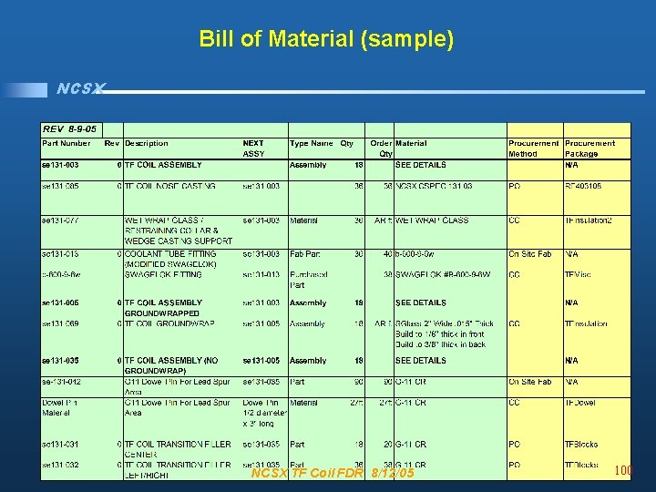
Procurements to Support Fabrication NCSX • Specifications and SOWs have been approved and orders are ongoing for two major procurements – TF Coil Conductor (due at end of Sept. ) – Wedge Castings • Remaining procurements critical to fabrication schedule – TF Lead spur copper – G 11 Lead blocks • Bill of Material Generated to Track Procurements through the Fabrication Cycle NCSX TF Coil FDR 8/12/05 99
Bill of Material (sample) NCSX TF Coil FDR 8/12/05 100
Summary NCSX • • • Requirements Design Review Issues / Chits Analysis and Test Fabrication • Summary – Interfaces – Charge Addressed NCSX TF Coil FDR 8/12/05 101
Interfaces NCSX Scope Lead Responsibility Deliverable Determine differential pressure across the coil, minimum inlet pressure, and flow requirements for Cryogenic System WBS 62 Memo provided to WBS 17 in the form of an ICD defining requirements Provide Voltage standoff requirements vs design standoff of winding pack insulation scheme WBS 4 Table summarizing voltage standoff requirements to be documented in ICD Determine effects of EM loading from other coil systems WBS 132 WBS 14 Requirements provided to WBS 131 in GRD includes current profiles for all coils. Calculation memo documents overall effect of EM loads including PF and Modular coils Verify no physical interferences between Coils and MCWF WBS 14 Pro E Model verifies no interferences Verify no physical interferences between Coils and Vacuum Vessel Ports WBS 12 Pro E Model to be used to verifies no interferences NCSX TF Coil FDR 8/12/05 102
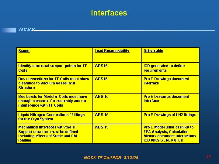
Interfaces NCSX Scope Lead Responsibility Deliverable Identify structural support points for TF Coils WBS 15 ICD generated to define requirements Bus connections for TF Coils must show clearance to Vacuum Vessel and Structure WBS 16 Pro E Drawings document interface Bus Leads for Modular Coils must have enough clearance for assembly and no interference with TF Coils WBS 16 Pro E Drawings document interface Liquid Nitrogen Connections / Fittings for the Cryo System WBS 16 Pro E Drawings of LN 2 fittings Mechanical interfaces with the TF Support structure must be defined including effects of Static and EM loading WBS 15 Pro E Model used as input to FEA Analysis, Calculation Memos document interactions ICD WAS GENERATED NCSX TF Coil FDR 8/12/05 103
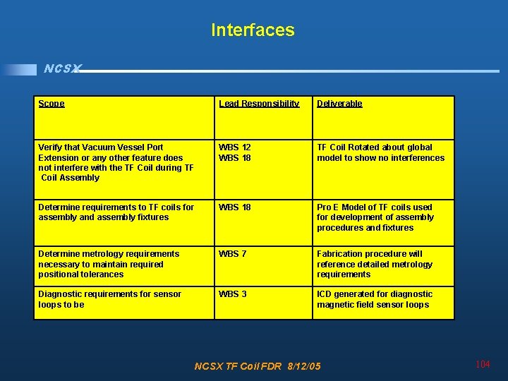
Interfaces NCSX Scope Lead Responsibility Deliverable Verify that Vacuum Vessel Port Extension or any other feature does not interfere with the TF Coil during TF Coil Assembly WBS 12 WBS 18 TF Coil Rotated about global model to show no interferences Determine requirements to TF coils for assembly and assembly fixtures WBS 18 Pro E Model of TF coils used for development of assembly procedures and fixtures Determine metrology requirements necessary to maintain required positional tolerances WBS 7 Fabrication procedure will reference detailed metrology requirements Diagnostic requirements for sensor loops to be WBS 3 ICD generated for diagnostic magnetic field sensor loops NCSX TF Coil FDR 8/12/05 104
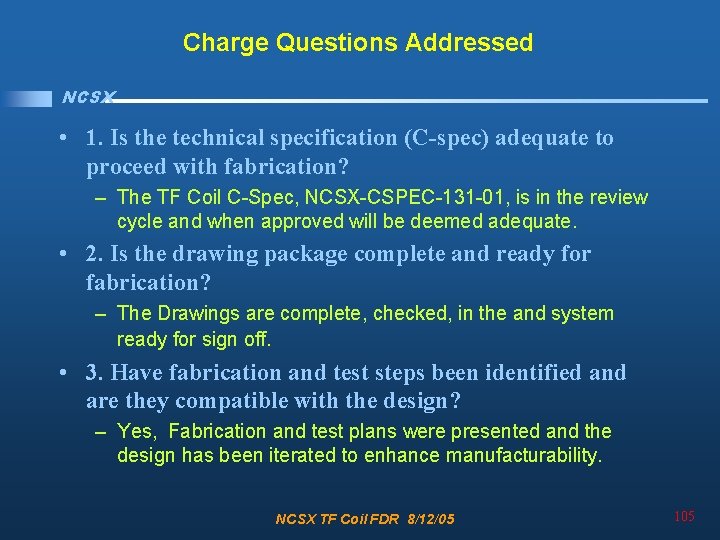
Charge Questions Addressed NCSX • 1. Is the technical specification (C-spec) adequate to proceed with fabrication? – The TF Coil C-Spec, NCSX-CSPEC-131 -01, is in the review cycle and when approved will be deemed adequate. • 2. Is the drawing package complete and ready for fabrication? – The Drawings are complete, checked, in the and system ready for sign off. • 3. Have fabrication and test steps been identified and are they compatible with the design? – Yes, Fabrication and test plans were presented and the design has been iterated to enhance manufacturability. NCSX TF Coil FDR 8/12/05 105
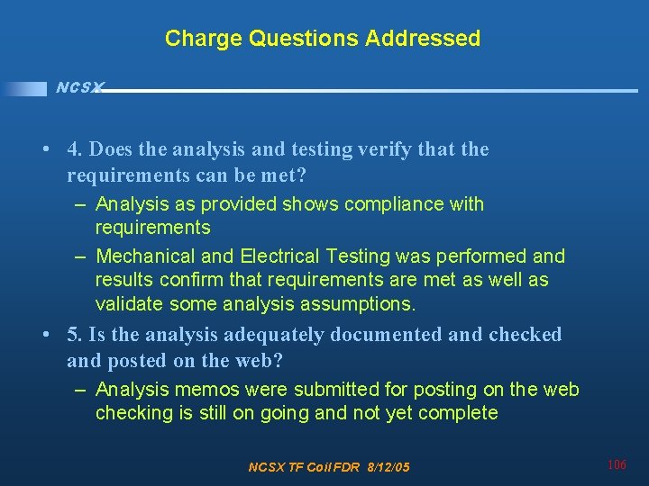
Charge Questions Addressed NCSX • 4. Does the analysis and testing verify that the requirements can be met? – Analysis as provided shows compliance with requirements – Mechanical and Electrical Testing was performed and results confirm that requirements are met as well as validate some analysis assumptions. • 5. Is the analysis adequately documented and checked and posted on the web? – Analysis memos were submitted for posting on the web checking is still on going and not yet complete NCSX TF Coil FDR 8/12/05 106
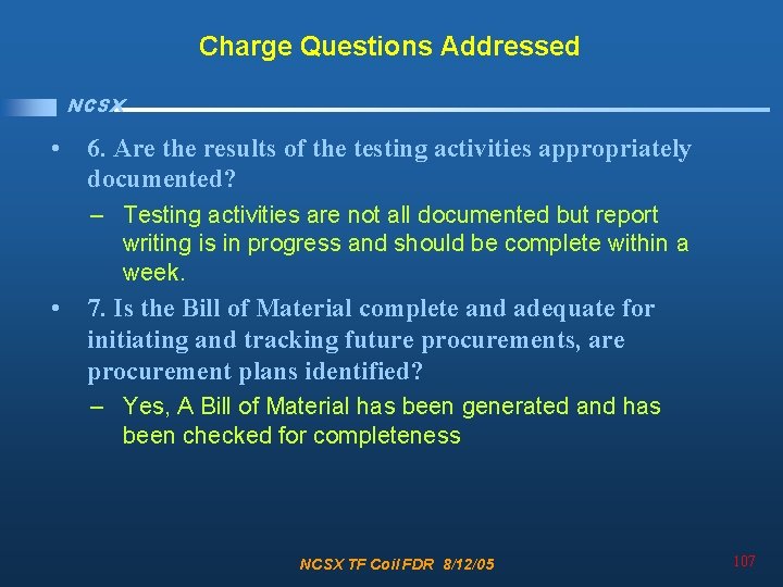
Charge Questions Addressed NCSX • 6. Are the results of the testing activities appropriately documented? – Testing activities are not all documented but report writing is in progress and should be complete within a week. • 7. Is the Bill of Material complete and adequate for initiating and tracking future procurements, are procurement plans identified? – Yes, A Bill of Material has been generated and has been checked for completeness NCSX TF Coil FDR 8/12/05 107
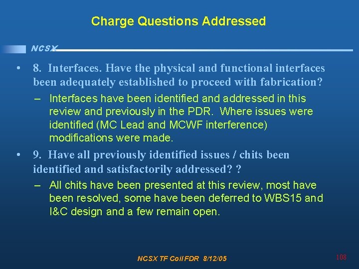
Charge Questions Addressed NCSX • 8. Interfaces. Have the physical and functional interfaces been adequately established to proceed with fabrication? – Interfaces have been identified and addressed in this review and previously in the PDR. Where issues were identified (MC Lead and MCWF interference) modifications were made. • 9. Have all previously identified issues / chits been identified and satisfactorily addressed? ? – All chits have been presented at this review, most have been resolved, some have been deferred to WBS 15 and I&C design and a few remain open. NCSX TF Coil FDR 8/12/05 108
Charge Questions Addressed NCSX • 10. Has any additional work or documentation that should be done for completion of the TF final design been identified? – – – Complete and Document Calculation Checking Post all checked calculations on web Final Signoff of Drawings Final Signoff of C-Spec Resolve System Engineering chits and create requirements for coil protection systems – Specify instrumentation (separate review) – Post Test Reports – Sign off and Post ICDs NCSX TF Coil FDR 8/12/05 109