NC CNC TECHNOLOGY CADCAMCAE Most machines have more


 Linear")


 Sequence Number (N-Words) (ii) Preparatory functions (G words) (iii) Miscellaneous functions (M-words) (iv)")


 THE PART PROGRAMMER’S JOB B) THE COMPUTER’S JOB")


 POINT-TO-POINT MOTIONS • They are")
 CONTOURING MOTIONS • There are six contouring motion commands. • GOLFT")


 System • Computer is linked directly to regular NC controller unit. •")


- Slides: 135
NC & CNC TECHNOLOGY CAD/CAM/CAE
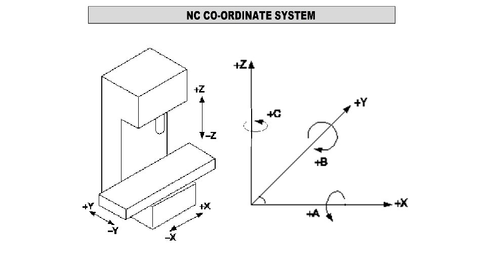
• Most machines have more than one slide ways • It is arranged perpendicular to one another • Each slide is fitted with a control system • In order to give commands to the control system the axes should be properly identified • Part programmer must be familiar with the axes on the CNC
• The axes on the NC is divided into two types: (i) Linear axes : X, Y and Z axes are identified as linear axes. (ii) Rotary axes : A, B and C axes are identified as rotary axes.
Z-axis : • Main spindle axis. • Positive Z-axis causes the cutting tool to move away from the work piece. (i. e. it increases the distance). X-axis : • It is always horizontal and parallel to the work piece surface. • It indicates the longitudinal travel of the work table. • Positive X is identified as being to the right. Y-axis : • It is perpendicular to both X and Z-axes. • It is also horizontal and indicates the cross travel of the table.
A-axis : • Axis of rotary motion of a tool along X-axis. • Clockwise rotation is considered as positive movement • Identified by looking in +X direction. B-axis : • It is the axis of rotary motion of a tool along Y-axis. • Clockwise rotation is considered as positive movement • Identified by looking in +Y direction. C-axis : • It is the axis of rotary motion of a tool along Z-axis. • Clockwise rotation is considered as positive movement • Identified by looking in +Z direction.
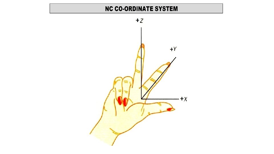
Thumb Rule for Axis Identification • Using right hand for axis identification is known as RHTR • Z-axis indicated by the middle finger of the right hand. • X-axis - thumb. • Y-axis -index finger of the right hand. • Positive direction of all the three axes is along the outward direction of the fingers (away from the palm). • Negative direction is along the fingers pointing towards the palm.
• Based on control system characteristics • Point to point position system. • Straight line system. • Contouring (continuous path) • Based on positioning coordinates : • Incremental system. • Absolute system. • Based on feedback or type of control system • Open loop system. • Closed loop system.
• Based on control system characteristics • Point to point position system. • Straight line system. • Contouring (continuous path)
POINT TO POINT SYSTEM : • Cutting tool moves from one point to another point. • No machining between two points. • Suitable for drilling, reaming, counter boring, tapping, spot welding. • Tool movement between location is very fast. • Path accomplished is not important in such system. • Each axis is driven separately.
STRAIGHT LINE SYSTEM • Tool feed is controlled in such systems. • Tool moves in straight line during machining operation. • Application: milling of slots, grooves, turning • Can also perform point to point movement. • Only Straight line cuts parallel to the axes can be programmed. • Angular cuts are not possible with such system. • Tool motion along both axes is controlled simultaneously.
CONTOURING SYSTEM Most complex, flexible and expensive system. Enables the machining of profiles, contours and curved surfaces. Tool and work piece motions are controlled along many axes, simultaneously. Tool feed rate is very closely controlled so as to move the tool simultaneously in required directions by synchronizing movement in both directions. Machining of curved profile is accomplished by breaking into short straight lines that approximate the curve.
Cutter path for Point to point, Straight line and Contour system
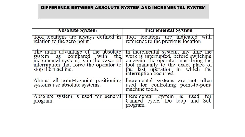
ABSOLUTE SYSTEM • Co-ordinates of points always taken from fixed point. • Generally the south west corner of the table for milling • W/p centre point on other end of chuck for lathe • It has an advantage to write the program easily • It is also easy to check and edit a program
INCREMENTAL SYSTEM • Coordinates of any points are calculated with reference to the previous position of the tool. • Difficult to edit program written in this mode. • Its special use is in writing subroutine programs.
Point P 1 P 2 P 3 P 4 Co-ordinates 1, 4 2, 1 7, 6 3, 2 Point P 1 P 2 P 3 P 4 Co-ordinates 1, 4 1, -3 5, 5 -4, -4
• Most important component in the CNC system is the part programming. • Slight error in program can change dimensions of final component. • Program uses various words like G-words, N-words etc. to write a CNC program. • These words are called as NC words.
(i) Sequence Number (N-Words) (ii) Preparatory functions (G words) (iii) Miscellaneous functions (M-words) (iv) Co-ordinates (X, Y and Z words) (v) Feed Function (F-word) (vi) Spindle Speed Function (S-word) (vii) Tool Selection Function (T-word)
• Prepares controller to execute instructions in part program. • Represented in two digits preceded by the letter G. • More than one G-code can be written in same block • G 90 G 21 G 94 but must be from different groups. • Two G-codes from same group execute last one • Example: N 90 G 01 X 35 Y 10 F 100 EOB • All G-codes are either modal or non-modal. • Modal codes stay in effect until they are cancelled by another code of the same group. • Example, G 90 is cancelled by G 91, G 21 is cancelled by G 20.
• The miscellaneous functions are used to specify certain miscellaneous functions like spindle start and stop, coolant on and off etc. • The miscellaneous function is represented in two digits preceded by the letter M. • Only one M-code can be programmed in a block. • All M-codes are modal.
• Various NC words are used to write one block of instruction • Each block of instruction is separated by EOB • Until the controller executes the current block, it does not jump to the next block of instruction. • In general the blocks of instruction looks as shown below: N 10 G 90 G 21 G 94 G 40 EOB N 20 M 03 S 1100 M 08 EOB • The set of various blocks of instructions which tells the machine tool about the steps to be performed to manufacture a component is known as part programming.
Fixed Block Format • Instructions are always given in same sequence • Every block to carry all instructions (even unchanged in preceding) • Only figures are provided in the program • Digits within each word must be of same length. N 0050 0060 G 00 00 X 20 90 Y 30 30 Z 00 00 F 150 S 1000 EOB
TAB Sequential Format Instructions are given in sequence similar to FBF But each word is separated by the TAB character. Advantage: Same digit need not be written again. But to maintain sequence of words, TAB should be written in the succeeding block. N 0050 TAB 0060 TAB G 00 TAB X Y 20 TAB 30 TAB 90 TAB Z F S 00 TAB 150 TAB 100 EOB TAB EOB
Word Address Format • Standardized format by EIA • Most widely used. • Each data is preceded by word called - NC word • Each alphabet represent particular co-ordinate or function. • Advantage: • Same words need not be written again. • Less time • Less memory • Easy editing N 0050 G 00 X 20 Y 30 Z 00 F 150 S 1000 N 0060 X 90 EOB
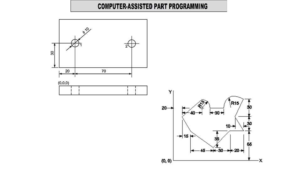
Position X and Y Co-ordinates No. 1 20, 30 2 100, 30 3 100, 70
Program 03216 N 05 G 28 U 00 V 00 W 00 EOB N 10 G 90 G 21 G 94 EOB N 15 M 03 S 1100 M 08 EOB N 20 G 00 Z 4 EOB Description Program number Return to machine reference position. Absolute mode, input in mm, feed in mm/min. Spindle starts clockwise direction, spindle speed, coolant on. Rapid travel of tool to 4 mm above the plate surface. N 25 G 00 X 20 Y 20 EOB N 30 G 01 Z-5 F 90 EOB Rapid travel of tool to position 1 (20, 30). Movement of tool 5 mm inside the work piece. (drilling) [Total tool movement is 9 mm in Z direction] N 35 G 00 Z 4 EOB Rapid travel of tool to 4 mm above the plate surface. N 40 G 00 X 10 Y 20 EOB N 45 G 01 Z-5 F 90 EOB Rapid travel of tool to position 2 (100, 30). Movement of tool 5 mm inside the workpiece. (drilling) N 50 G 00 Z 4 EOB Rapid travel of tool to 4 mm above the plate surface. N 55 G 00 Y 60 EOB N 60 G 01 Z-5 F 90 EOB Rapid travel of tool to position 3(100, 70). Movement of tool 5 mm inside the workpiece. (drilling). N 65 G 00 Z 5 EOB Rapid travel of tool to 5 mm above the plate surface. N 70 G 28 U 00 V 00 W 00 EOB N 75 M 05 EOB N 80 M 09 EOB N 85 M 30 EOB Rapid return to machine reference position. Spindle stop. Coolant off. Program end and tape rewind.
• Greater accuracy achieved. • Better machine utilization hence reduced idle time. • High production rate as speed, feed, depth of cut are optimum for best quality. • Lower tooling cost, per piece in mass production. • Jigs and fixtures cost can be reduced. • Reduced cycle time. By: Prashant Ambadekar
• Better tool life and machinability. • Less scrap due to consistent accuracy, less errors. • Design changes are possible. Any change in design is feasible at lowest cost. • Productivity can be improved to great extent. • Tool setup time can be reduced. By: Prashant Ambadekar
• Most suitable for continuous and better production. • Program can be stored and used again when required. • Optimum speed and feed for best surface finish can be used. • Excellent reliability as dimensions are based on programs. • Reduced in-process inventory. • Higher repeatability and improved product quality. By: Prashant Ambadekar • Less operator skill required to run CNC machine.
• CNC machines are more expensive • CNC machines are more complex machines • Cost of control systems used is high • Maintenance cost is high • The CNC machine operator needs basic training and skills, enough to supervise several machines. By: Prashant Ambadekar
• Most parts machined on NC systems are complex. • In complicated jobs manual part programming • Is extremely tedious task • subject to errors. • Computer assist in part programming process. • It perform calculations which the programmer would otherwise be forced to do. • saves time • results in a more accurate and efficient part program.
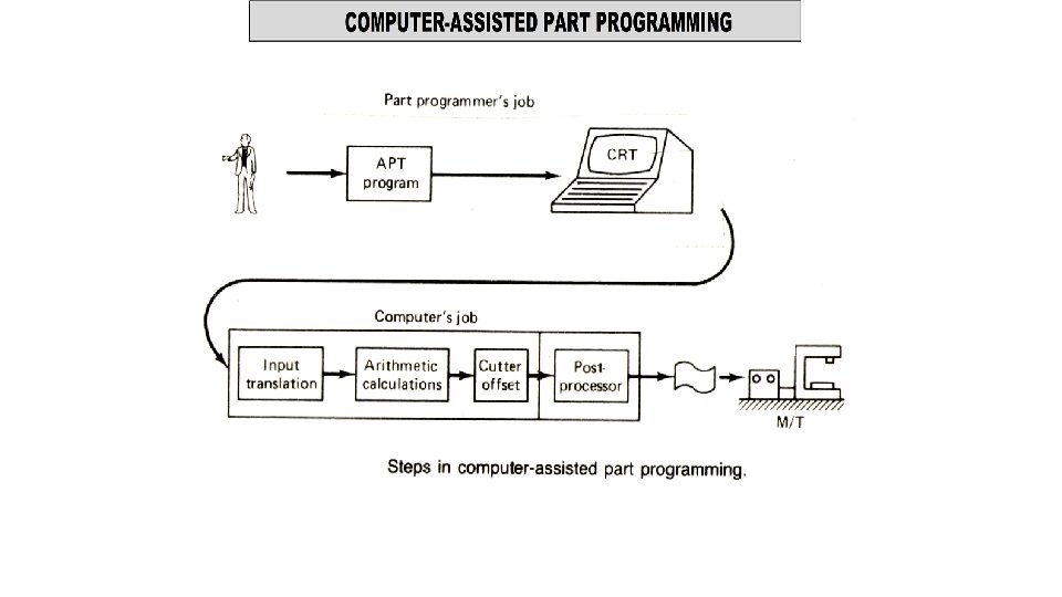
A) THE PART PROGRAMMER’S JOB B) THE COMPUTER’S JOB
• Process planning • Part programming • Tape preparation • Tape verification • Production
ROUTE SHEET Part name: _____ Material: ______ Part Drawing: Part no. : _____ Quantity: _____ Hardness: _____ Due Date: _____ Operation No. Operation Description Machine Dept. Tools Time (min) Required Set up time Operation time Total time
THE PART PROGRAMMER’S JOB • NC procedure is followed. • Programmers responsibility consists of two steps: 1. Defining the work piece geometry. Basic geometric elements. Enumerate the elements out of which the part is composed. Identify each geometric element and define its location. 2. Specifying the operation sequence and tool path. Construct the path to be followed by cutter. Step by step sequence. use previously defined geometric statements. Use motion commands to direct the tool.
THE COMPUTER’S JOB 1. Input translation 2. Arithmetic calculations 3. Cutter offset computation 4. Post processor
1. Input translation • Part programmer enters the program written in APT. • IT unit converts it in to computer usable form. 2. Arithmetic calculations • Solves the mathematics required to generate the surface. • Performs all the calculations. • Frees the programmer form geometric calculations.
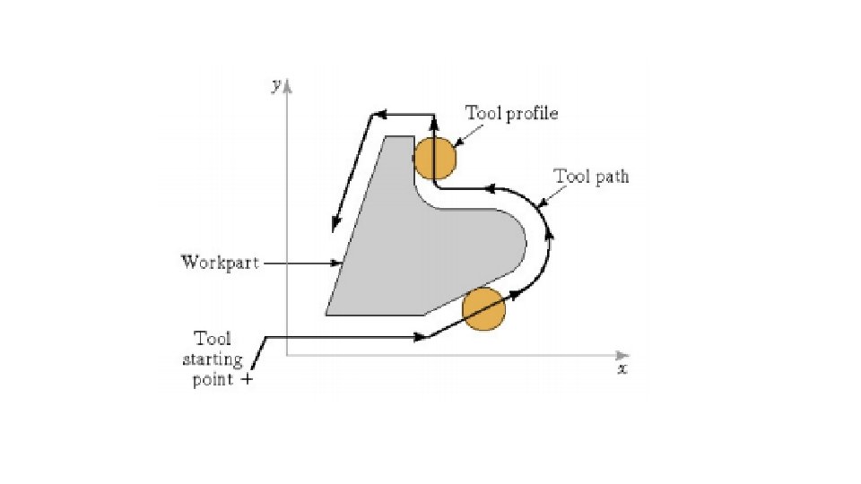
3. Cutter offset computation • Part programmer constructs the tool path. • Actual path is different. • Tool path is defined for center of cutter. • Machining takes place at periphery.
4. Post processor • It is a separate computer program. • It is written to prepare punched tape. • Input from above. • Output is correct NC tape.
• APT is not only an NC language. • It is also the computer program that performs the calculations to generate cutter positions based on APT statements. • APT is a 3 -D system that can be used to control upto 5 axes. • It can cover variety of machining operations. • There are over 400 words in APT vocabulary.
• There are four types of statements in APT language. • Geometric statement Defines the geometric elements that comprise the work piece. • Motion statement Defines the path followed by the tool. • Post processor statement Specifies speeds and feeds. • Auxiliary statement • Used to identify part, tolerance, tool etc.
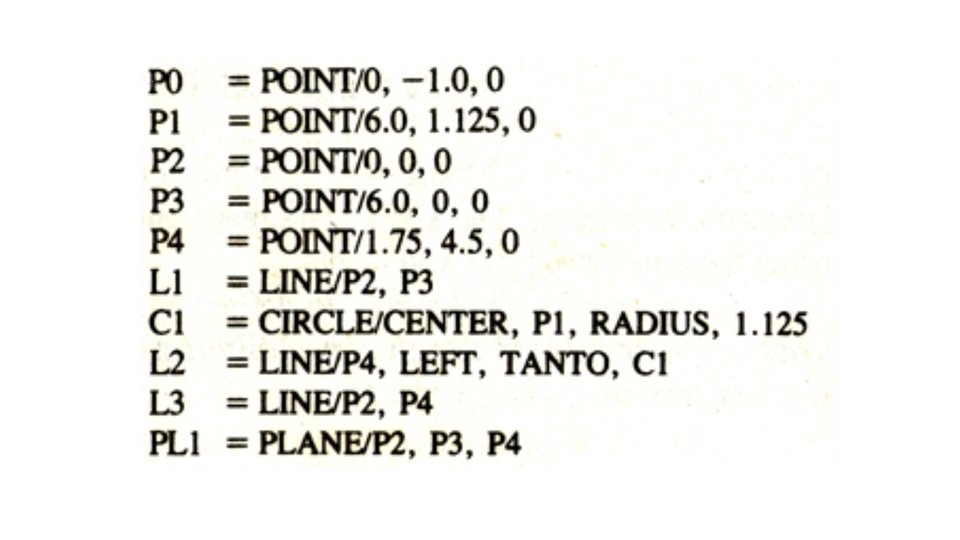
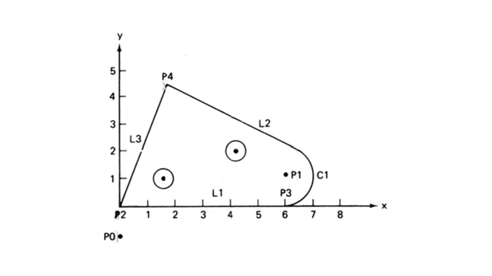
Geometric statement • Its general form is Symbol = geometry type / descriptive data e. g. P 1 = POINT / 3. 0, 5. 0, 0. 0 It has three sections. • Symbol Combination of alphabet or numbers (max 6) (atleast 1 alphabet) • APT vocabulary word POINT LINE PLANE CIRCLE • Descriptive data • Dimensional data, previously defined geometry element, APT word.
Geometric statement • L 3 = LINE / P 3, P 4 • L 4 = LINE / P 5, PARLEL, L 3 • PL 1 = PLANE / P 1, P 4, P 5 • PL 2 = PLANE / P 2, PARLEL, PL 1 • C 1 = CIRCLE / CENTER P 1, RADIUS, 6. 0
Rules to form Geometric statement 1. Coordinates must be specified in the order x, y, z. e. g. P 1 = POINT / 4. 0, 5. 0, 7. 0 2. Any symbol used as descriptive data must have been previously defined. e. g. P 2 = POINT / INTOF, L 1, L 2 3. A symbol can be used to define only one geometric element. e. g. P 2 = POINT / 4. 0, 5. 0, 7. 0 P 2 = POINT / 3. 0, 5. 0, 0. 0
Rules to form Geometric statement 4. Only one symbol can be used to define any element. e. g. P 1 = POINT / 6. 0, 2. 0, 0. 0 5. Lines defined are considered to be of infinite length in both dirn. 6. Planes extend indefinitely. 7. Circles defined are complete circles.
1. ATANGL: At angle. Indicates that the data that follow represent a specified angle. Angle is given in degrees. 2. PERPTO: Perpendicular to. Used to define a line or plane as being perpendicular to some other line or plane. 3. CENTER: Center. Used to indicate the center of circle.
4. CIRCLE: Used to define a circle in the xy-plane. Methods of definition: a. By the coordinates of the center and the radius. C 1= CIRCLE/CENTER, 4. 0, 3. 0, 0. 0, RADIUS, 2 C 1= CIRCLE/4. 0, 3. 0, 0. 0, 2. 0 b. By the center point and the radius. C 1=CIRCLE/CENTER, PI, RADIUS, 2. 0.
c. By the center point and tangent to a line. C 1=CIRCLE/CENTER, P 1, TANTO, LI d. By three points on the circumference. C 1=CIRCLE/P 2, P 3, P 4
e. By two intersecting lines and the radius. C 2=CIRCLE/XSMALL, L 2, YSMALL, L 3, RADIUS, . 375 C 3=CIRCLE/YLARGE, L 2, YLARGE, L 3, RADIUS, . 375 C 4=CIRCLE/XLARGE, L 2, YLARGE, L 3, RADIUS, . 375 C 5=CIRCLE/YSMALL, L 2, YSMALL, L 3, RADIUS, . 375
5. CLPRNT: Cutter location print. Can be used to obtain a computer printout of the cutter location sequence on the NC tape. 6. COOLNT: Coolant. Turns coolant on, off, and actuates other coolant options that may be available. Examples: COOLNT/ON COOLNT/OFF COOLNT/FLOOD COOLNT/MIST 7. CUTTER: Cutter. Defines cutter diameter to be used in tool offset computations. The statement CUTTER/10 defines a 10 mm diameter milling cutter. Cutter path would be offset from part outline by one-half the diameter.
8. END: End. Used to stop the machine at the end of a section of the program. Can be used to change tools manually. Meaning may vary between machine tools. To continue program, a FROM statement should be used. 9. FEDRAT: Feed rate. Used to specify feet rate in mm per minute. FEDRAT/85 10. FINI: Finish. Must be the last word in the APT program. Used to indicate the end of the complete program.
11. FROM: From the tool starting location. • Used to specify the starting point of the cutter, from which other tool movements will be measured. • The starting point is specified by the part programmer and set up by the machine operation. • Methods of specification: By the coordinates of the starting point. FROM/− 1. 0, 0. 0 • The first FROM command does not involve any movement of the tool but simply defines where the tool is. • Normally one FROM command may appear and that should precede the first motion command. • All subsequent motion commands will be GOTO.
12. GO: Go. • Used to bring the tool from the starting point against the drive surface, part surface, and check surface. • Used to initialize the sequence of contouring motions. e. g. GO/TO, LI, TO, PL 1, TO, L 6 • After initializing the six motion commands are used to direct the tool path.
13. GODLTA: Go delta. • Instructs the tool to move in increments as specified from the current tool location. • e. g. GODLTA/2. 0, 3. 0, − 4. 0 • Tool move in x, y, z direction, from its present position. • If only one value is specified , it refers to Z-axis.
14. GOBACK: Go back. • Instructs the tool to move back relative to its previous direction of movement. • e. g. GOBACK/PL 5, TO, LI • Tool move in opposite direction relative to its previous path. • It moves on the drive surface PL 5 until it reaches LI.
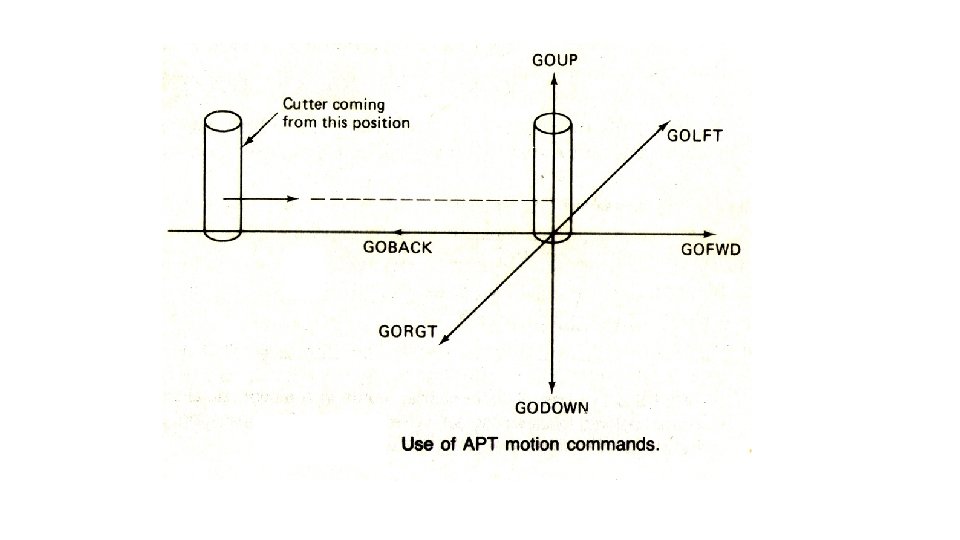
15. GODOWN: Go down. 16. GOFWD: Go forward. 17. GOLFT: Go left. 18. GORGT: Go right. 19. GOUP: Go up.
20. GOTO: Go to. • Used only for PTP motions. • Methods of specification: a) By using a previously defined point GOTO/P 1 b) By defining the coordinates of the point. GOTO /− 1. 0, 2. 0, 0. 0 GO/TO, LI, TO, PL 1, TO, L 6
21. INTOF: Intersection of. Indicates that intersection of two geometric element is the specified point. 22. LEFT: Left 23. RIGHT : Right Used to indicate which of the two alternatives, left or right is desired. 23. MACHIN: Machine Used to specify the machine tool and to call the processor for that machine tool. MACHIN / MILL, 1 post
24. LINE: Line Methods of specification: a. By coordinates of two points L 1 = LINE / 2, 1, 0, 5, 3, 0 b. By two points L 1 = LINE / P 1, P 2
24. LINE: Line c. By a point and tangent to a circle L 1 = LINE / P 1, LEFT, TANTO, C 1 L 2 = LINE / P 1, RIGHT, TANTO, C 1 LEFT & RIGHT are used by looking from the point towards the circle.
24. LINE: Line d. By a point and the axis L 3 = LINE / P 1, LEFT, ATANGL, 20 By a point and another line. L 4 = LINE / P 1, LEFT, ATANGL, 30, L 3
24. LINE: Line e. By a point and being parll to or perp. to another line. L 5 = LINE / P 2, PARLEL, L 3 L 6 = LINE / P 2, PERPTO, L 3
24. LINE: Line f. By being tangent to two circles. LEFT & RIGHT are used by looking from the first circle written towards the second circle.
25. PLANE: Used to define a plane Methods of specification: a. By three points that do not lie on the straight line. PL 1 = PLANE/ P 1, P 2, P 3 b. By a points and being parallel to another plane. PL 2 = PLANE/ P 4, PARLEL, PL 1
c. By a points and being perpendicular to another plane. PL 3 = PLANE, PERPTO, PL 1, P 5, P 6
26. POINT: Used to define a point Methods of specification: a. By x, y, z co-ordinates. P 1 = POINT/ 2. 5, 3. 5, 0 b. By intersection of two lines. P 4 = POINT/ INTOF, L 1, L 2 c. By intersection of line and circle. P 2 = POINT / YLARGE, INTOF, L 3, C 1 P 2 = POINT / XSMALL, INTOF, L 3, C 1 P 3 = POINT / XLARGE, INTOF, L 3, C 1 P 3 = POINT / YSMALL, INTOF, L 3, C 1
26. POINT: Used to define a point d. By center of a circle P 6 = POINT / CENTER, C 1 e. By intersection of two circles. P 4 = POINT / YLARGE, INTOF, C 1, C 2 P 4 = POINT / XSMALL, INTOF, C 1, C 2 P 5 = POINT / XLARGE, INTOF, C 1, C 2 P 5 = POINT / YSMALL, INTOF, C 1, C 2
27. RADIUS: Radius Used to define the radius of the circle 28. TANTO: Tangent to (Two uses) a. As descriptive data: used to indicate tangency of one geometric element to another. b. As a motion modifier: used to indicate that the tool motion is to terminate at the point of tangency between the drive surface and the check surface.
29. XLARGE: in the positive x direction. used to indicate the relative position of one geometric element with respect to another when there are two possibilities. 30. XSMALL: in the negative x direction. 31. YLARGE: in the positive y direction. 32. YSMALL: in the negative y direction.
Motion statement • Its general form is Motion command / descriptive data e. g. GOTO / P 1 FROM/P 1 It has two sections. • Basic motion command it tells the tool what to do • Descriptive data it tells the tool where to go
Motion statement • There are classified as : a) POINT-TO-POINT MOTIONS • They are used to specify the tool position. • There are only two PTP motion commands. GOTO and GODLTA • GOTO instructs the tool to go to particular point location specified in descriptive data. GOTO / P 4 GOTO / 2, 4, 0
Motion statement b) CONTOURING MOTIONS • There are six contouring motion commands. • GOLFT GORGT GOUP GODOWN GOFWD GOBACK • They are used to specify continuous path motion. • The tool is directed along two intersecting surfaces. • The third surface is the limiting surface for tool motion. • Drive surface • Part surface • Check surface
Motion statement • Drive surface • It is the surface that guides the path of the cutter. • It is the surface with which the tool is in continuous contact. • Part surface • It is in continuous contact with tool tip. • It helps to control the depth of cut. • Check surface • It limits the given motion statement.
Motion statement USE OF CHECK SURFACE • The check surface can be used in several ways. • It is determined by modifier words within the descriptive words. • TO , ON , PAST are three main modifier words. • TANTO is used when drive surface is tangent to check surface. • In such case cutter is brought to point of tangency with circle.
Post Processor statement • It controls the operation of machine • Only the words with / requires data. e. g. COOLNT / ON END FEDRAT / SPINDL /
Auxilliary statement • They are used for part identification, cutter size etc. e. g. PART NO / CUTTER / FINI / CLPRNT OUTTOL
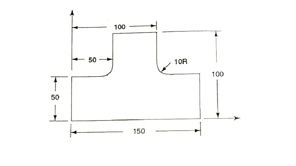
PART NO / 1212 MACHIN / MILLING 3 CLPRNT P 0 = POINT / 0 , -20 , 0 P 1 = POINT / 0 , 0 P 2 = POINT / 150 , 0 P 3 = POINT / 150 , 0 P 4 = POINT / 100 , 50 , 0 P 5 = POINT / 100 , 0 P 6 = POINT / 50 , 100 , 0 P 7 = POINT / 50 , 0 P 8 = POINT / 0 , 50 , 0
L 1 = LINE / P 1 , P 2 L 2 = LINE / P 2 , P 3 L 3 = LINE / P 3 , P 4 L 4 = LINE / P 4 , P 5 L 5 = LINE / P 5 , P 6 L 6 = LINE / P 6 , P 7 L 7 = LINE / P 7 , P 8 L 8 = LINE / P 8 , P 9 CUTTER / 10 SPINDL / 600 FEDRAT / 80 COOLNT / ON PL 1= PLANE / 0 , -20 , 150 , -20 , 100 , -20
FROM / P 0 GO / TO, L 1, TO, PL 1, TO, L 8 GORGT / L 1, PAST, L 2 GOUP / L 2, PAST, L 3 GOLFT/ L 3, TO, L 4 GOUP / L 4, PAST, L 5 GOLFT / L 5, PAST , L 6 GODOWN / L 6, TO, L 7 GOLFT / L 7, PAST, L 8 GODOWN / L 8, PAST, L 1 RAPID GOTO/ P 0 COOLNT / OFF FINI
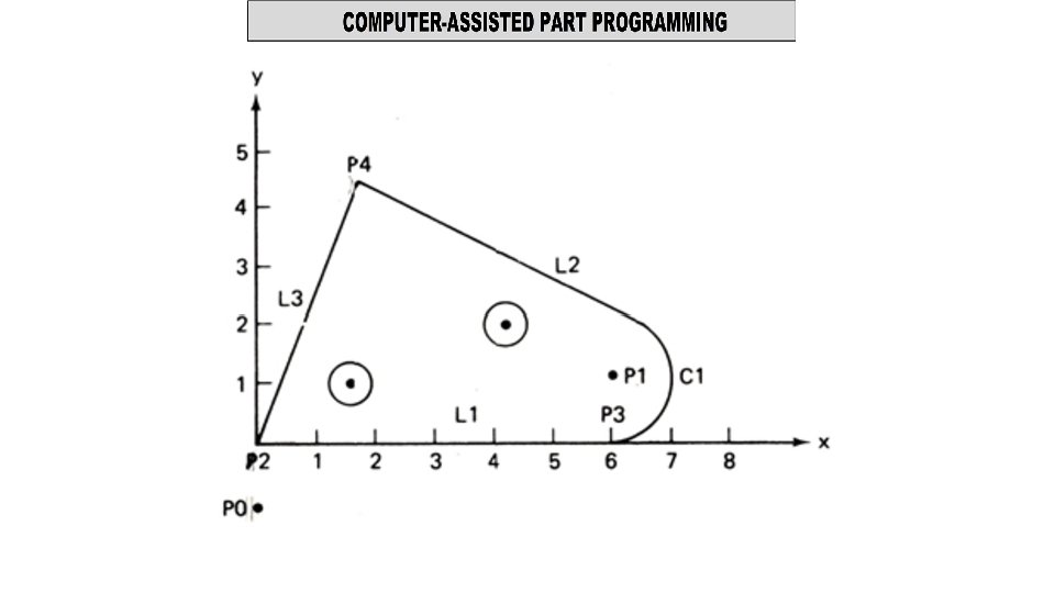
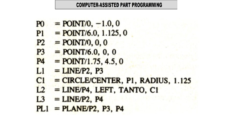
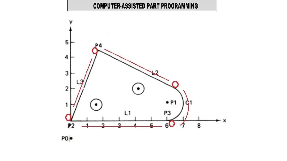
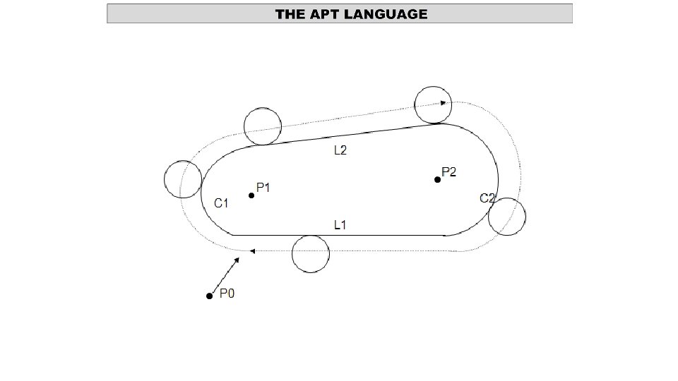
P 0 = POINT/ 0, -2, 0 P 1 = POINT/ 0. 312, 0 P 2 = POINT/ 4, 1, 0 C 1 = CIRCLE/ CENTER, P 1, RADIUS, 0. 312 C 2 = CIRCLE/ CENTER, P 2, RADIUS, 1 L 2 = LINE/ RIGHT, TANTO, C 2, RIGHT, TANTO, C 1 L 1 = LINE/ LEFT, TANTO, C 2, LEFT, TANTO, C 1 PL 1 = PLANE/ P 0, P 1, P 2 FROM/ P 0 GO/TO, L 1, TO, PL 1, TO, C 2 GOLFT/ L 1, TANTO, C 1 GOFWD/ C 1, PAST, L 2 GOFWD/ L 2, TANTO, C 2 GOFWD/ C 2, PAST, L 1 GOTO/ P 0
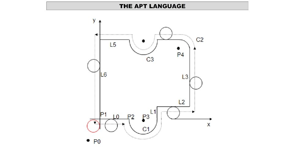
P 0 = POINT/ -1, 3 P 1 = POINT/ 0, 0 P 2 = POINT/ 3, 0 P 3 = POINT/ 4, 0 P 4 = POINT/ 6. 5, 5. 5 C 1 = CIRCLE/ CENTER, P 3, RADIUS, 1 L 0 = LINE/ P 1, P 2 L 1 = LINE/ (POINT/ 5, 1), LEFT, TANTO, C 1 L 2 = LINE/ (POINT/ 7, 1), PERPTO, L 1 C 2 = CIRCLE/ CENTER, P 4, RADIUS, 0. 5 L 3 = LINE/ (POINT/ 7, 1), RIGHT, TANTO, C 2 L 4 = LINE/ (POINT/ 5, 6), LEFT, TANTO, C 2 C 3 = CIRCLE/ CENTER, (POINT/ 4, 6), (POINT/ 3, 6) L 5 = LINE/ (POINT/ 0, 6), (POINT/ 3, 6) L 6 = LINE/ P 1, PERPTO, L 5 PL 1 = PLANE/ P 1, P 2, P 3
FROM/ P 0 GO/ TO, L 0, TO, PL 1, TO, L 6 GODLTA/ 0, 0, -1 GORGT/ L 0, TO, C 1 GORGT/ C 1, TANTO, L 1 GOFWD/ L 1, TO, L 2 GORGT/ L 2, PAST, L 3 GOLFT/ L 3, TANTO, C 2 GOFWD/ C 2, TANTO, L 4 GOFWD/ L 4, PAST, C 3 GOLFT/ C 3, PAST, L 5 GOLFT/ L 5, PAST, L 6 GOLFT/ L 6, PAST, L 0 GODLTA/ 0, 0, 1 GOTO/ P 0
MACRO STATEMENT • Symbol = MACRO / parameter defination e. g. TURN = MACRO / ZS • To call MACRO: CALL / symbol, parameter specification e. g. CALL / TURN, ZS = P 1 • To terminate MACRO TERMAC
MACRO PROGRAM TO DRILL HOLES
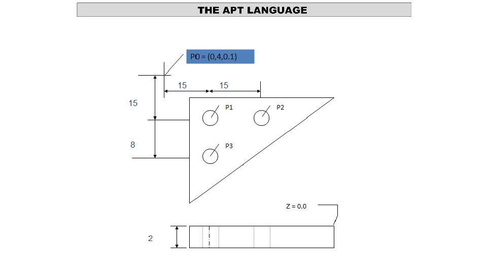
MACRO STATEMENT P 1 = POINT/ 1, 2, 0 P 2 = POINT/ 1, 1, 0 P 3 = POINT/ 3. 5, 1. 5, 0 PO = POINT/ -1, 3, 2 DRILL = MACRO/ PX GOTO/ PX GODELTA/ 0, 0, -1 GODELTA/ 0, 0, 1 TERMAC FROM/ PO CALL DRILL/ PX = P 1 CALL DRILL/ PX = P 2 CALL DRILL/ PX = P 3 GOTO/ PO
MACRO STATEMENT PO = POINT/ 0, 4, 0. 1 DELTA = MACRO/ DX GOTO/ DX GODELTA/ 1, 2, -3 GODELTA/ 1, 2, 3 TERMAC FROM/ PO CALL DELTA/ DX = P 1 CALL DELTA/ DX = P 2 GOTO/ PO
• CNC is designed to perform number of functions • Several of these functions would be either impossible or very difficult to accomplish with conventional NC. • The principal functions of CNC are: • Machine tool control • In-process compensation • Improved programming and operating features • Diagnostics
Machine tool control • Primary function of CNC is control of the machine tool. • Conversion of the PP instructions into motions through interface • Capability to incorporate variety of control features into the softwired controller unit is the main advantage of CNC. • Control functions, like G 02, can be accomplished more efficiently with hard-wired circuits than with the computer. • Two alternate controller design • Hybrid CNC • Straight CNC
Machine tool control Hybrid CNC • Controller consists of Soft and hard wired components • Hard wired governs feed rate, G 02 • Computer performs remaining functions. • Circuits performing hard wired functions are cheaply made. • Less expensive computer • Logic cannot be altered
Machine tool control Straight CNC • Uses only computer to perform all functions • Hard wire elements are only those required to interface. • More powerful computer required • Advantage is flexibility to changes
In-process compensation: • This function is closely related to machine tool control. • Some of the options included within this category are: • Adjustments for errors sensed by in-process inspection probes and gauges. • Re-computation of axis positions when inspection probe is used to locate a datum reference on a work part. • Offset adjustments for tool radius and length. • Adaptive control adjustments to speed and/or feed. • Computation of predicted tool life • Selection of alternative tooling when indicated.
Improved programming and operating features: • CNC has permitted many operating features like: • Editing of part programs at the machine. Permits optimization • Graphic display of the tool path. Verify the program • Various types of interpolation: circular, parabolic, and cubic • Use of specially written subroutines • Manual data input (MDI) • Local storage of more than one part program
Diagnostics: • NC machine tools are complex and expensive systems. • More Complexity --- risk of component failures---lead to downtime. • Personnel be trained to a higher level of proficiency to repair • Higher NC cost -- motivation to avoid downtime • Equipped with diagnostics capability to assist in maintenance a) Identify the reason for a downtime occurrence b) Alert to indicate failure of component. Predictive maintenance. c) Has certain amount of redundancy of components which are considered unreliable.
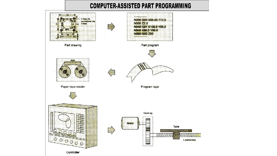
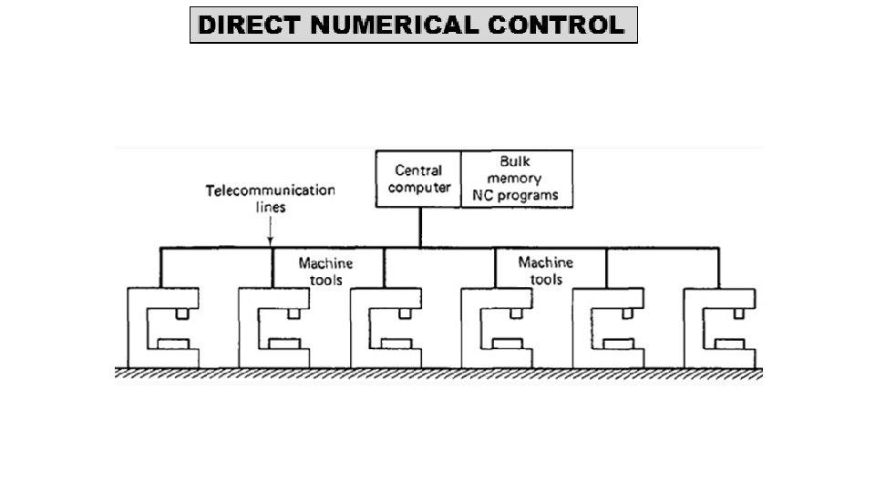
• Direct numerical control can be defined as • • • a manufacturing system in which a number of machines are controlled by a computer through direct connection and in real time. • The tape reader is omitted in DNC. • Instead, the part program is transmitted to the machine tool directly from the computer memory.
• Principle: • one large computer can be used to control more than 100 separate machines. • The DNC computer is designed to provide instructions to each machine tool on demand. • When the machine needs control commands, they are communicated to it immediately. • DNC also involves data collection and processing from the machine tool back to the computer.
Figure illustrates the configuration of the basic DNC system. A direct numerical control system consists of four basic components: • Central computer • Bulk memory, which stores the NC part programs • Telecommunication lines • Machine tools
Central computer • Function is to call and send part program to individual machines. • Also receive data back from machines • Does it through transmission lines • In real time Bulk memory • Stores all programs required for CNC machines.
Telecommunication lines • Cables that connect the machine tools. • RS 232 C connector. Machine tools • Different machines like milling, lathe, grinding etc.
• Satellite computers: • More machine tools • More requirement of data
• Satellite computers: • Mini computers - to take some burdens off the central computer. • Each satellite controls several machines. • Memory buffer of SC store part program instructions received from the central computer • They are then dispensed to the individual machines as required. • Feedback data from the machines are also stored in the satellite’s buffer before being collected at the central computer.
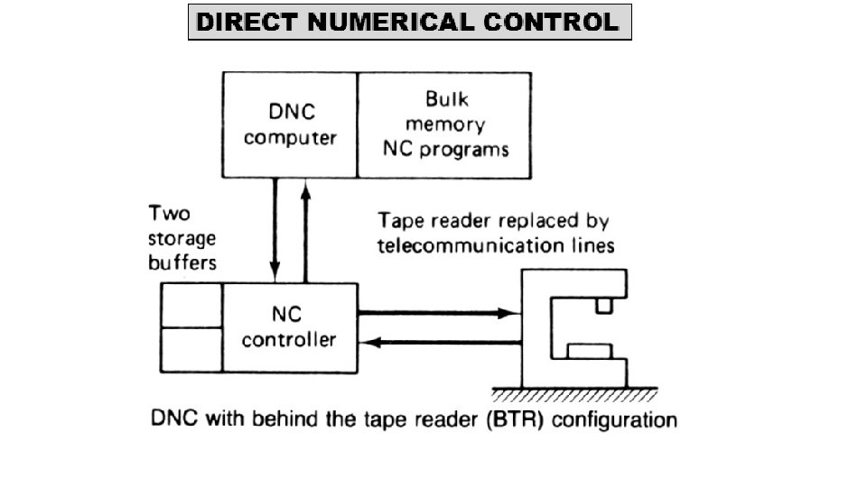
TWO TYPES OF DNC • There are two alternative system configurations by which the communication link is established between the control computer and the machine tool. • Behind-the-tape reader system • Special machine control unit.
Behind-the-Tape-Reader (BTR) System • Computer is linked directly to regular NC controller unit. • Replacement of tape reader by telecommunication lines to DNC computer is what gives BTR configuration it’s name. • Except for the source of the command instructions, the operation of the system is very similar to conventional NC. • Controller unit uses two temporary storage buffers to receive blocks of instructions from DNC computer and convert them into machine actions. • While one buffer is receiving a block of data, the other is providing command instructions to the machine tool.
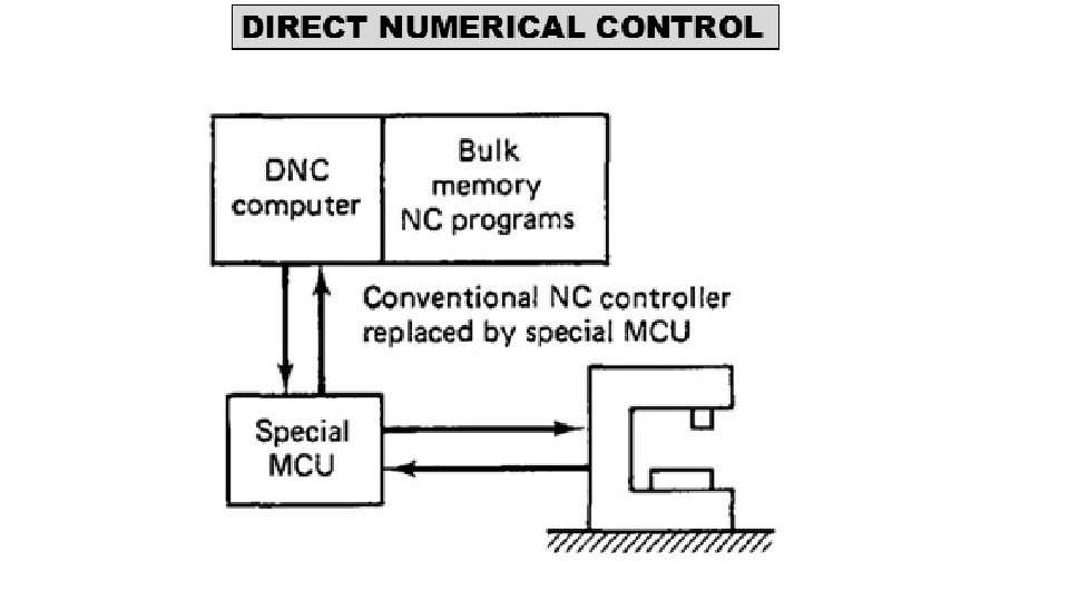
Special Machine Control Unit • Eliminate regular NC controller totally with special MCU. • MCU is a device that is specifically designed to facilitate communication between machine tool and computer. • One area where this communication link is important is in circular interpolation of the cutter path. • The special MCU configuration achieves a superior balance between accuracy of the interpolation and fast metal removal rates than is generally possible with the BTR system.
• The advantage of the BTR configurations is that its cost is less, since only minor changes are needed in conventional NC system to bring DNC into the shop. • BTR systems do not require the replacement of the conventional control unit by a special MCU. • But this BTR advantage is temporary since all virtual machines are sold with CNC. • The CNC controller serves the same purpose as a special MCU when incorporated into a DNC system.
Functions of DNC • There are several functions which a DNC system is designed to perform. • These functions are unique to DNC and could not be accomplished with either conventional NC or CNC. • The principal functions of DNC are: • NC without punched tape • NC part program storage • Data collection, processing, and reporting • Communications
Functions of DNC • NC without punched tape • Basic objective of DNC to eliminate punched tape • Many problems in NC because of punched tape • Fragile, editing problems etc. • Expense associated with equipment producing punched tape
Functions of DNC • NC part program storage • Program must be stored • Allow to edit existing program and enter new program • Accomplish post processing function • CLFILE must be converted into instructions for particular machine tool • System must perform management function
Functions of DNC • Data collection, processing, and reporting • Two way transfer of data • Machine tool to central computer • Basic purpose is to monitor production in factory • Data are collected on factors that measure performance of shop • Piece count, m/c utilizn, tool used
Functions of DNC • Communication • Needed to accomplish other three functions • Essential communication link are between following • Central computer and machine tool • CC and part programmer's terminal • CC and bulk memory
Advantages of DNC • Elimination of punched tapes and tape readers. • Greater computational capability and flexibility. • Examples of these functions include circular interpolation. • Convenient storage of NC part programs in computer files. • Reporting of shop performance. • Collects, process, and report production performance data from the NC machines. • Establishes the framework for the evolution of the future computer-automated factory.