Navigational Aid for a Blind Individual Electrical Computer

Navigational Aid for a Blind Individual Electrical/ Computer Engineering Team P 12015: Bob Evans Jackson Lamp David Sachenik David Yip P 12016: Curtis Beard Aalyia Shaukat David Taubman Oliver Wing
 Microcontroller Navigation Algorithm Schematics Magnetometer RFID")
Summary Introduction/Review Power Calculations Battery User Input (Keypad) Microcontroller Navigation Algorithm Schematics Magnetometer RFID Reader/Antenna/Tags Testing Procedures Bill of Materials

Our Navigation Aid Device

P 12015: Power Calculations Battery is 3. 7 V, 1000 m. A*hr, 3. 70 W*hr RFID Reader Motors MCU Magnetometer Keypad *Sum Voltage Output: 3. 3 V 1. 5796 W*hr 0. 021166667 W*hr 0. 047784 W*hr 0. 0913 W*hr 0. 083333333 W*hr 1. 823184 W*hr *For (10) 20 minute intervals of navigation

P 12016: Power Calculations Battery is 3. 7 V, 1100 m. A*hr, 4. 01 W*hr Min Usage (m. Ah) = Voltage Output: 3. 3 V 23. 3833 Min Usage (m. Wh ) = Average (m. Ah) = 239. 2648 Average (m. Wh) = 789. 5738 Worst Case (m. Wh) = 2458. 8234 Worst Usage (m. Ah) = 745. 098 77. 165 Total Power (m. W/hr) Total (m. W) Battery Life (%) Total hours of Life 23. 1495 77. 165 1. 8959 175. 8137 236. 8721 789. 5738 19. 3998 17. 1823 737. 6470 2458. 8234 60. 4133 5. 5175 *For (10) 20 minute intervals of navigation

P 12015: Battery PRT-00339 3. 7 V 1000 m. Ah 2. 09” x 1. 3” x 0. 225” 0. 770 oz 2 -pin JST-PH connector

P 12016: Battery Tenergy Li-ion 17500 3. 7 V 1100 m. Ah 0. 71” x 2. 09” (Diameter x Height) 1. 04 oz. Molex 51021 2 -Pin Connector

Comparison of Voltage Regulation output and POK – Threshold Reached Indicator 4 3. 5 Output Voltage [V] 3 Regulated Output 2. 5 2 POK 1. 5 1 0. 5 0 2 2. 4 2. 6 2. 8 3 3. 2 Battery Voltage [V] 3. 4 3. 6 3. 8 4
 7 Pin Connection Contact rating: 20 m. A, 24 VDC 2.")
User Input (Keypad) 7 Pin Connection Contact rating: 20 m. A, 24 VDC 2. 52” L x 2. 01” W x 0. 28” H 0. 26 ounces Output Pin No. Symbol 1 ROW 1 2 ROW 2 3 ROW 3 4 ROW 4 5 COL 1 6 COL 2 7 COL 3

Microcontroller Selection Flow Chart Memory Usage Clock Speeds Approx. Number of Instructions processes for algorithm

Program Flow

Path Finding Algorithm

Path Following Algorithm
![Navigation Algorithm w = g->edges[v][i]. v; weight = g->edges[v][i]. weight; if (distance[w] > (distance[v]+weight))](http://slidetodoc.com/presentation_image/cb324799ae256bb3b927cc7df3b946e8/image-14.jpg "Navigation Algorithm w = g->edges[v][i]. v; weight = g->edges[v][i]. weight; if (distance[w] > (distance[v]+weight))")
Navigation Algorithm w = g->edges[v][i]. v; weight = g->edges[v][i]. weight; if (distance[w] > (distance[v]+weight)) { distance[w] = distance[v]+weight; parent[w] = v; } /* performs dijkstras algorithm upon the building graph */ "dijkstra(graph *g, int start) { int i, j; bool intree[MAXV]; int distance[MAXV]; int v; int weight; int dist; for (i=1; i<=g->nvertices; i++) { intree[i] = FALSE; distance[i] = MAXINT; parent[i] = -1; } distance[start] = 0; v = start; while (intree[v] == FALSE) { intree[v] = TRUE; for (i=0; i<g->degree[v]; i++) { } v = 1; dist = MAXINT; for (i=1; i<=g->nvertices; i++) if ((intree[i] == FALSE) && (dist > distance[i])) { dist = distance[i]; v = i; } } }

Navigation Algorithm Time Calculation

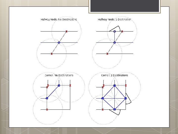
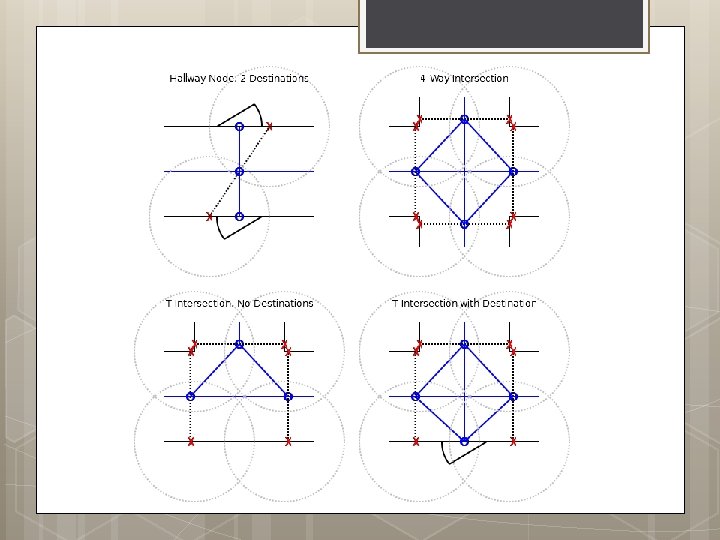
Mapping Data Structures RFIDTag Representation of an RFID tag. May be implemented as a 64 bit integer. Tags are stored in an array in FLASH and are referenced with an index value. Static. Node Basic node in a map graph. Composed of multiple RFIDTags, destinations, and references to other Nodes using Node. Vectors. Static. Nodes are stored in an array FLASH and are referenced with an index value. Elements num. Tags: The number of tags referenced by this Node. tags: The array of RFIDTag indicies referenced by this Node. num. Destinations: The number of destinations associated with this Node. destinations: The array of destinations associated with this Node. num. Nodes: The number of Node. Vectors leading to other nodes associated with this Node. nodes: The array of Node. Vectors leading to other nodes associated with this Node.

Mapping Data Structures Nodes are used as proxies to the Static. Node structures held in ROM. They consist of an index value which is used to identify the Static. Node they correspond to as well as a “visited” bit which is used by both the path finding and path following algorithms. An array of these is loaded into memory on system startup in an array which mimics the Static. Node array. Elements node: The index of the Static. Node this Node represents. visited: The visited status of the node. Node. Vector Represents a link from one node to another. Includes heading and distance information, which is used to determine edge costs in the navigation algorithm and to direct the user during the path following stage. Elements node: The index of the Node referenced by this Node. Vector. heading: The direction of the referenced node. distance: The distance to the referenced node.

Mapping Data Structures Destination Structure representing a destination using an integer identifier and a heading/distance vector. Elements id: The room number or other identification code of the Destination. heading: The direction of the Destination from the host Node. distance: The distance to the Destination from the host Node.

Mapping Data Structures
 Extra Size (b) Instances in RAM Instances")
Memory Requirement Estimate Structure Struct Size (b) Extra Size (b) Instances in RAM Instances in ROM Size in RAM (B) Size in ROM (B) RFIDTag 64 0 300 0 2400 Static. Node 48 112 160 0 150 0 3000 Node 16 0 16 1350 0 2700 0 Node. Vector 48 0 900 0 5400 Destination 48 0 300 0 1800 Total 2700 12600 Tags Tag: Node Ratio Avg. Branches: Node Avg. Dest: Node Max Branches in Map 300 2 3 2 8

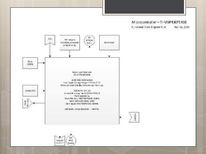
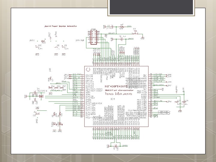
MCU Specs TI MSP 430 F 5438 A 16 -bit ISA 25 MHz Clock 16 KB SRAM/256 KB FLASH 8 USCI interfaces with support for SPI, I 2 C, and other serial protocols 18 Programmable PWM Outputs Extremely low power operation— 1. 05 m. W to 35 m. W active mode, 1. 1 μW to 300 μW sleep mode

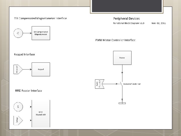
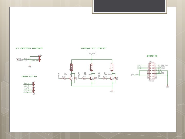
Magnetometer ST Micro Electronics LSM 303 DLH Tilt Compensated Compass Supply Voltage 3. 3 V Current in Operating Mode 0. 83 m. A 16 -bit data out I 2 C serial interface

RFID Antenna/Reader/Tags Hper. Link Wireless 900 MHz 8 d. Bi Flat Patch Antenna (HG 908 P) Skytek M 9 Module Alien Briggs Tag Type ALN-9640 Squiggle Inlay

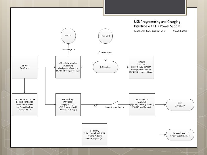
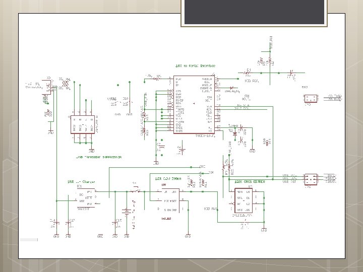
Block Diagrams/Schematic USB Interface with Microcontroller USB Transient Suppressor USB Charging Circuit Linear Regulator Keypad RFID Reader PWM (Motors) Magnetometer

Testing Procedures Battery & PCB Keypad MCU Magnetometer RFID Reader
 will be placed in the PCB to")
Battery & PCB testing Test Points (TPs) will be placed in the PCB to verify functionality. Voltage of test points will be measured and compared with their theoretical values. When the battery is fully charged, all test points should be within +/- 10% of theoretical value.
![Example of a TP Table Test Point (TP) Theoretical Value [V] TP 1 3.](http://slidetodoc.com/presentation_image/cb324799ae256bb3b927cc7df3b946e8/image-35.jpg "Example of a TP Table Test Point (TP) Theoretical Value [V] TP 1 3.")
Example of a TP Table Test Point (TP) Theoretical Value [V] TP 1 3. 7 TP 2 3. 3 Measured Value (When battery is fully charged, falls within +/- 10% of theoretical) [V]

Keypad Testing Input Room Numbers/Destinations -Monitor MCU data collection -Feedback from vibrating motors Powering on/off

MCU Testing When possible, testing is performed while debugging the MCU. Navigation algorithm will be tested in the following cases: Known tag ID and destination supplied; path returned in < 1 s. Known tag ID and unknown destination supplied; failure reported in < 1 s. Unknown tag ID and known destination supplied; failure reported in < 1 s. Interfaces with other devices will be tested individually prior to the code being integrated with the main program.
 -Flat")
Magnetometer Tests Correct indication of Northern Direction -With/Without interference (Different areas within building) -Flat surface vs. Tilted at various angles -Walking motion test Data interface with microcontroller Power consumption test Heat Dissipation

RFID Reader/Antenna Tests Antenna Position/Polarity Read distance Optimal reading angles Read Time Power Consumption Test Heat Dissipation

P 12015: Bill of Materials Type Part 900 MHz 8 d. Bi Flat Patch Antenna - 4 ft SMA Male Component Connecto Precision Haptic 10 mm Vibration Motor - 15 mm Component Type model 1 Precision Haptic 10 mm Vibration Motor - 15 mm Component Type model 2 Manufactuer Manufacturer Part # Quantity Unit Price Shipping Cost Total Cost ($) L-com Global Connectivity HG 908 P-SM 1 $54. 99 Precision Microdrives 310 -001 3 $7. 56 $22. 68 Precision Microdrives 310 -002 2 $7. 56 $15. 12 Component Pico Vibe 12 mm Vibration Motor - 3. 4 mm Type Precision Microdrives 312 -101 3 D Compass and Accelerometer Carrier with Voltage Pololu Robotics & Component Regulators Electronics LSM 303 DLH 1 $6. 48 $17. 97$24. 45 1 $19. 95 Component LSM 303 DLH Tilt Compensated Compass Chip ST Micro Electronics COM-09757 1 $6. 95 3. 86$10. 81 Component Polymer Lithium Ion Battery - 1000 m. Ah Sparkfun Electronics PRT-00339 1 $11. 95 Component 16 -Bit Ultra-Low-Power Microcontroller Texas Instruments MSP 430 F 5438 A 1 $12. 13 Component Small Keypad Futurlec Electronics KEYPADSM 1 $2. 20 Component Skye. Module M 9 Skye. Tek M 9 V. 080527 Component PCB 1 $300. 00 Component IC BATT CHRGR LI+ 1 CELL MAXIM 2 $2. 37 $4. 74 Component IC REG LDO 3. 3/ADJ 500 MA MAXIM MAX 1555 EZK+TC T-ND MAX 1818 EUT 33+ T 2 $3. 25 $6. 50 Component IC USB FS SERIAL UART FTDI FT 232 RL 2 $4. 50 $9. 00 Case Rod, ABS, Beige, 1 In Dia x 1 Ft L Grainger 1 ZBU 6 1 $8. 59 Case RIT - 1. 998 $10. 00 $10. 95$65. 94 $4. 00$6. 20 $300. 00 $19. 98 Total Cost: $538. 04

P 12016: Bill of Materials

? Questions
- Slides: 42