
n Ge AM ab le m ra og
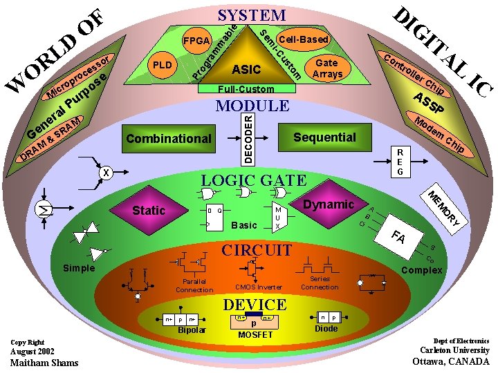
n Ge AM & ab le m ra og Pr rp u P A SR ntr oll Full-Custom M Combinational DR X Ch ip A FA Y Ci B OR CMOS Inverter m EM Dynamic S Co Simple Parallel Connection P R E G CIRCUIT IC M M U X Basic ip de Sequential D Q Ch Mo LOGIC GATE Static er AL AS S MODULE DECODER al r e m to Mi ASIC IT Co Gate Arrays us W PLD Cell-Based i-C R ce o r O crop ose r o ss m FPGA m F O Se D L DI G SYSTEM Series Connection Complex DEVICE n+ p n+ Bipolar Copy Right August 2002 Maitham Shams n+ n+ p MOSFET n p Diode Dept of Electronics Carleton University Ottawa, CANADA
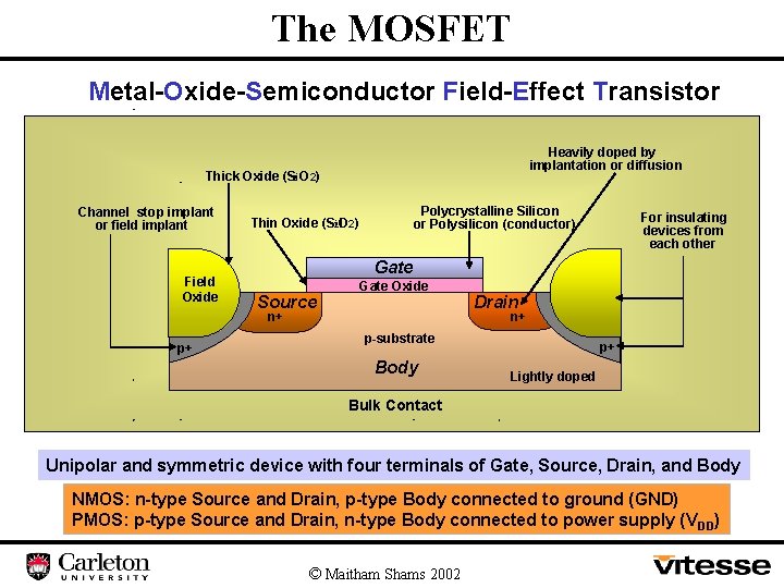
The MOSFET Metal-Oxide-Semiconductor Field-Effect Transistor Heavily doped by implantation or diffusion Thick Oxide (S 2 i. O 2) Channel stop implant or field implant Field Oxide Polycrystalline Silicon or Polysilicon (conductor) ) 2) Thin Oxide (S 2 i. O Gate Source Gate Oxide n+ p+ For insulating devices from each other Drain n+ p-substrate Body p+ Lightly doped Bulk Contact Unipolar and symmetric device with four terminals of Gate, Source, Drain, and Body NMOS: n-type Source and Drain, p-type Body connected to ground (GND) PMOS: p-type Source and Drain, n-type Body connected to power supply (V DD) © Maitham Shams 2002
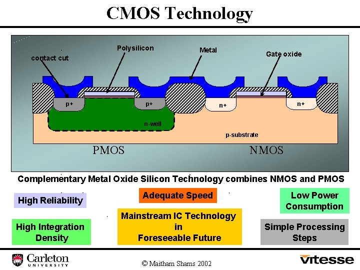
CMOS Technology Polysilicon Metal Gate oxide contact cut p+ p+ n+ n+ n-well p-substrate PMOS NMOS Complementary Metal Oxide Silicon Technology combines NMOS and PMOS High Reliability High Integration Density Adequate Speed Mainstream IC Technology in Foreseeable Future © Maitham Shams 2002 Low Power Consumption Simple Processing Steps
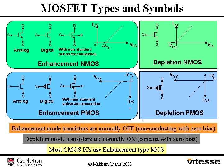
MOSFET Types and Symbols I DS 0 Analog Digital With non standard substrate connection +V Tn VGS -VTn Depletion NMOS Enhancement NMOS G G S Analog Digital VGS D D VGS 0 -V Tp D 0 B VGS 0 +V Tp G S With non standard substrate connection I DS Enhancement PMOS S I DS Depletion PMOS Enhancement mode transistors are normally OFF (non-conducting with zero bias) Depletion mode transistors are normally ON (conduct with zero bias) Most CMOS ICs use Enhancement type MOS © Maitham Shams 2002
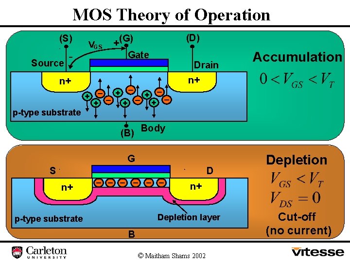
MOS Theory of Operation (S) Source - VGS n+ + p-type substrate _ + (D) +(G) Gate _ + _ + (B) Drain _ + n+ _ Body G S n+ _ _ _ D Depletion n+ Depletion layer p-type substrate Accumulation B © Maitham Shams 2002 Cut-off (no current)
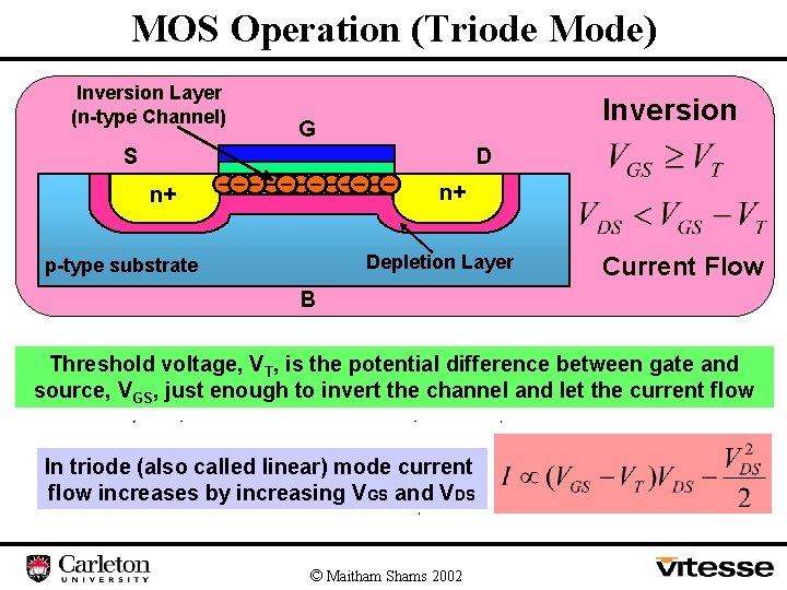
MOS Operation (Triode Mode) Inversion Layer (n-type Channel) S n+ Inversion G _ _ _ _ __ _ _ D n+ Depletion Layer p-type substrate Current Flow B Threshold voltage, VT, is the potential difference between gate and source, VGS, just enough to invert the channel and let the current flow In triode (also called linear) mode current flow increases by increasing VGS and VDS © Maitham Shams 2002
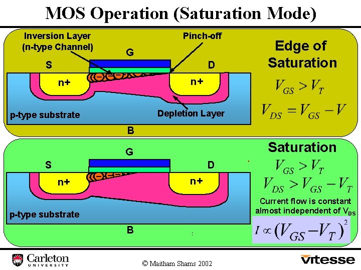
MOS Operation (Saturation Mode) Inversion Layer (n-type Channel) S n+ Pinch-off G _____ _ _ _ ______ D Edge of Saturation n+ Depletion Layer p-type substrate B Saturation G S n+ _____ _ _ _ ______ D n+ Current flow is constant almost independent of VDS p-type substrate B © Maitham Shams 2002
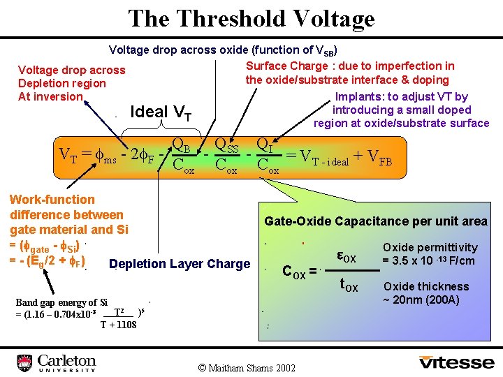
The Threshold Voltage drop across oxide (function of VSB) Surface Charge : due to imperfection in Voltage drop across the oxide/substrate interface & doping Depletion region At inversion Implants: to adjust VT by introducing a small doped region at oxide/substrate surface Ideal VT VT = ms - 2 F - QB QSS QI Cox Cox = VT - ideal + VFB Work-function difference between gate material and Si = ( gate - Si) = - (Eg/2 + F) Depletion Layer Charge Gate-Oxide Capacitance per unit area COX = Band gap energy of Si T 2 )5 = (1. 16 – 0. 704 x 10 -3 T + 1108 © Maitham Shams 2002 OX t. OX Oxide permittivity = 3. 5 x 10 -13 F/cm Oxide thickness ~ 20 nm (200 A)
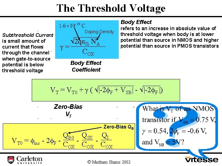
The Threshold Voltage Body Effect Subthreshold Current is small amount of current that flows through the channel when gate-to-source potential is below threshold voltage Doping Density 2 q Si NA = COX refers to an increase in absolute value of threshold voltage when body is at lower potential than source in NMOS and higher potential than source in PMOS transistors Body Effect Coefficient VT = VT 0 + ( |-2 F + VSB| - |-2 F |) Zero-Bias VT Zero-Bias QB QB 0 QSS QI VT 0 = ms - 2 F - C - C OX OX OX © Maitham Shams 2002
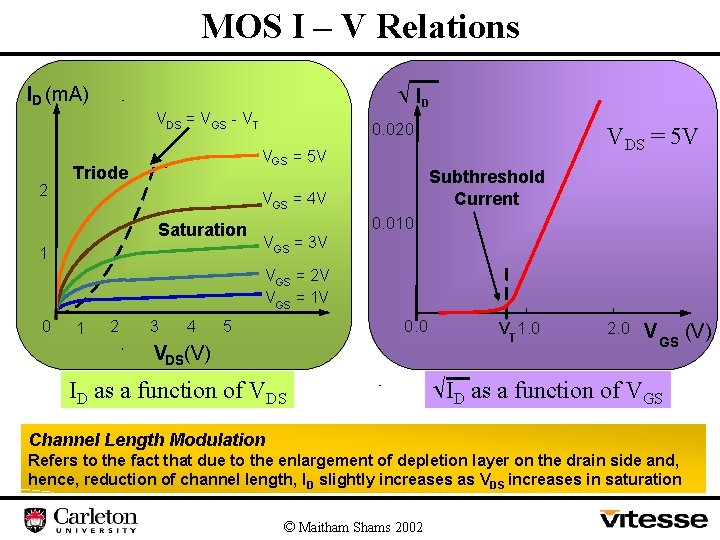
MOS I – V Relations ID ID (m. A) VDS = V GS - V T 2 0. 020 VGS = 5 V Triode Subthreshold Current VGS = 4 V Saturation 1 VDS = 5 V 0. 010 VGS = 3 V VGS = 2 V VGS = 1 V 0 1 2 3 4 0. 0 5 VDS(V) ID as a function of VDS VT 1. 0 2. 0 V GS ID as a function of VGS Channel Length Modulation Refers to the fact that due to the enlargement of depletion layer on the drain side and, hence, reduction of channel length, ID slightly increases as VDS increases in saturation © Maitham Shams 2002 (V)
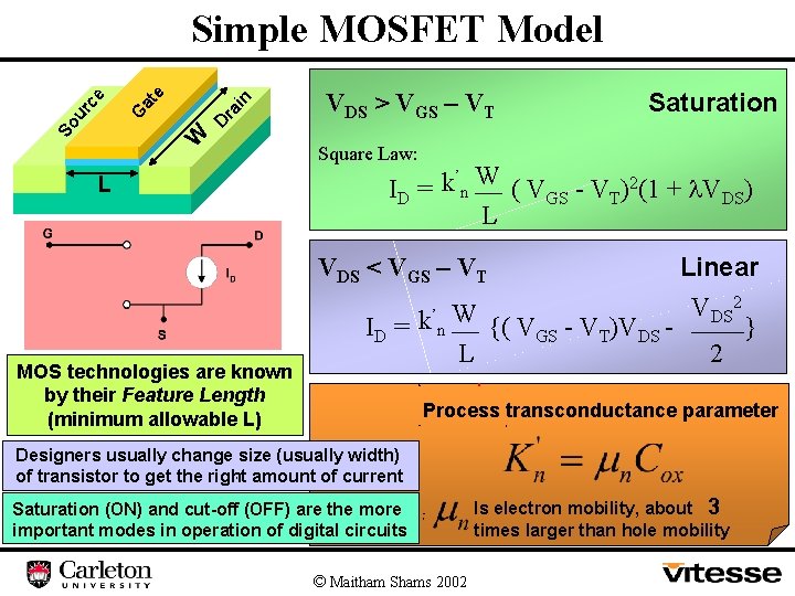
ra in at e D W So G ur c e Simple MOSFET Model L VDS > VGS – VT Saturation Square Law: ’ ID = k n W ( VGS - VT)2(1 + VDS) L Linear VDS 2 ’ W ID = k n {( VGS - VT)VDS } L 2 VDS < VGS – VT MOS technologies are known by their Feature Length (minimum allowable L) Process transconductance parameter Designers usually change size (usually width) of transistor to get the right amount of current Saturation (ON) and cut-off (OFF) are the more important modes in operation of digital circuits © Maitham Shams 2002 Is electron mobility, about 3 times larger than hole mobility
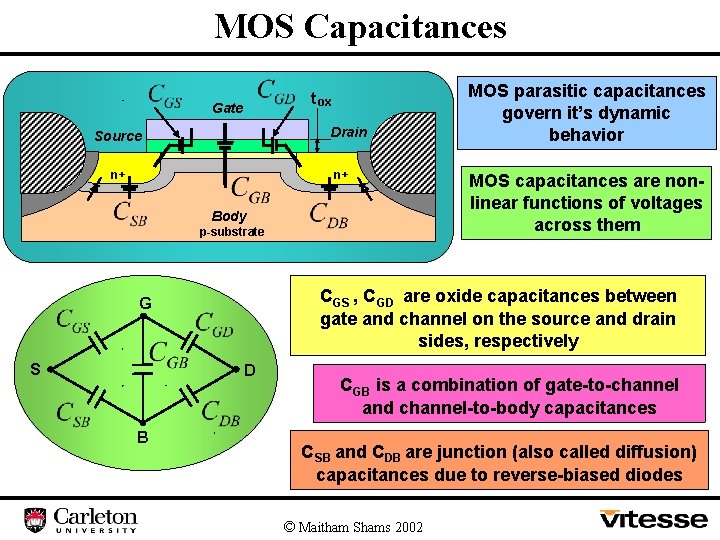
MOS Capacitances t ox Gate Drain Source n+ n+ MOS capacitances are nonlinear functions of voltages across them Body p-substrate c. GS , c. GD are oxide capacitances between gate and channel on the source and drain sides, respectively G S MOS parasitic capacitances govern it’s dynamic behavior D c. GB is a combination of gate-to-channel and channel-to-body capacitances B c. SB and c. DB are junction (also called diffusion) capacitances due to reverse-biased diodes © Maitham Shams 2002
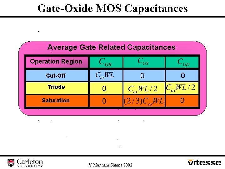
Gate-Oxide MOS Capacitances Average Gate Related Capacitances Operation Region 0 Cut-Off Triode 0 Saturation 0 © Maitham Shams 2002 0 0
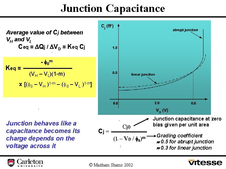
Junction Capacitance Average value of Cj between VH and VL Ceq = Qj / VD = Keq Cj Keq = - 0 m (VH – VL)(1 -m) x [( 0 – VH )1 -m – ( 0 – VL )1 -m] Junction behaves like a capacitance becomes its charge depends on the voltage across it Cj = Cj 0 (1 – VD / 0)m © Maitham Shams 2002 Junction capacitance at zero bias given per unit area Grading coefficient 0. 5 for abrupt junction 0. 3 for linear junction
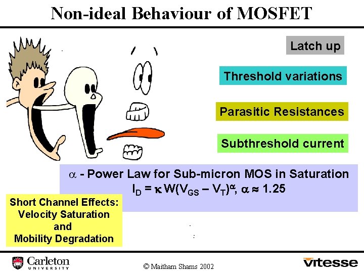
Non-ideal Behaviour of MOSFET Latch up Threshold variations Parasitic Resistances Subthreshold current a - Power Law for Sub-micron MOS in Saturation ID = k W(VGS – VT) , 1. 25 Short Channel Effects: Velocity Saturation and Mobility Degradation © Maitham Shams 2002
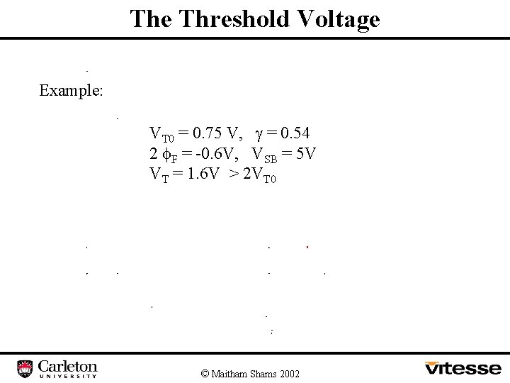
The Threshold Voltage Example: VT 0 = 0. 75 V, = 0. 54 2 F = -0. 6 V, VSB = 5 V VT = 1. 6 V > 2 VT 0 © Maitham Shams 2002
- Slides: 16