MULTIPLEXING AND MULTIPLE ACCESS UNIT V Multiplexing And


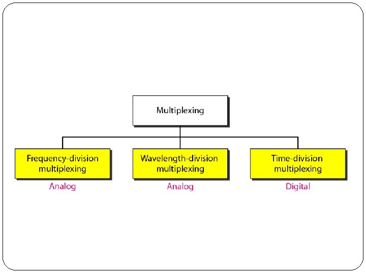
 � Frequency-division multiplexing (FDM) is an analog technique that can")


 �Wavelength-division multiplexing (WDM) is designed to use the high-data-rate capability")


, can multiplex a very large number of")
 �Time-division multiplexing (TDM) is a digital process that allows several")


 � Multiplexing combines signals from several sources to achieve bandwidth efficiency; the")


 � The frequency hopping spread spectrum (FHSS) technique")
 �This technique also expands the bandwidth of the")


 � The chance of collision can be reduced if")


 �In this method, a station monitors")


 �In frequency-division multiple access (FDMA), the available bandwidth is")

 �In time-division multiple access (TDMA), the stations share the")

 �CDMA differs from FDMA because only one channel occupies")


- Slides: 78
MULTIPLEXING AND MULTIPLE ACCESS UNIT V
Multiplexing And Multiple Access � Multiplexing: FDM, TDM, Synchronous Time-Division Multiplexing, Statistical Time-Division Multiplexing, WDM, Spread Spectrum: FHSS and DSSS � Random access: ALOHA, CSMS/CD and CSMA/ CA � Controlled Access: Reservation, Polling and Token Passing � Channelization: FDMA, TDMA and CDMA
Multiplexing
Multiplexing � In real life, we have links with limited bandwidths. � Sometimes we need to combine several low- bandwidth channels to make use of one channel with a larger bandwidth. � Sometimes we need to expand the bandwidth of a channel to achieve goals such as privacy and antijamming. � Whenever the bandwidth of a medium linking two devices is greater than the bandwidth needs of the devices, the link can be shared. � Multiplexing is the set of techniques that allows the simultaneous transmission of multiple signals across a single data link.
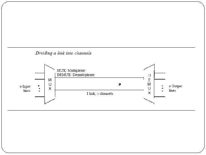
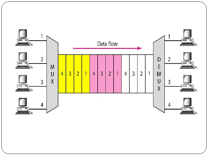
� In a multiplexed system, n lines share the bandwidth of one link. � The lines on the left direct their transmission streams to a multiplexer (MUX), which combines them into a single stream (many-to one). � At the receiving end, that stream is fed into a demultiplexer (DEMUX), which separates the stream back into its component transmissions (one-to-many) and directs them to their corresponding lines. � In the figure, the word link refers to the physical path. � The word channel refers to the portion of a link that carries a transmission between a given pair of lines. � One link can have many (n) channels.
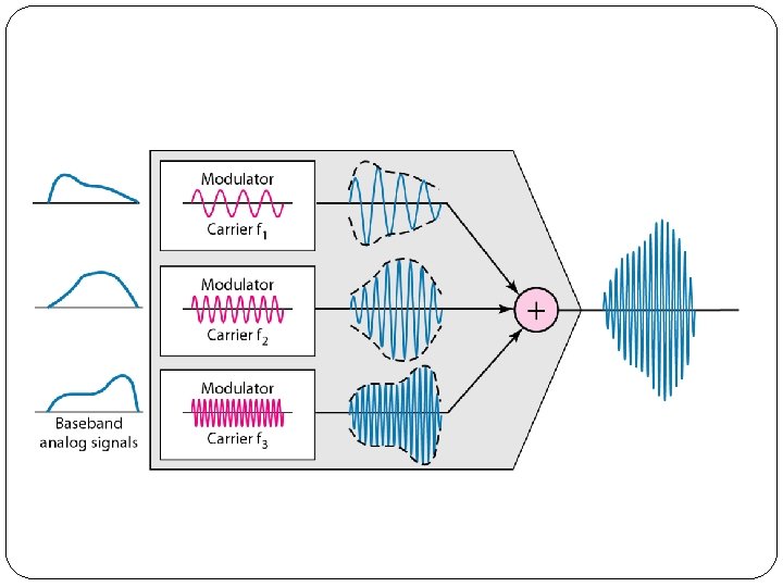
1. Frequency-Division Multiplexing (FDM) � Frequency-division multiplexing (FDM) is an analog technique that can be applied when the bandwidth of a link (in hertz) is greater than the combined bandwidths of the signals to be transmitted. � In FDM, signals generated by each sending device modulate different carrier frequencies. � These modulated signals are then combined into a single composite signal that can be transported by the link. � Carrier frequencies are separated by sufficient bandwidth to accommodate the modulated signal. � These bandwidth ranges are the channels through which the various signals travel. � Channels can be separated by strips of unused bandwidth-guard bands-to prevent signals from overlapping.
Multiplexing Process �Inside the multiplexer, these similar signals modulates different carrier frequencies (/1, 12, and h). �The resulting modulated signals are then combined into a single composite signal that is sent out over a media link that has enough bandwidth to accommodate it.
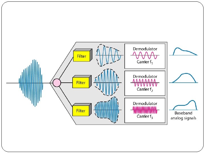
Demultiplexing Process �The demultiplexer uses a series of filters to decompose the multiplexed signal into its constituent component signals. �The individual signals are then passed to a demodulator that separates them from their carriers and passes them to the output lines.
Analog hierarchy
� In this analog hierarchy, 12 voice channels are multiplexed onto a higher-bandwidth line to create a group. � A group has 48 k. Hz of bandwidth and supports 12 voice channels. � At the next level, up to five groups can be multiplexed to create a composite signal called a supergroup. � A supergroup has a bandwidth of 240 k. Hz and supports up to 60 voice channels. � Supergroups can be made up of either five groups or 60 independent voice channels. � At the next level, 10 supergroups are multiplexed to create a master group. � A master group must have 2. 40 MHz of bandwidth, but the need for guard bands between the supergroups increases the necessary bandwidth to 2. 52 MHz. � Master groups support up to 600 voice channels. � Finally, six master groups can be combined into a jumbo group. � A jumbo group must have 15. 12 MHz (6 x 2. 52 MHz) but is augmented to 16. 984 MHz to allow for guard bands between the
2. Wavelength-Division Multiplexing (WDM) �Wavelength-division multiplexing (WDM) is designed to use the high-data-rate capability of fiber-optic cable. �The optical fiber data rate is higher than the data rate of metallic transmission cable. �Using a fiber-optic cable for one single line wastes the available bandwidth. �Multiplexing allows us to combine several lines into one.
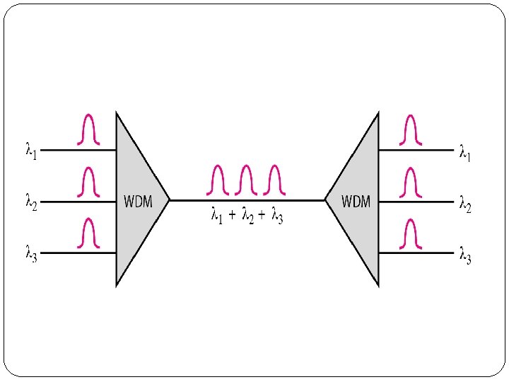
� WDM is conceptually the same as FDM, except that the multiplexing and demultiplexing involve optical signals transmitted through fiber-optic channels. � The idea is the same: We are combining different signals of different frequencies. � The difference is that the frequencies are very high. � Figure gives a conceptual view of a WDM multiplexer and demultiplexer. � Very narrow bands of light from different sources are combined to make a wider band of light. � At the receiver, the signals are separated by the demultiplexer.
�We want to combine multiple light sources into one single light at the multiplexer and do the reverse at the demultiplexer. �The combining and splitting of light sources are easily handled by a prism. �Using this technique, a multiplexer can be made to combine several input beams of light, each containing a narrow band of frequencies, into one output beam of a wider band of frequencies. �A demultiplexer can also be made to reverse the process.
Prisms in wavelength-division multiplexing and demultiplexing
�A new method, called dense WDM (DWDM), can multiplex a very large number of channels by spacing channels very close to one another. �It achieves even greater efficiency.
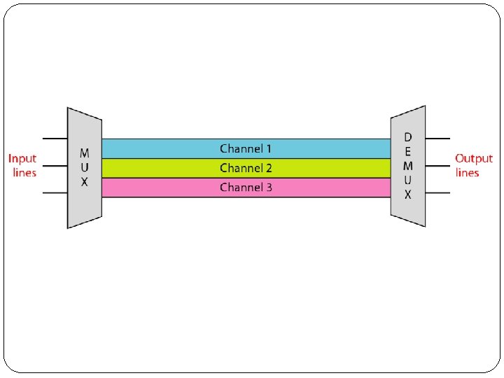
3. Time-Division Multiplexing (TDM) �Time-division multiplexing (TDM) is a digital process that allows several connections to share the high bandwidth of a link Instead of sharing a portion of the bandwidth as in FDM, time is shared. �Each connection occupies a portion of time in the link. �Figure gives a conceptual view of TDM. �Note that the same link is used as in FDM; here, however, the link is shown sectioned by time rather than by frequency. �In the figure, portions of signals 1, 2, 3, and 4
�Digital data from different sources are combined into one timeshared link. �However, this does not mean that the sources cannot produce analog data; analog data can be sampled, changed to digital data, and then multiplexed by using TDM. �We can divide TDM into two different schemes: synchronous and statistical.
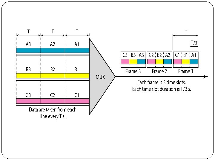
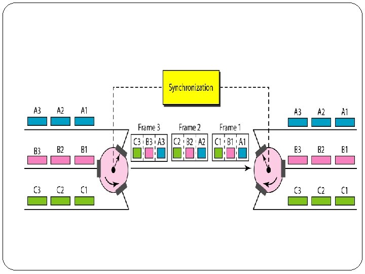
3. 1 Synchronous TDM �In synchronous TDM, the data flow of each input connection is divided into units, where each input occupies one input time slot. �A unit can be 1 bit, one character, or one block of data. �Each input unit becomes one output unit and occupies one output time slot. �However, the duration of an output time slot is n times shorter than the duration of an input time slot. �Figure shows an example of synchronous TDM where n is 3.
�In synchronous TDM, a round of data units from each input connection is collected into a frame (we will see the reason for this shortly). �If we have n connections, a frame is divided into n time slots and one slot is allocated for each unit, one for each input line. �If the duration of the input unit is T, the duration of each slot is Tin and the duration of each frame is T �In synchronous TDM, the data rate of the link is n times faster, and the unit duration is n times shorter.
Interleaving � TDM can be visualized as two fast-rotating switches, one on the multiplexing side and the other on the demultiplexing side. � The switches are synchronized and rotate at the same speed, but in opposite directions. � On the multiplexing side, as the switch opens in front of a connection, that connection has the opportunity to send a unit onto the path. � This process is called interleaving. � On the demultiplexing side, as the switch opens in front of a connection, that connection has the opportunity to receive a unit from the path.
Empty slots
3. 2 Statistical TDM � In synchronous TDM, each input has a reserved slot in the output frame. � This can be inefficient if some input lines have no data to send. � In statistical time-division multiplexing, slots are dynamically allocated to improve bandwidth efficiency. � Only when an input line has a slot's worth of data to send is it given a slot in the output frame. � In statistical multiplexing, the number of slots in each frame is less than the number of input lines. � The multiplexer checks each input line in round robin fashion; it allocates a slot for an input line if the line has data to send; otherwise, it skips the line and checks the next line. � Figure shows a synchronous and a statistical TDM example. � In the former, some slots are empty because the corresponding line does not have data to send.
TDM slot comparison
Spread Spectrum(SS) � Multiplexing combines signals from several sources to achieve bandwidth efficiency; the available bandwidth of a link is divided between the sources. � In spread spectrum, we also combine signals from different sources to fit into a larger bandwidth, but our goals are somewhat different. � Spread spectrum is designed to be used in wireless applications � (LANs and WANs). In these types of applications, we have some concerns that outweigh bandwidth efficiency. � In wireless applications, all stations use air (or a vacuum) as the medium for communication. � Stations must be able to share this medium without interception by an eavesdropper and without being subject to jamming from a malicious intruder
�To achieve these goals, spread spectrum techniques add redundancy; they spread the original spectrum needed for each station. �If the required bandwidth for each station is B, spread spectrum expands it to Bss such that Bss » B. �The expanded bandwidth allows the source to wrap its message in a protective envelope for a more secure transmission. �Spread spectrum achieves its goals through two principles: �The bandwidth allocated to each station needs to be, by far, larger than what is needed. This allows redundancy. �The expanding of the original bandwidth B to the bandwidth Bss must be done by a process that is independent of the original signal. In other words, the spreading process occurs after the signal is
Spread spectrum
�After the signal is created by the source, the spreading process uses a spreading code and spreads the bandwidth. �The figure shows the original bandwidth B and the spreaded bandwidth Bss. �The spreading code is a series of numbers that look random, but are actually a pattern. �There are two techniques to spread the bandwidth: frequency hopping spread spectrum (FHSS) and direct sequence spread spectrum (DSSS).
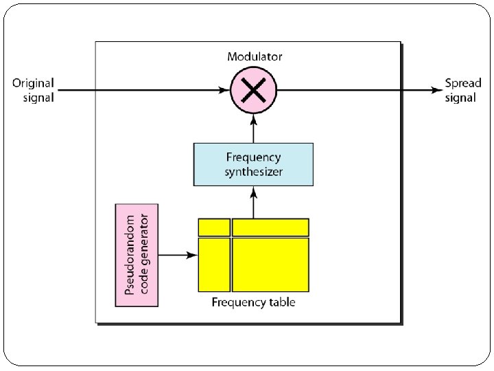
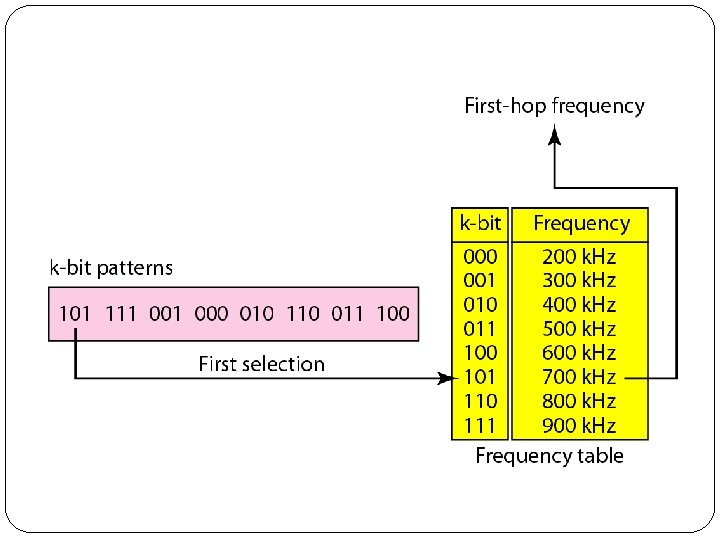
1. Frequency Hopping Spread Spectrum (FHSS) � The frequency hopping spread spectrum (FHSS) technique uses M different carrier frequencies that are modulated by the source signal. � At one moment, the signal modulates one carrier frequency; at the next moment, the signal modulates another carrier frequency. � Although the modulation is done using one carrier frequency at a time, M frequencies are used in the long run. � The bandwidth occupied by a source after spreading is Bp. HSS » B. � Figure shows the general layout for FHSS. � A pseudorandom code generator, called pseudorandom noise (PN), creates a k-bit pattern for every hopping period Th.
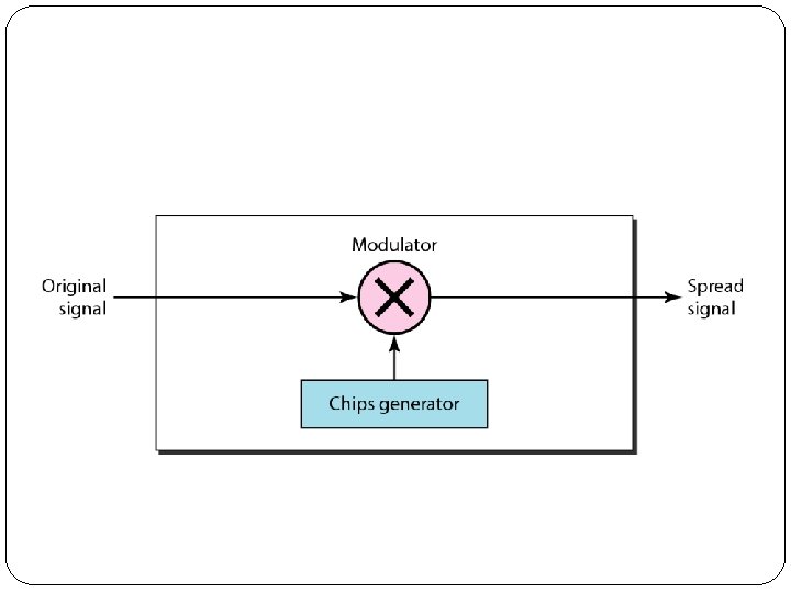
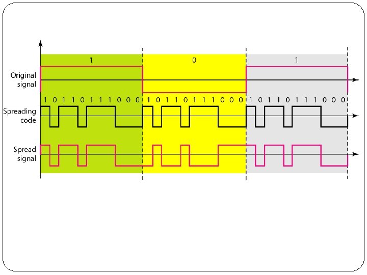
2. Direct Sequence Spread Spectrum (DSSS) �This technique also expands the bandwidth of the original signal, but the process is different. �In DSSS, we replace each data bit with 11 bits using a spreading code. �In other words, each bit is assigned a code of 11 bits, called chips, where the chip rate is 11 times that of the data bit. �Figure shows the concept of DSSS.
Multiple Access
Taxonomy of multiple-access protocols
Random Access �In random access or contention methods, no station is superior to another station and none is assigned the control over another. �No station permits, or does not permit, another station to send. �At each instance, a station that has data to send uses a procedure defined by the protocol to make a decision on whether or not to send.
ALOHA �The medium is shared between the stations. �When a station sends data, another station may attempt to do so at the same time. �The data from the two stations collide and become garbled. �Pure ALOHA �The original ALOHA protocol is called pure ALOHA. �This is a simple, but elegant protocol. �The idea is that each station sends a frame whenever it has a frame to send. �However, since there is only one channel to share, there is the possibility of collision between frames from different stations
Frames in a pure ALOHA network
�It is obvious that we need to resend the frames that have been destroyed during transmission. �The pure ALOHA protocol relies on acknowledgments from the receiver. �When a station sends a frame, it expects the receiver to send an acknowledgment. �If the acknowledgment does not arrive after a time -out period, the station assumes that the frame (or the acknowledgment) has been destroyed and resends the frame.
Procedure for pure ALOHA protocol
Vulnerable time for pure ALOHA protocol
Slotted ALOHA �A station may send soon after another station has started or soon before another station has finished. �Slotted ALOHA was invented to improve the efficiency of pure ALOHA. �In slotted ALOHA we divide the time into slots and force the station to send only at the beginning of the time slot. �Because a station is allowed to send only at the beginning of the synchronized time slot, if a station misses this moment, it must wait until the beginning of the next time slot.
Frames in a slotted ALOHA network
Vulnerable time for slotted ALOHA protocol
Carrier Sense Multiple Access (CSMA) � The chance of collision can be reduced if a station senses the � medium before trying to use it. �Non Persistent CSMA-Wait for some till it finds channel is free � 1 -Persistent CSMA-Continuously Monitors Two stations will collide if both are waiting �P-Persistent CSMA-depend upon probability of station want to transmits � Carrier sense multiple access (CSMA) requires that each station first listen to the medium (or check the state of the medium) before sending. � In other words, CSMA is based on the principle "sense before transmit" or "listen before talk. "
Space/time model of the collision in CSMA
Vulnerable time in CSMA Ø Vulnerable time for CSMA is the propagation time Tp. It is the time required for signal to go from one end of medium to the other. By the time 1 st reaches the farthest end , all the middle stations have heard the bit , so they will refrain from sending.
Carrier Sense Multiple Access with Collision Detection (CSMA/CD) �In this method, a station monitors the medium after it sends a frame to see if the transmission was successful. �If so, the station is finished. �If, however, there is a collision, the frame is sent again.
Collision of the first bit in CSMA/CD
Controlled Access �In controlled access, the stations consult one another to find which station has the right to send. �A station cannot send unless it has been authorized by other stations. �Three popular controlled-access methods: �Reservation �Polling �Token Passing
1. Reservation �In the reservation method, a station needs to make a reservation before sending data. �Time is divided into intervals. In each interval, a reservation frame precedes the data frames sent in that interval. �If there are N stations in the system, there are exactly N reservation minislots in the reservation frame. �Each minislot belongs to a station. �When a station needs to send a data frame, it makes a reservation in its own minislot. �The stations that have made reservations can send their data frames after the reservation frame.
Reservation access method
2. Polling �Polling works with topologies in which one device is designated as a primary station and the other devices are secondary stations. �All data exchanges must be made through the primary device even when the ultimate destination is a secondary device. �The primary device controls the link; the secondary devices follow its instructions. �It is up to the primary device to determine which device is allowed to use the channel at a given time. �The primary device, therefore, is always the initiator of a session.
Select and poll functions in polling access method
�If the primary wants to receive data, it asks the secondaries if they have anything to send; this is called poll function. �If the primary wants to send data, it tells the secondary to get ready to receive; this is called select function.
3. Token Passing � In the token-passing method, the stations in a network are organized in a logical ring. � In other words, for each station, there is a predecessor and a successor. � The predecessor is the station which is logically before the station in the ring; the successor is the station which is after the station in the ring. � The current station is the one that is accessing the channel now. � The right to this access has been passed from the predecessor to the current station. � The right will be passed to the successor when the current station has no more data to send.
�A special packet called a token circulates through the ring. �The possession of the token gives the station the right to access the channel and send its data. �When a station has some data to send, it waits until it receives the token from its predecessor. �It then holds the token and sends its data. �When the station has no more data to send, it releases the token, passing it to the next logical station in the ring. �The station cannot send data until it receives the token again in the next round. �In this process, when a station receives the token
�Token management is needed for this access method. �Stations must be limited in the time they can have possession of the token. �The token must be monitored to ensure it has not been lost or destroyed.
Logical ring and physical topology in token-passing access method
Channelization �Channelization is a multiple-access method in which the available bandwidth of a link is shared in time, frequency, or through code, between different stations. �Three channelization protocols: FDMA, TDMA, and CDMA
1. Frequency-Division Multiple Access (FDMA) �In frequency-division multiple access (FDMA), the available bandwidth is divided into frequency bands. �Each station is allocated a band to send its data. �In other words, each band is reserved for a specific station, and it belongs to the station all the time. �Each station also uses a bandpass filter to confine the transmitter frequencies. �To prevent station interferences, the allocated bands are separated from one another by small guard bands.
�FDMA specifies a predetermined frequency band for the entire period of communication. �This means that stream data (a continuous flow of data that may not be packetized) can easily be used with FDMA.
2. Time-Division Multiple Access (TDMA) �In time-division multiple access (TDMA), the stations share the bandwidth of the channel in time. �Each station is allocated a time slot during which it can send data. �Each station transmits data in is assigned time slot.
�The main problem with TDMA lies in achieving synchronization between the different stations. �Each station needs to know the beginning of its slot and the location of its slot. �This may be difficult because of propagation delays introduced in the system if the stations are spread over a large area. �To compensate for the delays, we can insert guard times. �Synchronization is normally accomplished by having some synchronization bits (normally referred to as preamble bits) at the beginning of
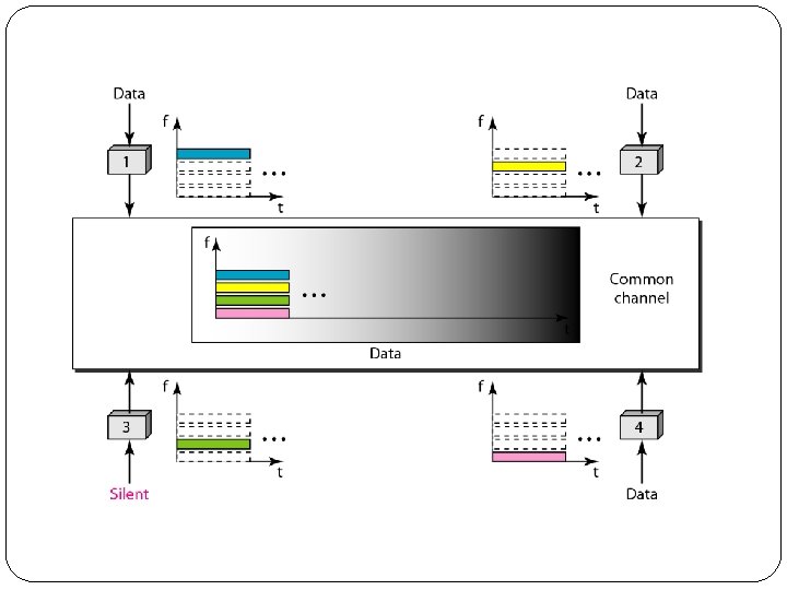
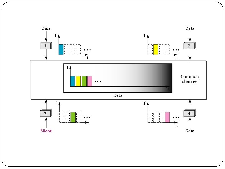
3. Code-Division Multiple Access (CDMA) �CDMA differs from FDMA because only one channel occupies the entire bandwidth of the link. �It differs from TDMA because all stations can send data simultaneously; there is no timesharing. �CDMA simply means communication with different codes. �The codes assigned to ‘n’ stations should have following properties �multiplication of a code with itself gives result ‘n’ �multiplication of a code with another gives result ‘ 0’
Simple idea of communication with code
�Let us assume we have four stations 1, 2, 3, and 4 connected to the same channel. �The data from station 1 are d 1 , from station 2 are d 2, and so on. �The code assigned to the first station is c 1, to the second is c 2, and so on.