
MultipleBanked Register File Architecture On the Value Locality


紹介する文献 • Multiple-Banked Register File Architecture • On the Value Locality of Store Instructions • Completion Time Multiple Branch Prediction for Enhancing Trace Cache Performance • Circuits for Wide-Window Superscalar Processor • Trace Preconstruction • A Hardware Mechanism for Dynamic Extraction and Relayout of Program Hot Spots • A Fully Associative Software-Managed Cache Design • Performance Analysis of the Alpha 21264 -based Compaq ES 40 System • Piranha: A Scalable Architecture Based on Single Chip Multiprocessing 3
Session 8 – Microarchitecture Innovations Multiple-Banked Register File Architecture Jose-Lorenzo Cruz et al. Universitat Politecnica de Catalunya, Spain ISCA-2000 p. 316 -325 4
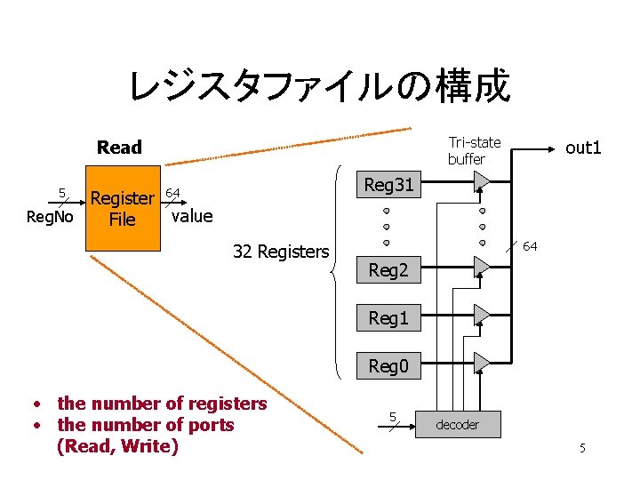
レジスタファイルの構成 Tri-state buffer Read 5 out 1 Reg 31 64 Register Reg. No value File 32 Registers 64 Reg 2 Reg 1 Reg 0 • the number of registers • the number of ports (Read, Write) 5 decoder 5
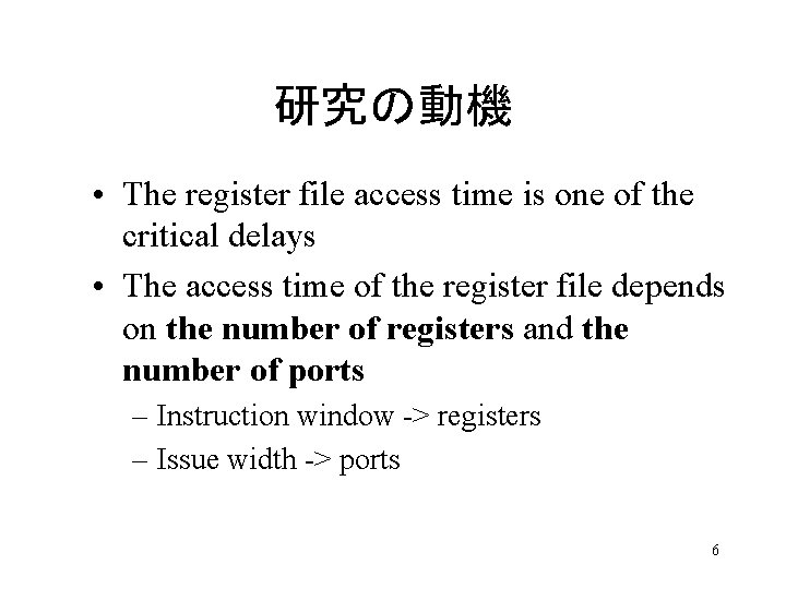
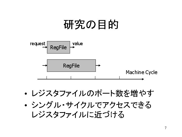
研究の動機 • The register file access time is one of the critical delays • The access time of the register file depends on the number of registers and the number of ports – Instruction window -> registers – Issue width -> ports 6
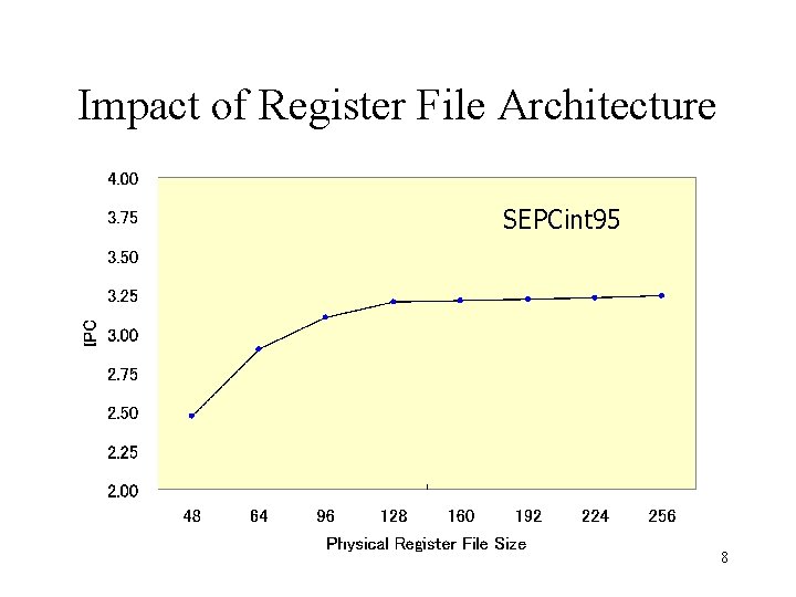
Impact of Register File Architecture SEPCint 95 8
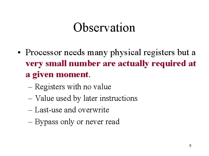
Observation • Processor needs many physical registers but a very small number are actually required at a given moment. – Registers with no value – Value used by later instructions – Last-use and overwrite – Bypass only or never read 9
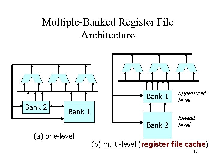
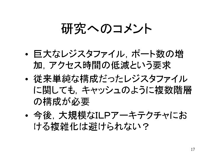
Multiple-Banked Register File Architecture Bank 2 Bank 1 uppermost level Bank 2 lowest level Bank 1 (a) one-level (b) multi-level (register file cache) 10
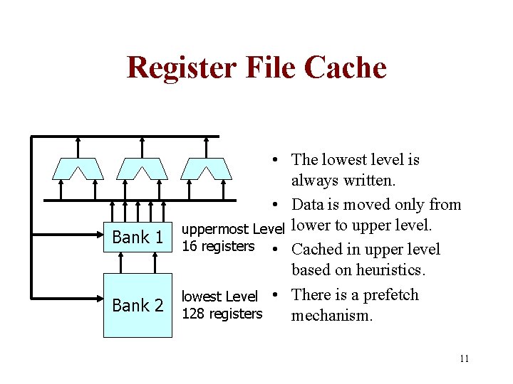
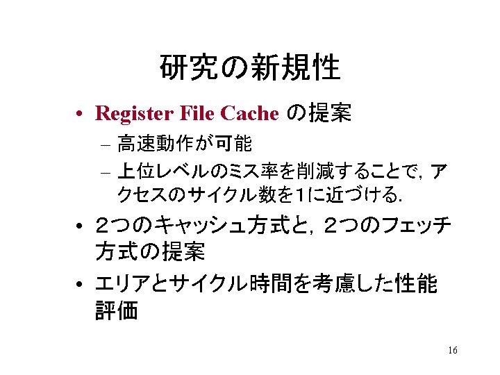
Register File Cache Bank 1 Bank 2 • The lowest level is always written. • Data is moved only from uppermost Level lower to upper level. 16 registers • Cached in upper level based on heuristics. lowest Level • There is a prefetch 128 registers mechanism. 11
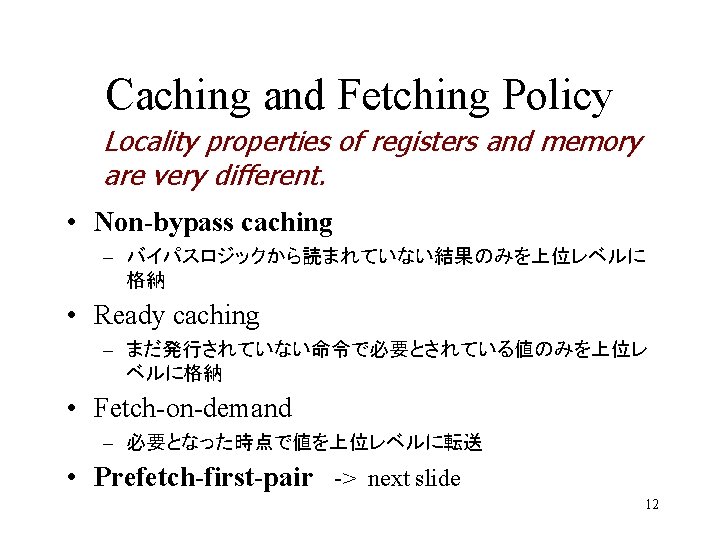
Caching and Fetching Policy Locality properties of registers and memory are very different. • Non-bypass caching – バイパスロジックから読まれていない結果のみを上位レベルに 格納 • Ready caching – まだ発行されていない命令で必要とされている値のみを上位レ ベルに格納 • Fetch-on-demand – 必要となった時点で値を上位レベルに転送 • Prefetch-first-pair -> next slide 12
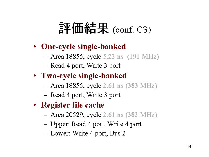
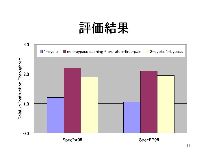
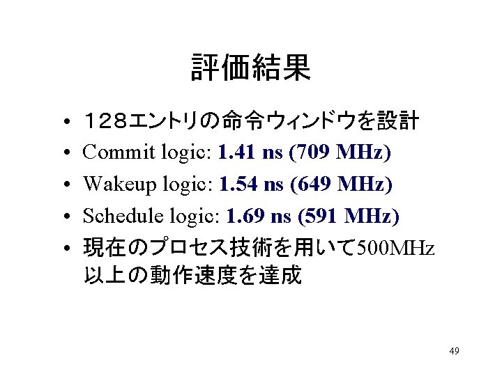
評価結果 (conf. C 3) • One-cycle single-banked – Area 18855, cycle 5. 22 ns (191 MHz) – Read 4 port, Write 3 port • Two-cycle single-banked – Area 18855, cycle 2. 61 ns (383 MHz) – Read 4 port, Write 3 port • Register file cache – Area 20529, cycle 2. 61 ns (382 MHz) – Upper: Read 4 port, Write 4 port – Lower: Write 4 port, Bus 2 14

Session 5 a – Analysis of Workloads and Systems On the Value Locality of Store Instructions Kevin M. Lepak et al. University of Wisconsin ISCA-2000 p. 182 -191 18
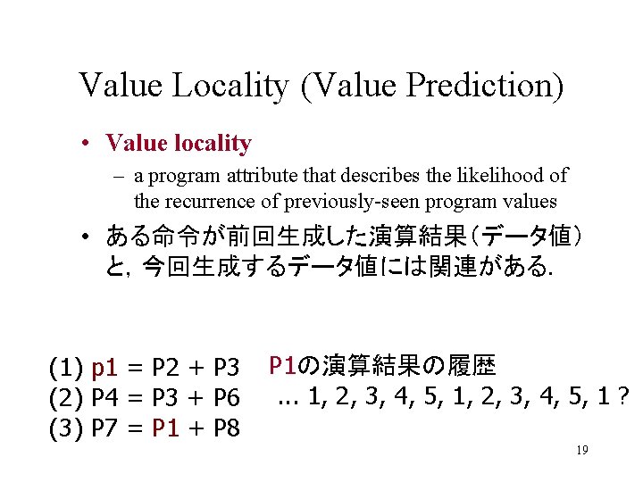
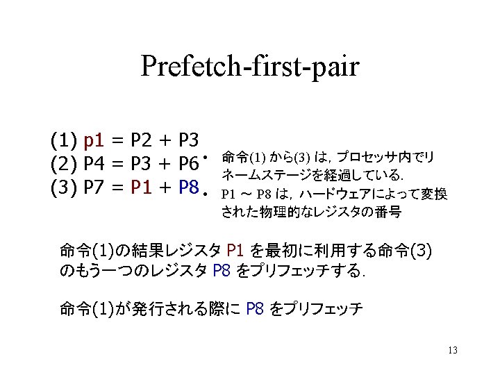
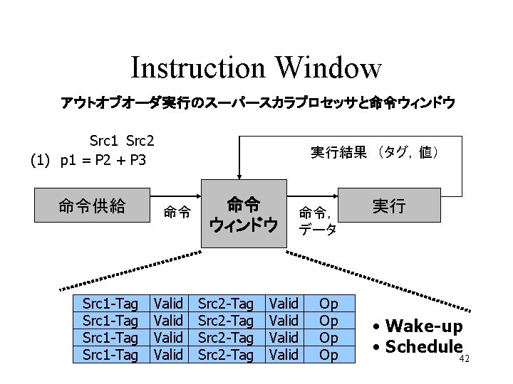
Value Locality (Value Prediction) • Value locality – a program attribute that describes the likelihood of the recurrence of previously-seen program values • ある命令が前回生成した演算結果(データ値) と,今回生成するデータ値には関連がある. (1) p 1 = P 2 + P 3 (2) P 4 = P 3 + P 6 (3) P 7 = P 1 + P 8 P 1の演算結果の履歴. . . 1, 2, 3, 4, 5, 1 ? 19
研究の目的 • Much publication has focused on load instruction outcome. • Examine the implications of store value locality – Introduce the notion of silent stores – Introduce two new definitions of multiprocessor true sharing – Reduce multiprocessor data and address traffic 20
Memory-centric and producer-centric Locality • Program structure store value locality – The locality of values written by a particular static store. • Message-passing store value locality – The locality of values written to a particular address in data memory. 21
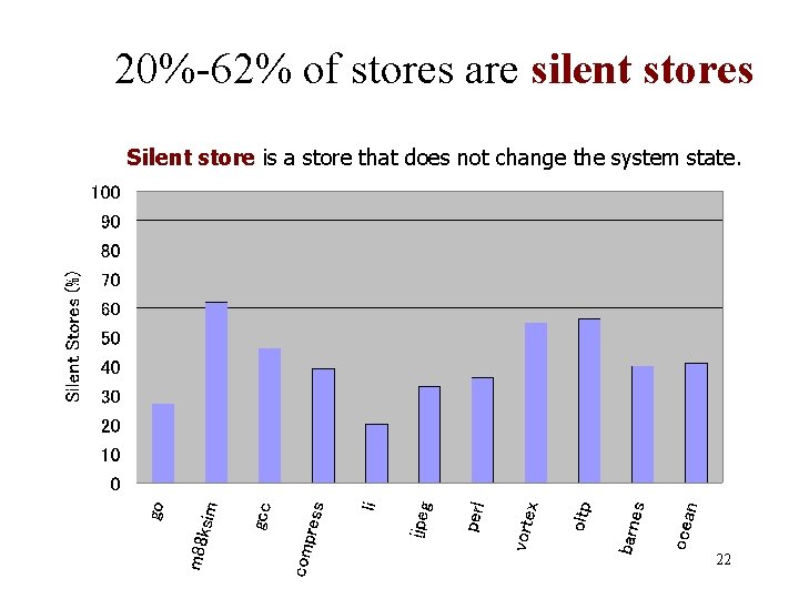
20%-62% of stores are silent stores Silent store is a store that does not change the system state. 22
Silent Store Removal Mechanism • Realistic Method – All previous store addresses must be known. – Load the data from the memory subsystem. – If the data values are equal, the store is update -silent. • Remove from the LSQ and flag the RUU entry – If store is silent, the store retires with no memory access. 23
Evaluation Results • Writeback Reduction – Range in reduction from 81% to 0% – Average 33% reduction • Instruction Throughput – Speedups of 6. 3% and 6. 9% for realistic and perfect removal mechanisms. 24
New Definition of False Sharing • Multiprocessor applications – All of the previous definitions rely on the specific addresses in the same block. – No attempt is made to determine when the invalidation of a block is unnecessary because the value stored in the line does not change. – Silent stores and stochastically silent stores 25
Address-based Definition of Sharing • Cold Miss [Dubois 1993] – The first miss to a given block by a processor • Essential Miss – A cold miss is an essential miss – If during the lifetime of a block, the processor accesses a value defined by another processor since the last essential miss to that block, it is an essential miss. • Pure True Sharing miss (PTS) – An essential miss that is not cold. • Pure False Sharing miss (PFS) – A non-essential miss. 26
Update-based False Sharing (UFS) • Essential Miss – A cold miss is an essential miss – If during the lifetime of a block, the processor accesses an address which has had a different data value defined by another processor since the last essential miss to that block, it is an essential miss. 27

Stochastic False Sharing (SFS) • It seems intuitive that – if we define false sharing to compensate for the effect of silent stores that we could also define it in the presence of stochastically silent stores (values that are trivially predictable via some mechanism) 28
研究の新規性 • Overall characterization of store value locality • Notion of silent stores • Uniprocessor speedup by squashing silent stores • Definition of UFS and SFS • How to exploit UFS to reduce address and data bus traffic on shared memory multiprocessors 29
Session 2 a – Exploiting Traces Completion Time Multiple Branch Prediction for Enhancing Trace Cache Performance Ryan Rakvic et al. Carnegie Mellon University ISCA-2000 p. 47 -58 31
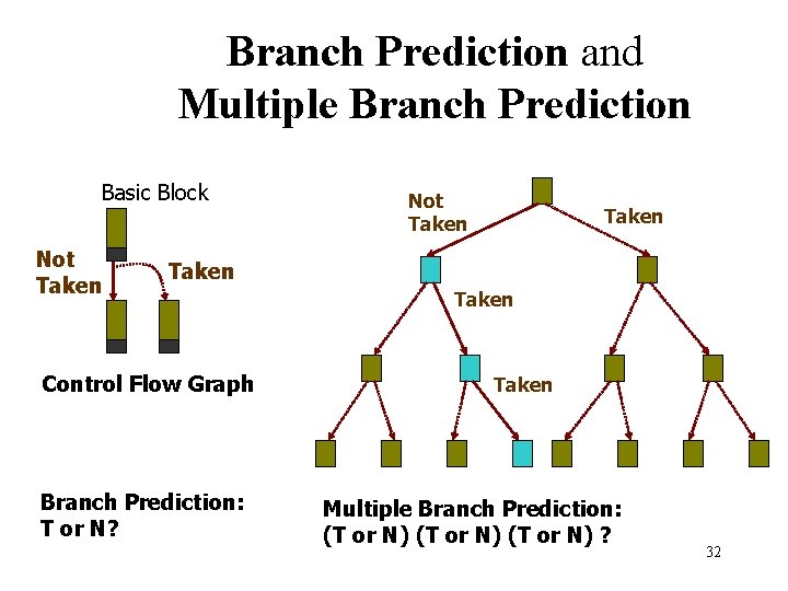
Branch Prediction and Multiple Branch Prediction Basic Block Not Taken Control Flow Graph Branch Prediction: T or N? Taken Multiple Branch Prediction: (T or N) ? 32
動機と目的 • Wide Instruction Fetching – 4 -way -> 8 -way • Multiple branch prediction – Branch Execution Rate: about 15% – One branch prediction per cycle is not enough. • Tree-Based Multiple Branch Predictor (TMP) 33
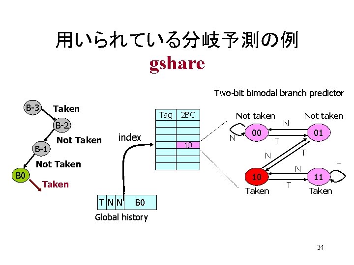
用いられている分岐予測の例 gshare Two-bit bimodal branch predictor B-3 Taken Tag 2 BC Not taken B-2 B-1 Not Taken index 10 N 01 T T N Not Taken B 0 Not taken 10 Taken TNN N T T 11 Taken B 0 Global history 34
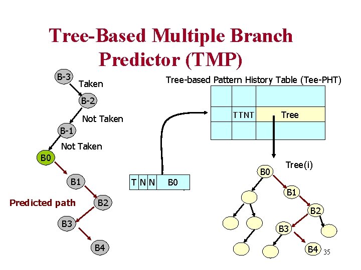
Tree-Based Multiple Branch Predictor (TMP) B-3 Taken Tree-based Pattern History Table (Tee-PHT) B-2 Tree TTNT Not Taken B-1 Not Taken B 0 B 1 Predicted path TGlobal N N history B 0 B 2 B 3 B 0 Tree(i) B 1 B 2 B 3 B 4 35
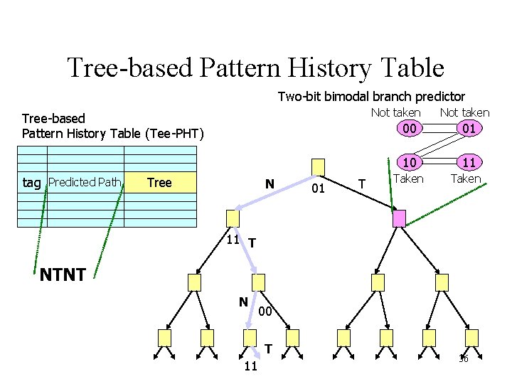
Tree-based Pattern History Table Two-bit bimodal branch predictor Not taken Tree-based Pattern History Table (Tee-PHT) tag Predicted Path Tree N 01 T Not taken 00 01 10 11 Taken 11 T NTNT N 00 T 11 36
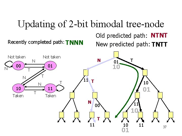
Updating of 2 -bit bimodal tree-node Old predicted path: NTNT New predicted path: TNTT Recently completed path: TNNN Not taken N 00 Not taken N 01 T Taken N T T 01 10 T N 10 N T 11 T 10 01 11 Taken N 11 00 10 T 11 10 01 11 37
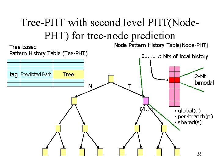
Tree-PHT with second level PHT(Node. PHT) for tree-node prediction Node Pattern History Table(Node-PHT) Tree-based Pattern History Table (Tee-PHT) tag Predicted Path 01. . . 1 n bits of local history Tree N 2 -bit bimodal T 01. . . 1 • global(g) • per-branch(p) • shared(s) 38
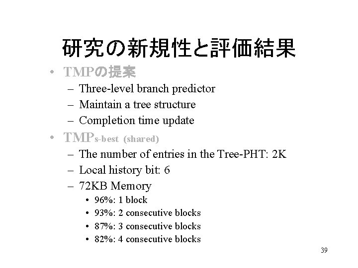
研究の新規性と評価結果 • TMPの提案 – Three-level branch predictor – Maintain a tree structure – Completion time update • TMPs-best (shared) – The number of entries in the Tree-PHT: 2 K – Local history bit: 6 – 72 KB Memory • • 96%: 1 block 93%: 2 consecutive blocks 87%: 3 consecutive blocks 82%: 4 consecutive blocks 39
Session 6 – Circuit Considerations Circuits for Wide-Window Superscalar Processor Dana S. Henry, Bradley C. Kuszmaul, Gabriel H. Loh and Rahul Sami ISCA-2000 p. 236 -247 41
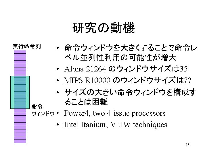
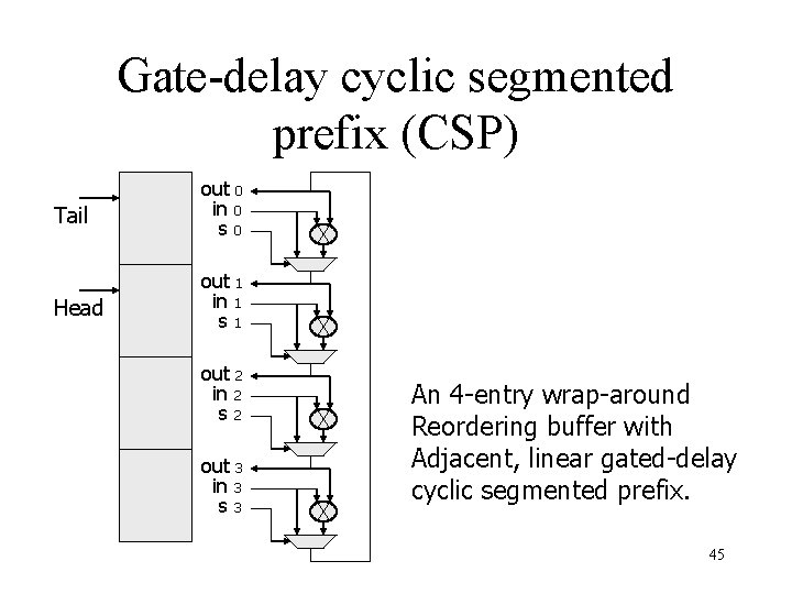
Gate-delay cyclic segmented prefix (CSP) Tail out 0 in 0 s 0 Head out 1 in 1 s 1 out 2 in 2 s 2 out 3 in 3 s 3 An 4 -entry wrap-around Reordering buffer with Adjacent, linear gated-delay cyclic segmented prefix. 45
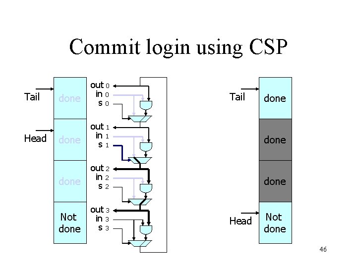
Commit login using CSP Tail Head done out 0 in 0 s 0 done out 1 in 1 s 1 done out 2 in 2 s 2 done Not done out 3 in 3 s 3 Tail Head done Not done 46
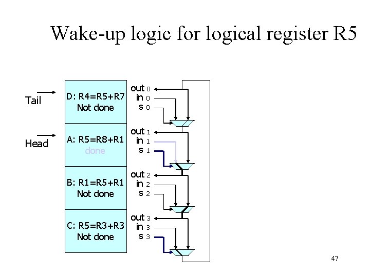
Wake-up logic for logical register R 5 Tail out 0 D: R 4=R 5+R 7 in 0 s 0 Not done Head out 1 A: R 5=R 8+R 1 in 1 s 1 done out 2 B: R 1=R 5+R 1 in 2 s 2 Not done out 3 C: R 5=R 3+R 3 in 3 s 3 Not done 47
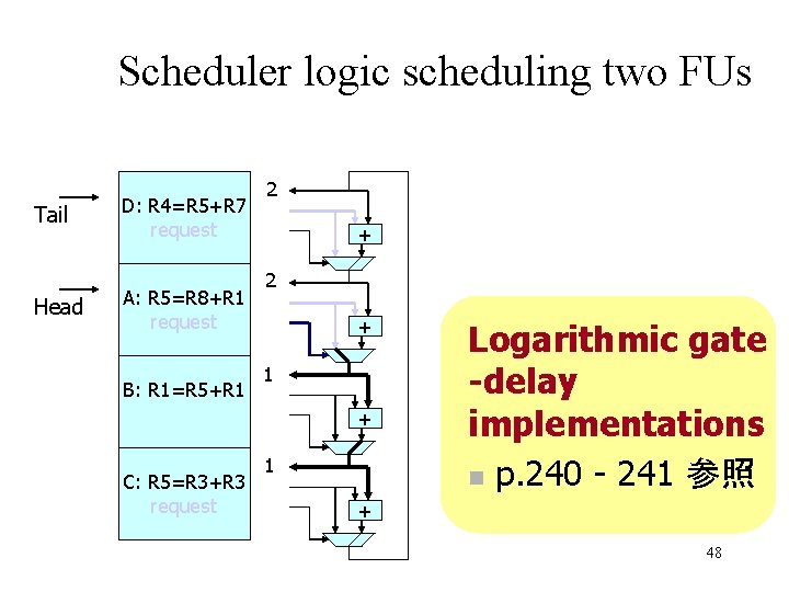
Scheduler logic scheduling two FUs Tail Head D: R 4=R 5+R 7 request A: R 5=R 8+R 1 request B: R 1=R 5+R 1 2 + 1 + C: R 5=R 3+R 3 request 1 Logarithmic gate -delay implementations n p. 240 - 241 参照 + 48

Session 2 a – Exploiting Traces Trace Preconstruction Quinn Jacobson et al. Sun Microsystems ISCA-2000 p. 37 -46 51
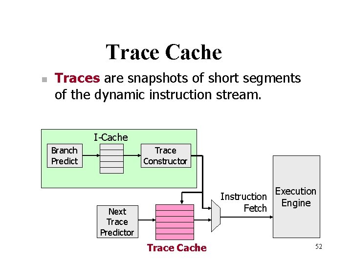
Trace Cache n Traces are snapshots of short segments of the dynamic instruction stream. I-Cache Branch Predict Trace Constructor Instruction Fetch Next Trace Predictor Trace Cache Execution Engine 52
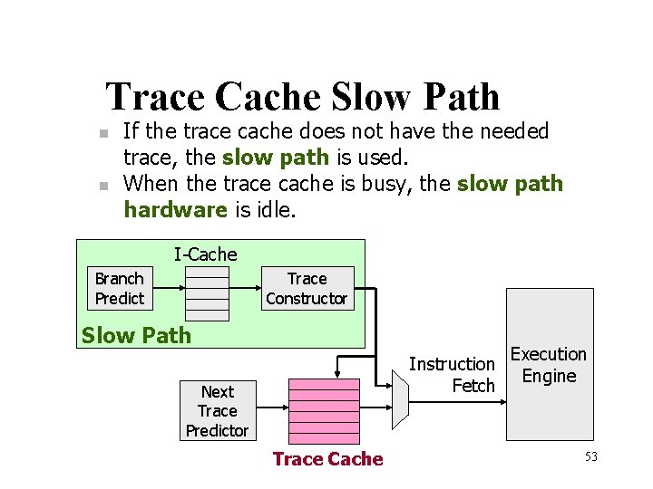
Trace Cache Slow Path n n If the trace cache does not have the needed trace, the slow path is used. When the trace cache is busy, the slow path hardware is idle. I-Cache Branch Predict Trace Constructor Slow Path Instruction Fetch Next Trace Predictor Trace Cache Execution Engine 53
目的 • Trace cache enables high bandwidth, low latency instruction supply. • Trace cache performance may suffer due to capacity and compulsory misses. • By performing a function analogous to prefetching, trace preconstruction augments a trace cache. 54
Preconstruction Method n For preconstruction to be successful n n Region start points must identify instructions that the actual execution path will reach in the future. Heuristic n n loop back edge procedure call 55
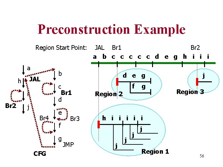
Preconstruction Example Region Start Point: a JAL h i Br 2 j Br 4 b d e g c Br 1 d e f g CFG JAL Br 1 Br 2 a b c c c d e g h i i i Br 3 JMP f g Region 2 j Region 3 h i i i j j Region 1 56
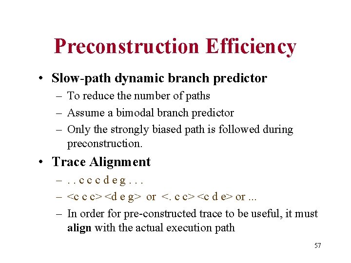
Preconstruction Efficiency • Slow-path dynamic branch predictor – To reduce the number of paths – Assume a bimodal branch predictor – Only the strongly biased path is followed during preconstruction. • Trace Alignment –. . cccdeg. . . – <c c c> <d e g> or <. c c> <c d e> or. . . – In order for pre-constructed trace to be useful, it must align with the actual execution path 57
Conclusions • One implementation of trace preconstruction – SPECint 95 benchmarks with large working set sizes – Reduce the trace cache miss rates from 30% to 80% – 3% to 10% overall performance improvement 58
Session 2 a – Exploiting Traces A Hardware Mechanism for Dynamic Extraction and Relayout of Program Hot Spots Matthew C. Merten et al. Coordinated Science Lab ISCA-2000 p. 59 -70 59
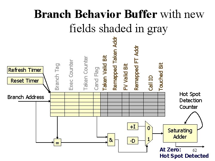
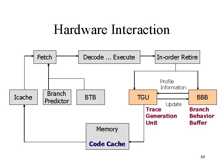
目的 • Dynamic extraction and relayout of program hot spots – A hardware-driven profiling scheme for identifying program hot spots to support runtime optimization, ISCA 1999 • Improve instruction fetch rate 61
Branch Address = & +I 0 -D 1 Touched Bit Call ID Remapped FT Addr FV Valid Bit Remapped Taken Addr Taken Valid Bit Cand Flag Taken Counter Reset Timer Exec Counter Refresh Timer Branch Tag Branch Behavior Buffer with new fields shaded in gray Hot Spot Detection Counter Saturating Adder At Zero: 62 Hot Spot Detected
Memory-Based Code Cache • Use a region of memory called a code cache to contain the translated code. • Standard paging mechanisms are used to manage a set of virtual pages reserved for the code cache. • The code cache pages can be allocated by the operating system and marked as read-only executable code. • The remapping hardware must be allowed to write this region. 63
Hardware Interaction Fetch Icache Branch Predictor Decode. . . Execute In-order Retire Profile Information BTB TGU BBB Update Memory Trace Generation Unit Branch Behavior Buffer Code Cache 64
Code Deployment • Original code cannot be altered • Transfer to the optimized code is handled by the Branch Target Buffer. – BTB target for the entry point branch is updated with the address of the entry point target in the code cache. • Optimized code consists of only the original code. 65
Trace Generation Algorithm • Scan Mode – Search for a trace entry point. This is the initial mode following hot spot detection • Fill Mode – Construct a trace by writing each retired instructions into the memory-based code cache. • Pending Mode – Pause trace construction until a new path is executed. 66
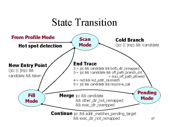
State Transition From Profile Mode Hot spot detection New Entry Point (jcc || jmp) && candidate && taken Fill Mode Scan Mode Cold Branch (jcc || jmp) && !candidate End Trace 2 -> jcc && candidate && both_dir_remapped 3 -> jcc && !candidate && off_path_branch_cnt > max_off_path_allowed 4 -> red && red_addr_mismatch 5 -> jcc && candidate && recursive_call Merge jcc && candidate && other_dir_not_remapped && exec_dir_reampped Pending Mode Continue jcc && addr_matches_pending_target && exec_dir_not_remapped 67
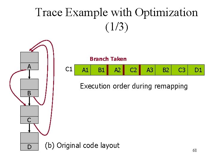
Trace Example with Optimization (1/3) Branch Taken A B C 1 A 1 B 1 A 2 C 2 A 3 B 2 C 3 D 1 Execution order during remapping C D (b) Original code layout 68
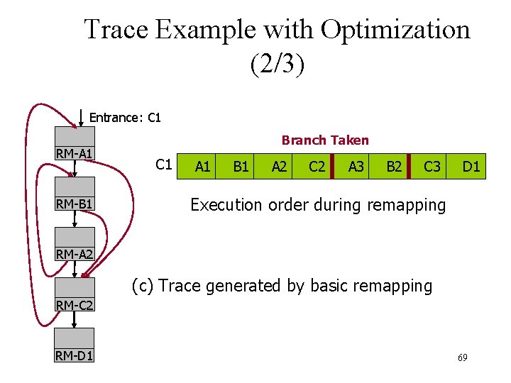
Trace Example with Optimization (2/3) Entrance: C 1 RM-A 1 RM-B 1 Branch Taken C 1 A 1 B 1 A 2 C 2 A 3 B 2 C 3 D 1 Execution order during remapping RM-A 2 (c) Trace generated by basic remapping RM-C 2 RM-D 1 69
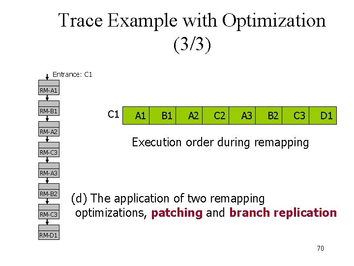
Trace Example with Optimization (3/3) Entrance: C 1 RM-A 1 RM-B 1 RM-A 2 RM-C 3 C 1 A 1 B 1 A 2 C 2 A 3 B 2 C 3 D 1 Execution order during remapping RM-A 3 RM-B 2 RM-C 3 (d) The application of two remapping optimizations, patching and branch replication RM-D 1 70
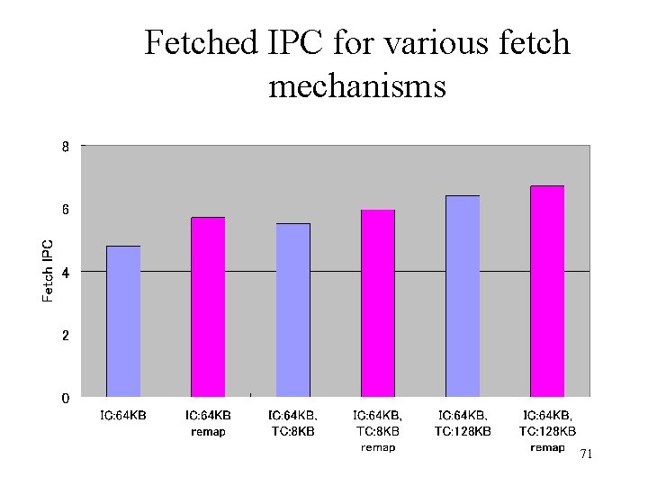
Fetched IPC for various fetch mechanisms 71
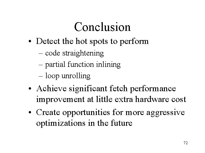
Conclusion • Detect the hot spots to perform – code straightening – partial function inlining – loop unrolling • Achieve significant fetch performance improvement at little extra hardware cost • Create opportunities for more aggressive optimizations in the future 72

Session 3 – Memory Hierarchy Improvement A Fully Associative Software. Managed Cache Design Erik G. Hallnor et al. The University of Michigan ISCA-2000 p. 107 -116 74
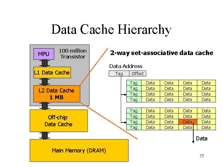
Data Cache Hierarchy MPU 100 million Transistor L 1 Data Cache L 2 Data Cache 1 MB Off-chip Data Cache 2 -way set-associative data cache Data Address Tag Offset Tag Tag Data Data Data Data Data Data Data Data Data Main Memory (DRAM) 75
研究の目的 • Processor-memory gap – miss latencies approaching a thousand instruction execution time • On-chip SRAM caches in excess of one megabyte [Alpha 21364] • Re-examination of how secondary caches are organized and managed – Practical, fully associative, software managed secondary cache system 76
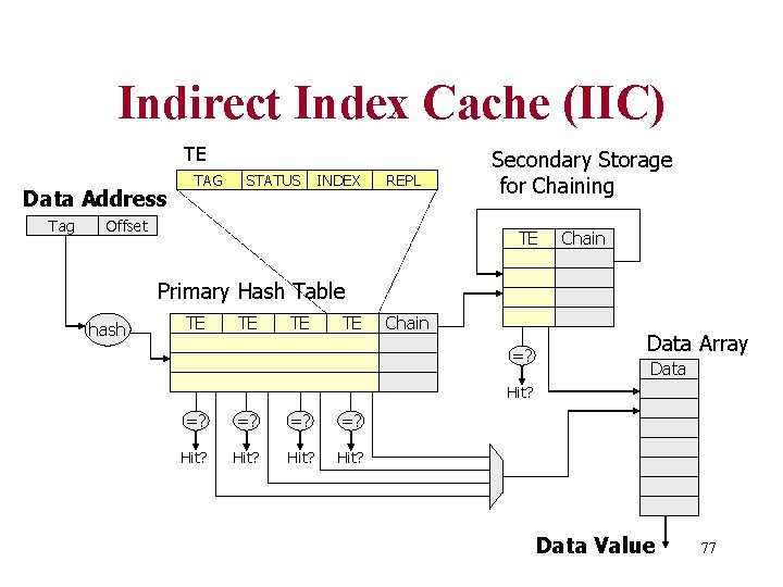
Indirect Index Cache (IIC) TE Data Address Tag TAG STATUS INDEX REPL Offset Secondary Storage for Chaining TE Chain Primary Hash Table hash TE TE Chain =? Data Array Data Hit? =? =? Hit? Data Value 77
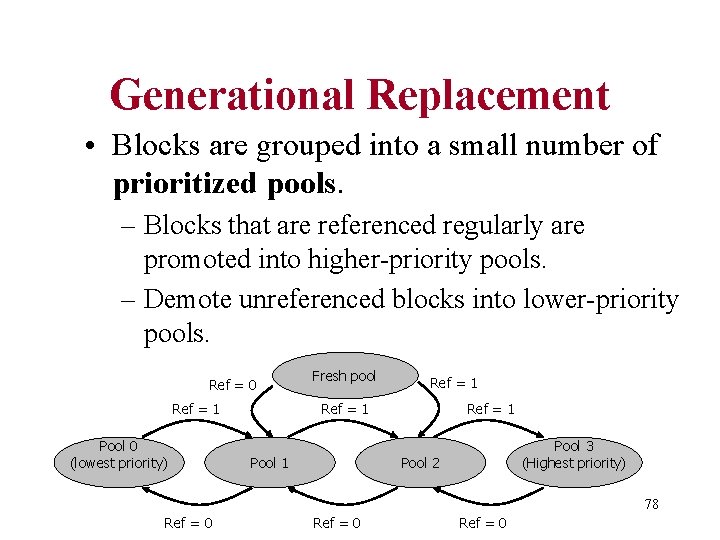
Generational Replacement • Blocks are grouped into a small number of prioritized pools. – Blocks that are referenced regularly are promoted into higher-priority pools. – Demote unreferenced blocks into lower-priority pools. Ref = 0 Ref = 1 Pool 0 (lowest priority) Fresh pool Ref = 1 Pool 1 Ref = 1 Pool 3 (Highest priority) Pool 2 78 Ref = 0
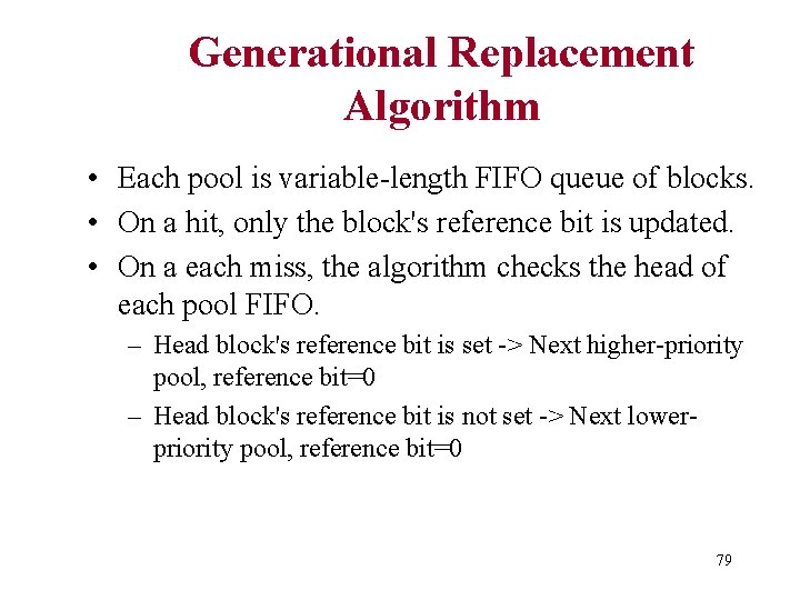
Generational Replacement Algorithm • Each pool is variable-length FIFO queue of blocks. • On a hit, only the block's reference bit is updated. • On a each miss, the algorithm checks the head of each pool FIFO. – Head block's reference bit is set -> Next higher-priority pool, reference bit=0 – Head block's reference bit is not set -> Next lowerpriority pool, reference bit=0 79
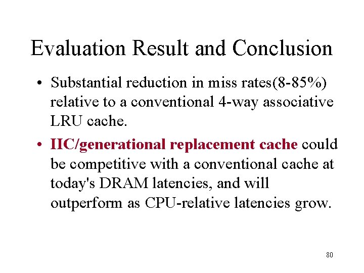
Evaluation Result and Conclusion • Substantial reduction in miss rates(8 -85%) relative to a conventional 4 -way associative LRU cache. • IIC/generational replacement cache could be competitive with a conventional cache at today's DRAM latencies, and will outperform as CPU-relative latencies grow. 80
Session 5 a – Analysis of Workloads and Systems Performance Analysis of the Alpha 21264 -based Compaq ES 40 System Zarka Cvetanovic, R. E. Kessler Compaq Computer Corporation ISCA-2000 p. 192 -202 82
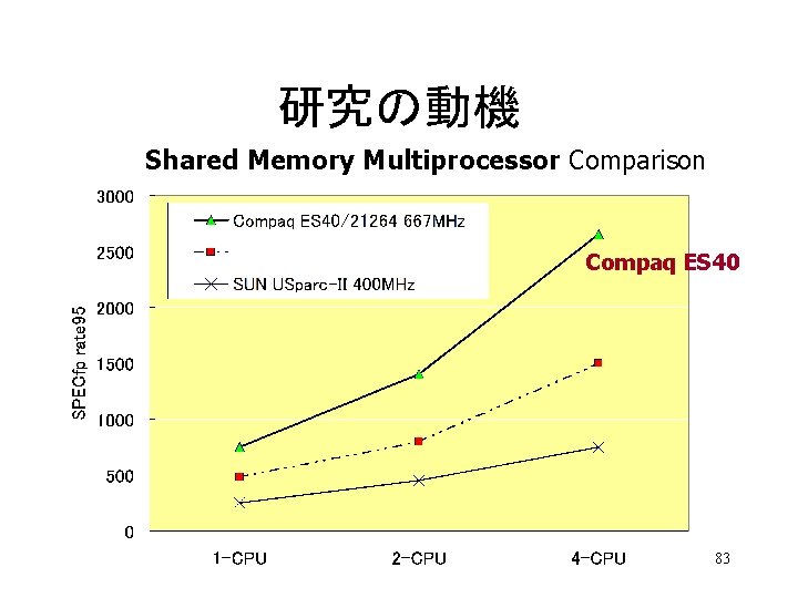
研究の動機 Shared Memory Multiprocessor Comparison Compaq ES 40 83
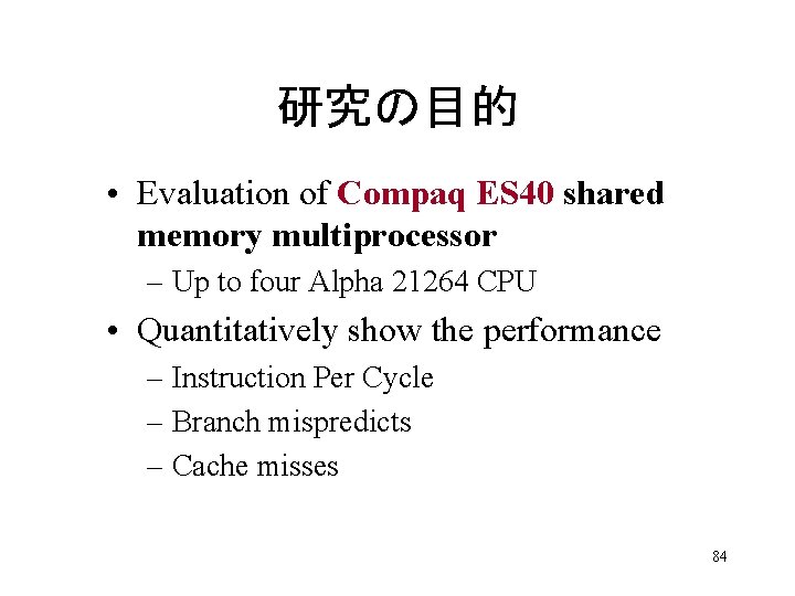
研究の目的 • Evaluation of Compaq ES 40 shared memory multiprocessor – Up to four Alpha 21264 CPU • Quantitatively show the performance – Instruction Per Cycle – Branch mispredicts – Cache misses 84
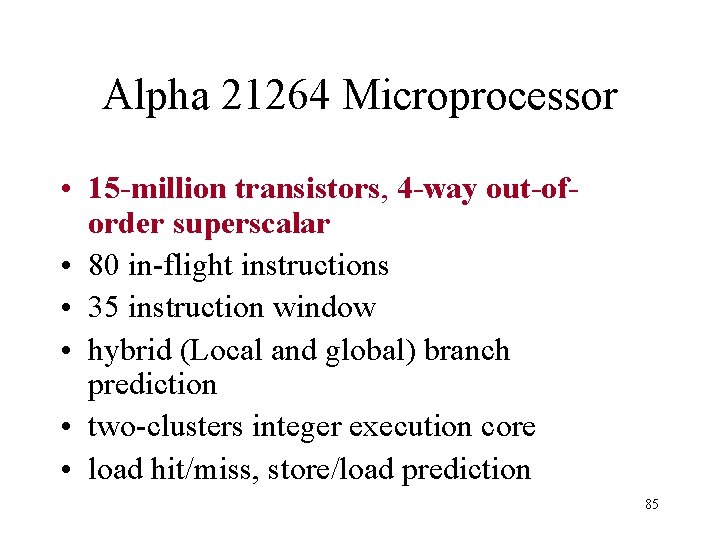
Alpha 21264 Microprocessor • 15 -million transistors, 4 -way out-oforder superscalar • 80 in-flight instructions • 35 instruction window • hybrid (Local and global) branch prediction • two-clusters integer execution core • load hit/miss, store/load prediction 85
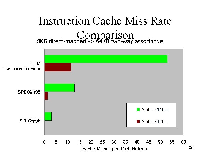
Instruction Cache Miss Rate Comparison 8 KB direct-mapped -> 64 KB two-way associative Transactions Per Minute 86
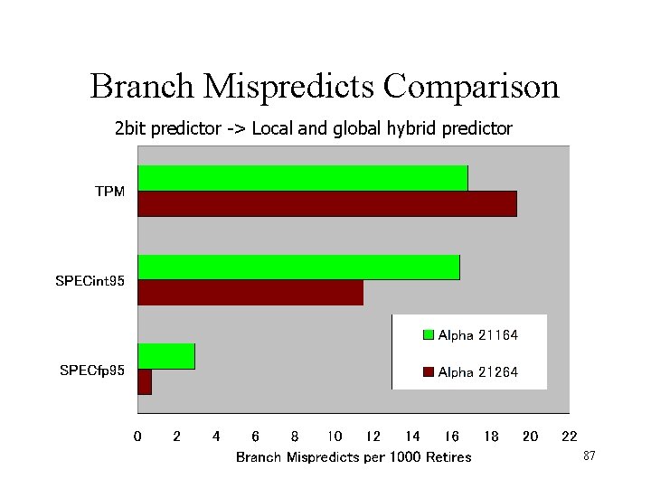
Branch Mispredicts Comparison 2 bit predictor -> Local and global hybrid predictor 87
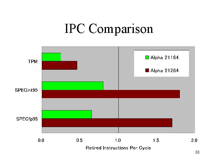
IPC Comparison 88
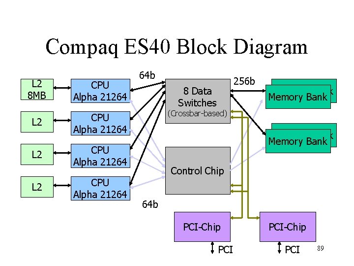
Compaq ES 40 Block Diagram L 2 8 MB CPU Alpha 21264 L 2 L 2 64 b 8 Data Switches Memory Bank (Crossbar-based) Memory Bank CPU Alpha 21264 256 b Control Chip 64 b PCI-Chip PCI 89
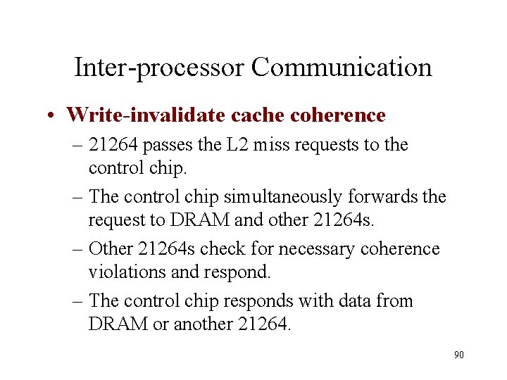
Inter-processor Communication • Write-invalidate cache coherence – 21264 passes the L 2 miss requests to the control chip. – The control chip simultaneously forwards the request to DRAM and other 21264 s. – Other 21264 s check for necessary coherence violations and respond. – The control chip responds with data from DRAM or another 21264. 90
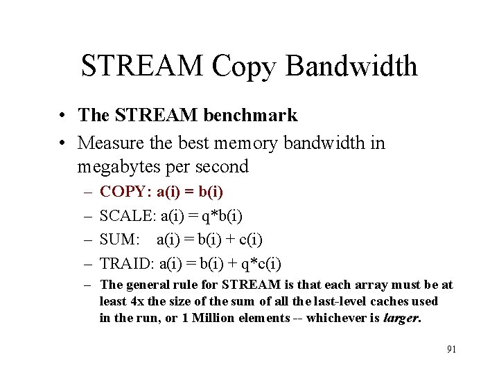
STREAM Copy Bandwidth • The STREAM benchmark • Measure the best memory bandwidth in megabytes per second – – COPY: a(i) = b(i) SCALE: a(i) = q*b(i) SUM: a(i) = b(i) + c(i) TRAID: a(i) = b(i) + q*c(i) – The general rule for STREAM is that each array must be at least 4 x the size of the sum of all the last-level caches used in the run, or 1 Million elements -- whichever is larger. 91
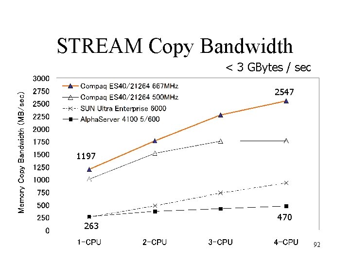
STREAM Copy Bandwidth < 3 GBytes / sec 2547 1197 263 470 92
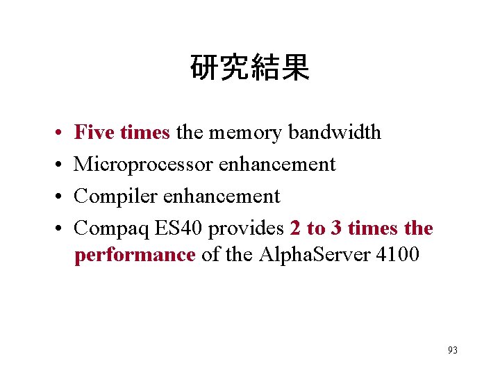
研究結果 • • Five times the memory bandwidth Microprocessor enhancement Compiler enhancement Compaq ES 40 provides 2 to 3 times the performance of the Alpha. Server 4100 93
Session 7 – Extracting Parallelism Piranha: A Scalable Architecture Based on Single Chip Multiprocessing Luiz Andre Barroso Compaq Computer Corporation ISCA-2000 p. 282 -293 95
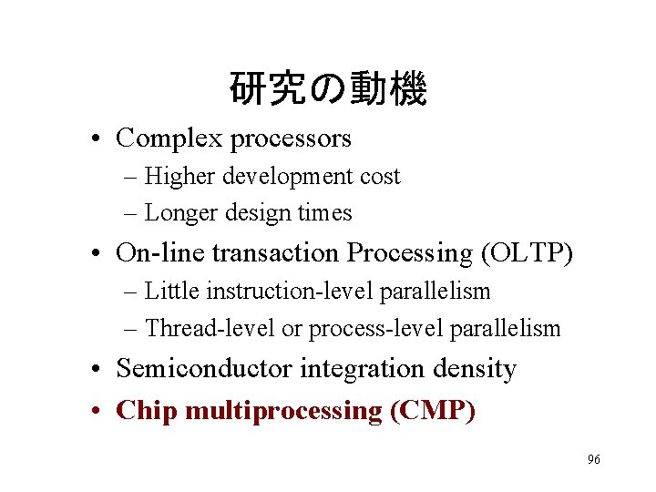
研究の動機 • Complex processors – Higher development cost – Longer design times • On-line transaction Processing (OLTP) – Little instruction-level parallelism – Thread-level or process-level parallelism • Semiconductor integration density • Chip multiprocessing (CMP) 96

研究の目的 • Piranha: a research prototype at Compaq – Targeted at parallel commercial workloads – Chip multiprocessing architectures – Small team, modest investment, short design time • General-purpose microprocessors or Piranha? 97
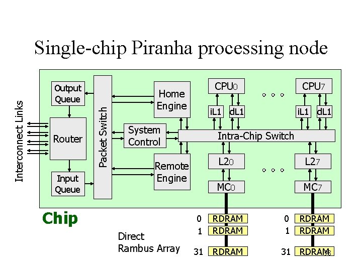
Output Queue Router Input Queue Packet Switch Interconnect Links Single-chip Piranha processing node Home Engine System Control Direct Rambus Array CPU 7 i. L 1 d. L 1 Intra-Chip Switch Remote Engine Chip CPU 0 L 27 MC 0 MC 7 0 1 RDRAM 31 RDRAM 98
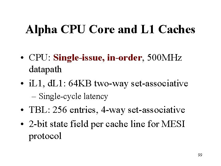
Alpha CPU Core and L 1 Caches • CPU: Single-issue, in-order, 500 MHz datapath • i. L 1, d. L 1: 64 KB two-way set-associative – Single-cycle latency • TBL: 256 entries, 4 -way set-associative • 2 -bit state field per cache line for MESI protocol 99
Intra-Chip Switch (ICS) • • ICS manages 27 clients. Conceptually, ICS is a crossbar. Eight internal datapaths Capacity of 32 GB/sec – 500 MHz, 64 bit bus (8 Byte), 8 datapaths – 500 MHz x 8 Byte x 8 = 32 GB/sec – 3 times the available memory bandwidth 100
Second-Level Cache • L 2: 1 MB unified instruction/data cache – Physically partitioned into eight banks • Each bank is 8 -way set-associative • Non-inclusive on-chip cache hierarchy – Keep a duplicate copy of the L 1 tags and state • L 2 controllers are responsible for coherence within a chip. 101
Memory Controller • Eight memory controllers • Each RDRAM channel has a maximum 1. 6 GB/sec • Maximum local memory bandwidth of 12. 8 GB/sec 102
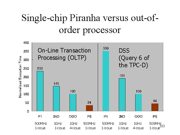
Single-chip Piranha versus out-oforder processor On-Line Transaction Processing (OLTP) 500 MHz 1 -issue 1 GHz 500 MHz 4 -issue 1 -issue DSS (Query 6 of the TPC-D) 500 MHz 1 GHz 1 -issue 1 GHz 4 -issue 500 MHz 103 1 -issue
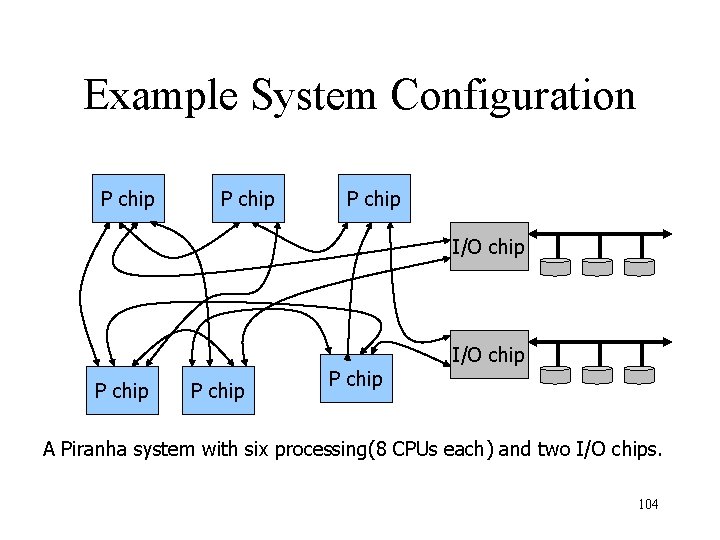
Example System Configuration P chip P chip I/O chip A Piranha system with six processing(8 CPUs each) and two I/O chips. 104
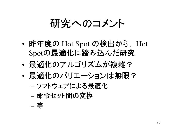
研究の新規性 • Detailed evaluation of database workloads in the context of CMP • Simple processor, standard ASIC design – short time, small team size, small investment 105
- Slides: 106